Structural testing of tidal turbine blades is vital due to several reasons. Firstly, it allows for the optimization of blade performance, ensuring efficient energy conversion and maximizing power output. Secondly, it ensures the reliability and safety of the blades, enabling them to withstand harsh marine conditions and reducing the risk of failure or damage. Thirdly, structural testing helps assess the durability of the blades, determining their fatigue life and enabling effective maintenance strategies. Additionally, it aids in designing cost-effective solutions by evaluating materials, manufacturing techniques, and configurations. Finally, structural testing facilitates regulatory compliance, ensuring that blades meet the necessary standards and certifications for deployment in tidal energy projects. Overall, structural testing plays a crucial role in enhancing performance, safety, durability, cost-effectiveness, and regulatory compliance of tidal turbine blades.
- structural testing
- tidal energy
- structural integrity
- full-scale testing
1. Introduction
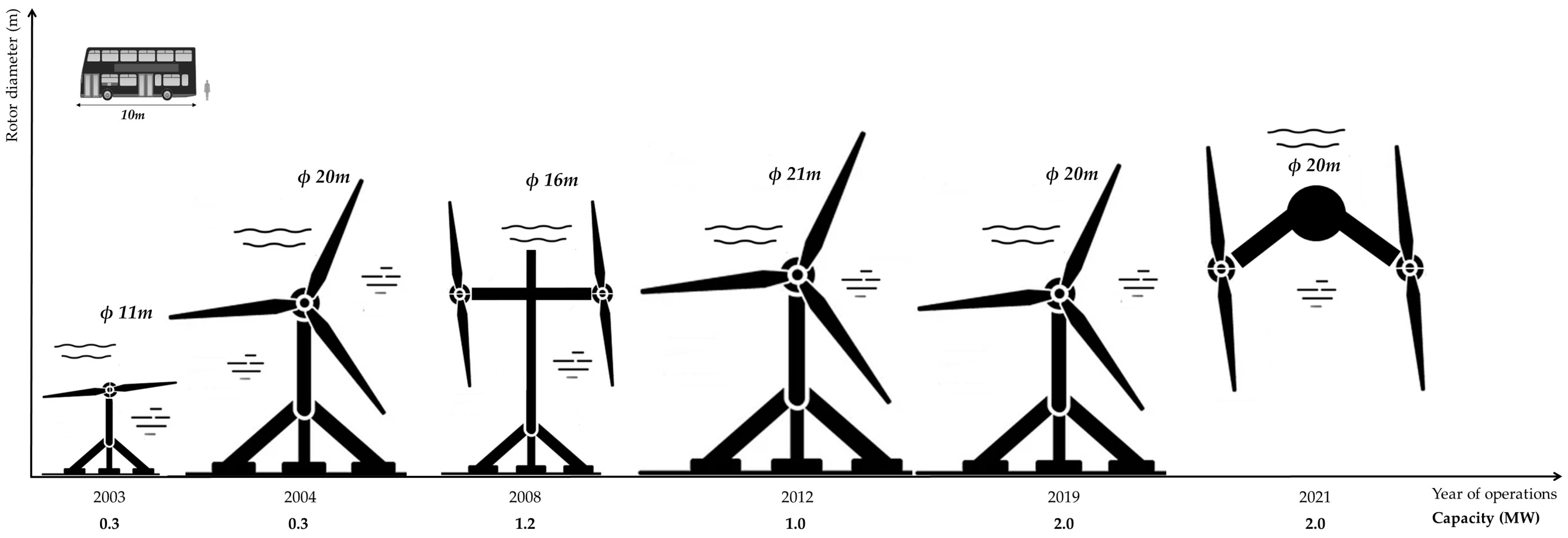
2. Structural Testing Procedure
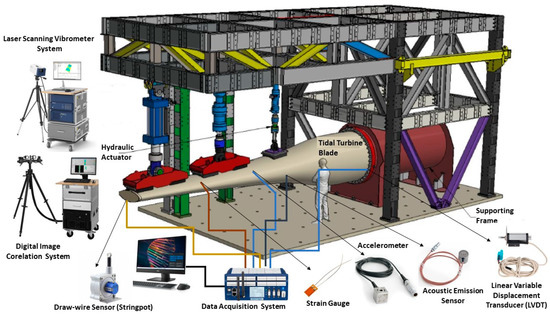
2.1. Blade Set-Up and Installation
| Equipment/Transducer | Working Principles |
|---|---|
| LSV System | This noncontact velocity transducer system works based on the Doppler effect. The system measures the frequency shift of the laser-scattered beam from the vibrating surface relating to the reference beam [20]. |
| DIC System | The system compares the digital images of a part or a test piece at different stages of deformation and compares these images to produce strain and deflection measurements. Measurements are limited to the area seen by the DIC cameras [21]. |
| Accelerometer | The piezoelectric materials in accelerometers generate electrical charge due to the change of motion or vibration. Then, they measure the variation of the electric charge generated as it is proportional to the acceleration of the object [22]. |
| Strain Gauge | The resistance of the strain gauge varies depending on the applied force to it, as a result of movement of the surface it is adhered to. Therefore, the change in electrical resistance is measured to identify the strain of the testing object [23]. |
| Draw-Wire Sensor | It uses a highly flexible steel wire to measure the linear movements of the objects. |
| LVDT | It measures displacement based on the mutual induction of primary and secondary windings. The movement of the core creates a different electromagnetic field (EMF) in both windings, and the difference is used to measure displacement [24]. |
| 3D Laser Scanner | It can be used to obtain a point cloud survey that captures the as-built geometry of the tidal blade, test fixtures and fittings, as well as full 3D geometry of the deformed blade under loading conditions. |
| Acoustic Emission Sensor | It converts high-frequency stress waves into voltage. Then, the voltages are amplified to process the acoustic emission signal data to identify defects [25]. |
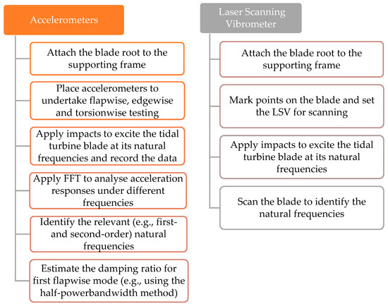
2.2. Dynamic Testing
2.2. Dynamic Testing
2.3. Static Testing
-
Flapwise direction from pressure side to suction side;
-
Flapwise direction from suction side to pressure side;
-
Edgewise direction from trailing edge towards leading edge;
-
Edgewise direction from leading edge towards trailing edge;
-
Torsion-only stiffness distribution (this can be neglected if the torsional extreme loadings are not critical for the blade design.) [19].
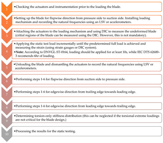
Figure 4. Static testing procedure for tidal turbine blades [18,19].
2.4. Fatigue Testing
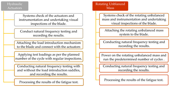
2.5. Residual Strength Testing
- Lemonis, G. Wave and Tidal Energy Conversion. Encyclopedia of Energy 2004, 7, 385–396, doi:10.1016/B0-12-176480-X/00344-2.
- Ocean Energy Europe Ocean Energy Key Trends and Statistics 2021; 2022;
- Renewable Energy from Tidal Currents; Graz, Austria, 2012;
- Zhou, Z.; Scuiller, F.; Charpentier, J.-F.; Benbouzid, M.; Tang, T.; An, T.T. An Up-to-Date Review of Large Marine Tidal Current Turbine Technologies; 2014;
- Rajak, D.K.; Pagar, D.D.; Kumar, R.; Pruncu, C.I. Recent Progress of Reinforcement Materials: A Comprehensive Overview of Composite Materials. Journal of Materials Research and Technology 2019, 8, 6354–6374, doi:10.1016/J.JMRT.2019.09.068.
- Hasan, M.; Zhao, J.; Jiang, Z. Micromanufacturing of Composite Materials: A Review. International Journal of Extreme Manufacturing 2019, 1, 012004, doi:10.1088/2631-7990/AB0F74.
- Hsissou, R.; Seghiri, R.; Benzekri, Z.; Hilali, M.; Rafik, M.; Elharfi, A. Polymer Composite Materials: A Comprehensive Review. Compos Struct 2021, 262, 113640, doi:10.1016/J.COMPSTRUCT.2021.113640.
- Magagna, Davide.; Uihlein, Andreas.; Monfardini, Riccardo.; European Commission. Joint Research Centre. JRC Ocean Energy Status Report Technology, Market and Economic Aspects of Ocean Energy in Europe : 2016 Edition.; Publications Office, 2016;
- Walker, S.; Thies, P.R. A Review of Component and System Reliability in Tidal Turbine Deployments. Renewable and Sustainable Energy Reviews 2021, 151, doi:10.1016/J.RSER.2021.111495.
- Yu, G. qing; Ren, Y. ru; Zhang, T. tian; Xiao, W. shen; Jiang, H. yong Hashin Failure Theory Based Damage Assessment Methodology of Composite Tidal Turbine Blades and Implications for the Blade Design. China Ocean Engineering 2018 32:2 2018, 32, 216–225, doi:10.1007/S13344-018-0023-Z.
- Chen, L.; Lam, W.H. A Review of Survivability and Remedial Actions of Tidal Current Turbines. Renewable and Sustainable Energy Reviews 2014, 43, 891–900, doi:10.1016/j.rser.2014.11.071.
- Failed Tidal Turbine Explained at Symposium Available online: https://www.cbc.ca/news/canada/nova-scotia/failed-tidal-turbine-explained-at-symposium-1.1075510 (accessed on 24 March 2023).
- Murray, R. Passively Adaptive Tidal Turbine Blades: Design Methodology and Experimental Testing; 2016;
- FastBlade - World’s First Regenerative Fatigue Test Facility Available online: https://www.fastblade.eng.ed.ac.uk/ (accessed on 7 March 2023).
- Test and Demonstration Facilities for Wind Energy Needed to Promote a Competitive Wind Industry in Denmark; Langebrogade, Denmark, 2016;
- Finnegan, W.; Jiang, Y.; Meier, P.; Hung, L.C.; Fagan, E.; Wallace, F.; Glennon, C.; Flanagan, M.; Flanagan, T.; Goggins, J. Numerical Modelling, Manufacture and Structural Testing of a Full-Scale 1 MW Tidal Turbine Blade. Ocean Engineering 2022, 112717, doi:10.1016/J.OCEANENG.2022.112717.
- Davies, P.; Dumergue, N.; Arhant, M.; Nicolas, E.; Paboeuf, S.; Mayorga, P. Material and Structural Testing to Improve Composite Tidal Turbine Blade Reliability. International Marine Energy Journal 2022, 5, 57–65, doi:10.36688/imej.5.57-65.
- IEC DTS 62600–3; Geneva 20, Switzerland, 2019;
- DNV GL DNVGL-ST-0164; 2015;
- Zipser, L.; Franke, H. Laser-Scanning Vibrometry for Ultrasonic Transducer Development. Sens Actuators A Phys 2004, 110, 264–268, doi:10.1016/J.SNA.2003.10.051.
- McCormick, N.; Lord, J. Digital Image Correlation for Structural Measurements. Proceedings of the Institution of Civil Engineers - Civil Engineering 2012, 165, 185–190, doi:10.1680/cien.11.00040.
- Niu, W.; Fang, L.; Xu, L.; Li, X.; Huo, R.; Guo, D.; Qi, Z.; Niu, W.; Fang, L.; Xu, L.; et al. Summary of Research Status and Application of MEMS Accelerometers. Journal of Computer and Communications 2018, 6, 215–221, doi:10.4236/JCC.2018.612021.
- Tutak, P. Application of Strain Gauges in Measurements of Strain Distribution in Complex Objects. JACSM 2014, 6, 135–135, doi:10.1515/jacsm-2015-0004.
- Qian, Z.; Fan, Y.; Lu, Z. Application of Draw-Wire Displacement Sensors on Structural Health Monitoring of Jiangyin Bridge.; The International Society for Optical Engineering : San Diego, CA, United States, March 16 2006; Vol. 6176.
- He, Y.; Li, M.; Meng, Z.; Chen, S.; Huang, S.; Hu, Y.; Zou, X. An Overview of Acoustic Emission Inspection and Monitoring Technology in the Key Components of Renewable Energy Systems. Mech Syst Signal Process 2021, 148, 107146, doi:10.1016/J.YMSSP.2020.107146.
References
- Lemonis, G. Wave and Tidal Energy Conversion. Encycl. Energy 2004, 7, 385–396.
- Ocean Energy Europe. Ocean Energy Europe Ocean Energy Key Trends and Statistics 2021; Ocean Energy Europe: Belgium, Brussels, 2022.
- Renewable Energy from Tidal Currents; ANDRITZ HYDRO Hammerfest: Graz, Austria, 2012; pp. 6–10.
- Zhou, Z.; Scuiller, F.; Charpentier, J.-F.; Benbouzid, M.; Tang, T.; An, T.T. An Up-to-Date Review of Large Marine Tidal Current Turbine Technologies; IEEE: Piscataway, NJ, USA, 2014.
- Rajak, D.K.; Pagar, D.D.; Kumar, R.; Pruncu, C.I. Recent Progress of Reinforcement Materials: A Comprehensive Overview of Composite Materials. J. Mater. Res. Technol. 2019, 8, 6354–6374.
- Hasan, M.; Zhao, J.; Jiang, Z. Micromanufacturing of Composite Materials: A Review. Int. J. Extrem. Manuf. 2019, 1, 012004.
- Hsissou, R.; Seghiri, R.; Benzekri, Z.; Hilali, M.; Rafik, M.; Elharfi, A. Polymer Composite Materials: A Comprehensive Review. Compos. Struct. 2021, 262, 113640.
- Davide, M.; Andreas, U.; Riccardo, M.; Joint Research Centre (European Commission). JRC Ocean Energy Status Report Technology, Market and Economic Aspects of Ocean Energy in Europe: 2016 Edition; Publications Office: Luxembourg, 2016.
- Walker, S.; Thies, P.R. A Review of Component and System Reliability in Tidal Turbine Deployments. Renew. Sustain. Energy Rev. 2021, 151, 111495.
- Yu, G.Q.; Ren, Y.R.; Zhang, T.T.; Xiao, W.S.; Jiang, H.Y. Hashin Failure Theory Based Damage Assessment Methodology of Composite Tidal Turbine Blades and Implications for the Blade Design. China Ocean. Eng. 2018, 32, 216–225.
- Chen, L.; Lam, W.H. A Review of Survivability and Remedial Actions of Tidal Current Turbines. Renew. Sustain. Energy Rev. 2014, 43, 891–900.
- Failed Tidal Turbine Explained at Symposium. Available online: https://www.cbc.ca/news/canada/nova-scotia/failed-tidal-turbine-explained-at-symposium-1.1075510 (accessed on 24 March 2023).
- Murray, R. Passively Adaptive Tidal Turbine Blades: Design Methodology and Experimental Testing; Elsevier: Amsterdam, The Netherlands, 2016.
- Finnegan, W.; Jiang, Y.; Meier, P.; Hung, L.C.; Fagan, E.; Wallace, F.; Glennon, C.; Flanagan, M.; Flanagan, T.; Goggins, J. Numerical Modelling, Manufacture and Structural Testing of a Full-Scale 1 MW Tidal Turbine Blade. Ocean Eng. 2022, 266, 112717.
- FastBlade-World’s First Regenerative Fatigue Test Facility. Available online: https://www.fastblade.eng.ed.ac.uk/ (accessed on 7 March 2023).
- Test and Demonstration Facilities for Wind Energy Needed to Promote a Competitive Wind Industry in Denmark; MEGAVIND: Langebrogade, Denmark, 2016.
- Davies, P.; Dumergue, N.; Arhant, M.; Nicolas, E.; Paboeuf, S.; Mayorga, P. Material and Structural Testing to Improve Composite Tidal Turbine Blade Reliability. Int. Mar. Energy J. 2022, 5, 57–65.
- IEC DTS 62600–3; Marine Energy-Wave, Tidal and Other Water Current Converters-Part 3: Measurement of Mechanical Loads. International Electrotechnical Commission: Geneva, Switzerland, 2019.
- DNVGL-ST-0164; Tidal Turbines. Det Norske Veritas Germanischer Lloyd: Oslo, Norway, 2015.
- Zipser, L.; Franke, H. Laser-Scanning Vibrometry for Ultrasonic Transducer Development. Sens. Actuators A Phys. 2004, 110, 264–268.
- McCormick, N.; Lord, J. Digital Image Correlation for Structural Measurements. Proc. Inst. Civ. Eng.-Civ. Eng. 2012, 165, 185–190.
- Niu, W.; Fang, L.; Xu, L.; Li, X.; Huo, R.; Guo, D.; Qi, Z.; Niu, W.; Fang, L.; Xu, L.; et al. Summary of Research Status and Application of MEMS Accelerometers. J. Comput. Commun. 2018, 6, 215–221.
- Tutak, P. Application of Strain Gauges in Measurements of Strain Distribution in Complex Objects. JACSM 2014, 6, 135.
- Qian, Z.; Fan, Y.; Lu, Z. Application of Draw-Wire Displacement Sensors on Structural Health Monitoring of Jiangyin Bridge. In Proceedings of the Nondestructive Evaluation and Health Monitoring of Aerospace Materials, Composites, and Civil Infrastructure V, San Diego, CA, USA, 20 March 2006; Volume 6176.
- He, Y.; Li, M.; Meng, Z.; Chen, S.; Huang, S.; Hu, Y.; Zou, X. An Overview of Acoustic Emission Inspection and Monitoring Technology in the Key Components of Renewable Energy Systems. Mech. Syst. Signal Process. 2021, 148, 107146.
- Jiang, Y.; Finnegan, W.; Vanhari, A.K.; Meier, P.; Fagan, E.; Goggins, J. Natural Frequency Measurement of a 13-M Wind Turbine Blade Using Different Techniques. In Proceedings of the Civil Engineering Research in Ireland, Cork, Ireland, 27–28 August 2020; pp. 265–270.
