Submitted Successfully!
To reward your contribution, here is a gift for you: A free trial for our video production service.
Thank you for your contribution! You can also upload a video entry or images related to this topic.
Version Summary Created by Modification Content Size Created at Operation
1 -- 3045 2023-04-21 12:43:42 |
2 format Meta information modification 3045 2023-04-23 03:58:18 |

Video Upload Options

Do you have a full video?

Confirm

Are you sure to Delete?
Cite
If you have any further questions, please contact Encyclopedia Editorial Office.
Krismanto, A.U.; Mithulananthan, N.; Shah, R.; Setiadi, H.; Islam, M.R. Small-Signal Stability in Microgrid. Encyclopedia. Available online: https://encyclopedia.pub/entry/43321 (accessed on 29 March 2024).
Krismanto AU, Mithulananthan N, Shah R, Setiadi H, Islam MR. Small-Signal Stability in Microgrid. Encyclopedia. Available at: https://encyclopedia.pub/entry/43321. Accessed March 29, 2024.
Krismanto, Awan Uji, Nadarajah Mithulananthan, Rakibuzzaman Shah, Herlambang Setiadi, Md. Rabiul Islam. "Small-Signal Stability in Microgrid" Encyclopedia, https://encyclopedia.pub/entry/43321 (accessed March 29, 2024).
Krismanto, A.U., Mithulananthan, N., Shah, R., Setiadi, H., & Islam, M.R. (2023, April 21). Small-Signal Stability in Microgrid. In Encyclopedia. https://encyclopedia.pub/entry/43321
Krismanto, Awan Uji, et al. "Small-Signal Stability in Microgrid." Encyclopedia. Web. 21 April, 2023.
Small-Signal Stability in Microgrid
Edit

The microgrid (MG) system is a controlled and supervised power system consisting of renewable energy (RE)-based distributed generation (DG) units, loads, and energy storage. The MG can be operated autonomously or while connected to the grid. Higher intermittencies and uncertainties can be observed in MGs compared to the conventional power system, which is the possible source of small-signal stability in MG systems. It can be seen as disturbances around the stable operating point, which potentially lead to the small-signal instability problem within MGs. Small-signal instability issues also emerge due to the lack of damping torque in the MG. The integration of power electronic devices and complex control algorithms within MGs introduces novel challenges in terms of small-signal stability and possible resonances. The occurrence of interaction in a low- or no-inertia system might worsen the stability margin, leading to undamped oscillatory instability. The interaction within the MG is characterized by various frequency ranges, from low-frequency subsynchronous oscillation to high-frequency ranges around the harmonic frequencies.

interaction microgrid resonance

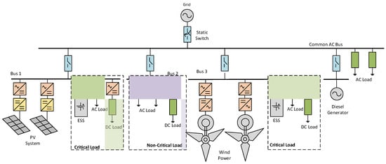
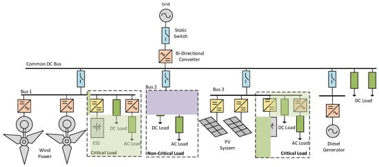
1. Microgrid Architectures

The type of microgrid (MG) system can be classified into feeder and facility MGs. A feeder-based MG mainly operates in synchronized operation with the distribution feeder or surrounding utilities to provide additional power injections, reactive power support, and ancillary service for enhancing the reliability of the electricity service. In contrast, a facility-based MG is proposed to ensure energy resilience for communities, specifically for critical loads or customers. Such an MG system can be operated both in grid-tied and autonomous modes during contingency periods due to extreme weather events.
The selection of MG architectures is a key issue. The architecture of the MG needs to be selected carefully to obtain the most benefits from the MG. The typical configuration of the MG system can mainly be classified into three groups according to the appearance of AC and DC buses. It can be categorized into the AC-microgrid (AC-MG), DC-microgrid (DC-MG), and AC-DC-microgrid (AC-DC-MG). In AC-MG, the operational voltage and current are in the AC form. Therefore, interfacing devices must be used to connect RE-based DG units to the AC bus. Hence, most of the RE-based DG units deploy DC/AC power electronic converters.
Figure 1 shows an example of the AC-MG system. The AC-MG usually consists of three buses where critical loads are integrated at buses 1 and 3, while noncritical loads are connected to bus 2. RE-based DG units (PV and wind) and energy storage systems (ESSs) are interfaced to the associated bus by a DC/AC converter to form the AC-MG. To ensure the power balance and overcome the shortfall in energy from RE-based DG units, a diesel generator, preferably a biodiesel generator (BDG), could be integrated. In the grid-tied operation, the AC power may flow directly from/to the MG system without an additional conversion process. Direct coupling between the main grid and the AC-MG ensures a synchronized operation of each DG unit within the MG and the main grid. Therefore, it is easier to maintain the local voltage and frequency as the main grid. On the other hand, in a DC-MG, an additional conversion process through the bidirectional DC/AC converter is required to facilitate grid-tied operation. Voltage and frequency deviations potentially emerge if the bidirectional converter fails to maintain the synchronized operation with the main grid. When those deviations cannot be restored, the MG system has to be disconnected from the grid to maintain the stability of the primary grid. Consequently, the electricity service is perturbed, and hence the system’s reliability could deteriorate. Furthermore, load, DG units, and ESS must follow the grid conditions [1]. The AC-MG system is feasible for both RE and non-RE-based DG units. It can be used in many applications, such as remote areas and commercial buildings, and as a backup for existing power systems [2].
Figure 1. AC microgrid architecture.
Figure 2 represents a typical structure of the DC-MG. Integration of the DC-MG into the main grid is provided by means of a bidirectional DC/AC converter system to facilitate power exchange between MG and the main grid. The RE-based DG units, ESS, and variable DC and AC loads are connected to DC buses through an AC/DC rectifier and DC/DC converter system. Two critical load buses with RE-based generators are presented in Figure 2. All the load-generation buses are connected to the point of common coupling or the main backbone of the system referred to as the DC common bus. The DC-MG offers several advantages over the AC-MG. First, simpler interface connections such as one stage DC/DC converter in a PV system and ESS and an AC/DC rectifier in the wind may reduce the number of power electronic devices, therefore enhancing the overall efficacy of the MG system. The DC-MG enables the provision of regulated DC voltage. Therefore, some DC loads can be connected directly to the DC bus. In grid-connected operation, synchronization is only required in the bidirectional DC/AC converter system, which connects the DC-MG to the grid. Moreover, these features bring simplification to the overall DC-MG control schemes.
Figure 2. DC microgrid architecture.
The primary consideration in the DC-MG is the bidirectional DC/AC converter, which facilitates a connection between the DC-MG and the main grid. This device handles the whole power flow from/to the main grid. Therefore, it requires highly rated power electronic devices. Moreover, the highly-rated bidirectional converter system may influence the system’s reliability. Another concern in the DC-MG is that the DC/AC converter system required to connect AC loads to the MG and DC load needs to be standardized. Thus, an additional power conversion stage is required to adjust the DC bus level or to generate the required AC voltage [1].
The AC-DC-MG configuration is composed of AC and DC buses with a bidirectional DC/AC converter. In this typical configuration, the load/generation buses (bus 1 and 2) are connected via switches to the backbone of the network (i.e., common AC bus). This architecture combines the advantages of the AC-MG and DC-MG and compensates for the drawbacks of the system. Reliability is improved since there is a direct connection between the AC feeder and the grid. The DC feeder also provides simplification to the power electronic device structures. Various loads can be connected to the appropriate feeder. The AC load can be connected directly to the AC feeder or by means of DC/AC voltage converter in the DC feeder. The DC load can be directly connected to the DC feeder without a power converter. This configuration is suitable for MGs, which supply critical loads for specific purposes.

2. Small-signal Model for Power Electronic Devices

Power electronic devices become the inevitable elements of RE-based DG units to convert the generated DC power to AC power. Moreover, this equipment is responsible for maintaining DG units’ output voltage and frequency at desired values. In addition, the power electronic devices’ fast-switching action enables the DG units’ ride-through. Therefore, a detailed mathematical model of each RE-based DG unit involving power electronic devices and associated controllers is required to obtain complete dynamic characteristics of the MG system.
A general mathematical model of power electronic switches in an AC/DC converter system was derived in [3]. The developed model considered the detailed modulation technique. Therefore, the proposed model is time-variant, nonlinear, and complex. To overcome these difficulties, the Fourier transform method was deployed to represent the switching actions of power electronic devices. The switching action was represented by modulation indices [4]. The steady-state operating point and dynamic response of the AC/DC converter could be determined separately from these models. Fourier transform’s eminent low- and high-frequency AC/DC converter models are on the switching frequency boundary. The high-frequency model is used to evaluate the harmonic components. The low-frequency model was linearized and transformed into a rotating reference frame to obtain a time-invariant steady-state and small-signal model.
Dynamic models of the single-phase and three-phase voltage source converter are presented in [5][6]. For the three-phase converter, modulation indices were treated as control variables of the converter, i.e., time-averaged switching duty cycles. The resulting small-signal model is time-variant due to the presence of periodic switching actions. Hence, transformation into a rotating reference frame must be conducted to obtain a time-invariant small-signal model, as depicted in [5][7][8]. A detailed representation of time-averaged switching components of the PWM control scheme has been studied and reported in [5]. Eigenvalue analysis displayed the movements of weak modes under small variations in modulation indices, indicating the dynamic characteristics of the converter system due to small variations of the control signal.

3. Small-Signal Stability in Microgrid

The MG stability can be categorized into transient, voltage, and small-signal stability issues [9][10]. The transient stability of the MG corresponds to the ability of the MG system to maintain stability after being subjected to significant disturbances such as a structural change in MG due to the outage of a particular DG unit, short circuit faults, and switching operation mode from grid-tied to islanding operation. The MG’s capability to maintain voltage within specified limits is known as voltage stability. Voltage instability concerns in MGs are highly correlated to reactive power balance conditions, dynamic load connections, the reactive power limit, and tap changer operations [11][12]. However, due to the small size and high R/X ratio, the voltage regulation of the MG could be influenced by the active power modulation in the MG. MGs are susceptible to small perturbations due to the cluster of RE-based DG units with fewer or no physical inertia features. The low physical inertia is mainly observed due to the wide deployment of power electronic devices in most RE-based DG units [9][13].
Small-signal stability in MGs can arise from various sources such as continuous fluctuations of the RE-based system, the feedback controller, the small change in load, parameter variations, and a lack of damping due to the low-inertia characteristics of MG [9]. Smaller controller gain variations in a conventional power system with strong inertia features do not significantly affect the equilibrium point and stability margin [14]. Conversely, small changes in RE values, load demand, and system parameters involving controller gain in an MG system may lead to the undamped oscillatory condition under small disturbances [15][16][17][18]. Due to an assumption that the MG system is usually connected to a strong grid, small-signal instability could be one of the primary concerns for the islanded operation mode of the MG system [15][16][19][20][21][22][23]. This assumption is expected to change soon due to the reduction in the system strength in an interconnected transmission system with incremental penetration of the converter-based generator. In addition, inaccurate power sharing among DG units and high loading conditions within MGs potentially result in undamped oscillation, leading to instability [24].
Considering different assumptions involving different approaches to model power electronic devices to build the dynamic model of the MG system could provide diverse results corresponding to the source of small-signal stability in MGs. The critical modes might emerge from various state variables. In [20], a simplified model of converter-based DG units was developed to investigate the trajectories of the sensitive modes under a variation in active and reactive power controller gains and cut-off frequency. It was reported that the selection of a higher cut-off frequency improved the dynamic system responses. On the other hand, this frequency setting could lead to the avoidance of power signal ripples. Hence, it does not contribute to system instability.
A small-signal model of the MG system with three converter-based DG units is presented in [17][25]. It was observed that with the simplified model of switching devices and control systems, only the critical mode from the power controller’s state variable was identified. It was reported that the change in the power-sharing scheme, which was reflected in the change of droop gain values, affected the oscillatory stability of the MG. The variation in active power droop gain control introduced a significant impact on MG dynamic responses than the variation in reactive power droop gain. Therefore, low-frequency oscillations are mainly determined by the droop controllers of the DG unit.
The developed model in [17] was then improved with an additional phase-locked loop (PLL) block, as presented in [23]. The PLL contributes to the damping of the oscillatory modes, even though variation of droop gain control might cause instability issues to the MG systems. It is reported that the low-frequency eigenvalues are sensitive to a variation in droop gain and network configuration, while high-frequency modes are largely susceptible to inner controller gain. However, the dynamics from power electronic devices were disregarded due to the consideration of the ideal characteristics of the converter.
Small-signal stability analysis of electronically coupled and conventional DG units in MGs is presented in [15][26]. The obtained results in [26] suggest that the MG dynamic responses are influenced by system configuration and variability of generated power from each DG unit. Moreover, the ESS significantly enhanced the oscillatory stability margin of the MG by mitigating the instantaneous active/reactive power imbalance. In [15], a systematic approach and mathematical formulations for small-signal stability studies, including synchronous machines and converter-based DG units, are presented. It was revealed that the frequency deviation and oscillation on the electronically coupled DG unit occurred due to an increase in controller gains. Additional critical modes are observed when the MG operates in an islanded operation mode. The gain constant of PLL is identified as the source of the oscillatory mode. Governor control action in the synchronous machine provided frequency restoration for the MG system.
It is important to consider various loads and load parameter uncertainties for small-signal stability assessment of the MG systems [27][28][29][30]. Dynamic characteristics of converter-based DG units in MG under different load characteristics, such as inductive passive and active loads, are presented in [17][23][27][28][29][30]. The developed small-signal model in [17] was employed in [27][28] to investigate the influence of active loads on the oscillatory stability of MGs. Incorporating an active load in the small-signal stability model of autonomous MG operation could introduce small stability/instability concerns, specifically when interaction happens between the active load and converter-based DG unit [27]. Moreover, the large gain setting of the active load voltage controller leads to instability conditions. It was clearly seen that active load severely affects the oscillatory stability of the MG. Deterioration of a small-signal stability margin was monitored when a dynamic load such as an induction motor (IM) was connected to the MG [29][30]. Low-frequency oscillation of electromechanical modes of a large IM resulted in undesirable dynamic responses and poor small-signal stability performance of the MG in islanded operation mode [30]. The presence of an IM might cause an admittance mismatch between the IM load and the MG. This mismatch could destabilize the islanding operation due to the coupling between the IM and the converter. An active compensation technique based on the Nyquist stabilization criterion has been proposed to maintain the stability of the system. This method provides simplicity and positively influences the power-frequency oscillation of DG units in isolated operations. A two-DOF (degrees of freedom) active damping control algorithm was proposed in [29] to mitigate low-frequency oscillation. The transient supplementary power angle and voltage magnitude signals are effectively used to damp the MG frequency and voltage oscillations without affecting the steady-state power-sharing characteristics.
Different dynamic responses from DG units could be observed when various RE-based power generators are integrated into an MG system. Those distinct dynamic characteristics cannot be captured using the simplified model of MG systems. However, in most studies, power electronic devices in DG units are usually presented as ideal voltage/current sources [17][25][27][31]. Therefore, it is difficult to monitor the typical dynamic characteristics of different power electronic device architectures in a particular DG unit [7][15][16]. The detailed MG model was primarily developed in [19]. However, the control systems were not considered in those presented models. Moreover, in an MG system with a cluster of DG units, a sophisticated MG control algorithm introduces more nonlinear effects on modal behaviour, potentially leading to interaction among sensitive modes [32][33][34].
A more detailed model of an RE-based DG unit provides a complete representation of the small-signal stability performance of MG systems. In [10][18][35], a detailed MG system consisting of a detailed model of a wind (Type 4 with AC-DC-AC converter), PV (two-stages with DC-DC and DC-AC converter), and diesel generator with LCL filters and generic controllers is presented. It was reported that the risk of instability could be increased from gain controller adjustment. The DC link and the voltage and current controller gains could also affect the MG system’s small-signal stability. The critical modes vary significantly with the variation in associated droop and gain of the controllers.
The small-signal stability performance of the DC MG is presented in [36][37]. The DC MG is modelled using an average model of the parallel DC-DC converter. Impedance analysis was performed in a system with parallel converters. In [31][38], a small-signal model of a DC/AC converter with static droop characteristics (combined with an adaptive transient droop function) was considered. Similar to the AC MG, in the DC MG, there are critical modes. These modes are characterized by low-frequency modes, mainly determined by the droop controllers of the DG unit. It was also reported that oscillatory conditions depend on the parameters of converters and controllers, line impedance, and load [39]. Low-frequency modes are dictated mainly by the power-sharing controllers and the power filters [31][38]. Load proportion could significantly affect the small-signal stability performance of the DC MG. Trajectories of eigenvalues suggested that a high portion of constant power load (CPL) could adversely affect the damping of the DC MG due to its negative impedance characteristic [40][41][42][43][44]. Conversely, the constant resistive load (CRL) increases the damping characteristics of the MG.
The uncertainty of renewable sources also contributes to the dynamic behaviour of the MG system. Critical modes within the MG might fluctuate randomly with uncertainties associated with renewable sources. In [45], the trajectories of critical modes under uncertain wind speed conditions in a wind–diesel MG system were investigated. It was observed that at a higher wind speed variation, the small-signal stability performance of the MG deteriorated severely. The dynamic performance also deteriorated considerably when each wind-based DG unit in MG was subjected to different wind speeds compared to a similar wind speed regime. The effects of mixture uncertainties from wind speed and solar irradiance on small-signal stability of MG systems are presented in [32][46][47][48]. Conventional and copula methods were implemented in estimating the probability density function (pdf) of wind speed and solar irradiance, considering the possible correlation between those two renewable sources for small-signal stability assessment.

References

  1. Patrao, I.; Figueres, E.; Garcerá, G.; González-Medina, R. Microgrid architectures for low voltage distributed generation. Renew. Sustain. Energy Rev. 2015, 43, 10. Available online: https://196.160.120.134/Microgrid-architectures-for-low-voltage-distri.pdf (accessed on 26 November 2022).
  2. Justo, J.J.; Mwasilu, F.; Lee, J.; Jung, J.-W. AC-Microgrid versus DC-Microgrid with distributed energy resources: A review. Renew. Sustain. Energy Rev. 2013, 24, 387–405. Available online: https://218.58.112.154/AC-microgridsversusDC-microgridswithdistribute.pdf (accessed on 15 November 2022).
  3. Wu, R.; Dewan, S.; Slemon, G. A PWM AC-to-DC Converter with Fixed Switching Frequency. IEEE Trans. Ind. Appl. 1990, 26, 6. Available online: https://0803104022/A PWM-AC-to-DC-Converter-with-Fixed-Switching.pdf (accessed on 10 November 2022).
  4. Wu, R.; Dewan, S.B.; Slemon, G.R. Analysis of an AC-to-DC Voltage Source Converter using PWM with Phase and Amplitude Control. IEEE Trans. Ind. Appl. 1991, 27, 12. Available online: https://0878116090/Analysis of an ac-to-dc Voltage Source 1991.pdf (accessed on 20 October 2022).
  5. Rahim, N.A.; Quaicoe, J.E. Small Signal Model and Analysis of a Mulitple Feedback Control Scheme for Three Phase Voltage Source UPS Inverter. In Proceedings of the Power Electronics Specialist Conference, Baveno, Italy, 23–27 June 1996; pp. 188–194. Available online: https://211.213.252.125/Small-Signal-Model-and-Analysis-of-A-Multiple.pdf (accessed on 26 November 2022).
  6. Rahim, N.; Quaicoe, J. Multiple Feedback Loop Control Strategy for Single Phase Voltage Source Inverter. In Proceedings of the 1994 Power Electronics Specialist Conference, Taipei, Taiwan, 20–25 June 1994; Volume 2, pp. 958–964. Available online: https://0460809759/Multiple-Feedback-Loop-Control-Strategy-for.pdf (accessed on 20 October 2022).
  7. Nimpitiwan, N.; Kaitwanidvilai, S. Static Output Feedback Robust Loop Shaping Control for Grid Connected Inverter using Genetic Algorithms. Int. J. Innov. Comput. Inf. Control 2012, 8, 6081–6093. Available online: https://100.232.110.74/Static-Output-Feedback-Robust-loop-Shaping.pdf (accessed on 19 November 2022).
  8. Rese, L.; Costa, S.; Silva, A.S. Enhanced Modeling and Control of VSIs in Microgrids Operating in Grid-Connected Mode. In Proceedings of the 2012 IEEE PES Innovative Smart Grid Technologies (ISGT), Washington, DC, USA, 16–20 January 2012; pp. 1–8. Available online: https://121.76.110.230/Enhanced-Modeling-and-Control-of-VSIs-in.pdf (accessed on 20 October 2022).
  9. Majumder, R. Some Aspects of Stability in Microgrids. IEEE Trans. Power Syst. 2013, 28, 3243–3252.
  10. Krismanto, A.; Mithulananthan, N.; Krause, O. Small Signal Stability of Renewable Energy based Microgrid in Autonomous Operation. Sustain. Energy Grid Netw. J. 2018, 13, 134–147.
  11. Parol, M.; Rokicki, Ł. Voltage stability in low voltage microgrids in aspects of active and reactive power demand. Arch. Electr. Eng. 2016, 65, 19.
  12. Schiffer, J.; Seel, T.; Raisch, J.; Sezi, T. Voltage Stability and Reactive Power Sharing in Inverter-Based Microgrids with Consensus-Based Distributed Voltage Control. IEEE Trans. Control Syst. Technol. 2016, 24, 96–109.
  13. Wang, X.; Guerrero, J.M.; Blaabjerg, F.; Chen, Z. A review of power electronics based microgrids. J. Power Electron. 2012, 12, 181–192.
  14. Dobson, I.; Zhang, J.; Greene, S.; Engdahl, H.; Sauer, P.W. Is Strong Modal Resonance a Precursor to Power System Oscillations? IEEE Trans. Circuit Syst. Fundam. Theory Appl. 2001, 48, 340–349. Available online: https://99.93.194.209/Is-Strong-Modal-Resonance-a-Precursor-to-Power.pdf (accessed on 20 October 2022).
  15. Katerei, F.; Iravani, M.R.; Lehn, P.W. Small-signal dynamic model of a micro-grid including conventional and electronically interfaced distributed resources. IET Gen. Transm. Distrib. 2007, 1, 369–378. Available online: https://207.62.183.137/Small-signal dynamic-model-of-a-micro-grid.pdf (accessed on 20 October 2022).
  16. Kroutikova, N.; Hernandez-Aramburo, C.A.; Green, T.C. State-space model of grid-connected inverters under current control mode. IET Electr. Power Appl. 2007, 1, 329–338.
  17. Pogaku, N.; Prodanovic, M.; Green, T.C. Modeling, analysis and testing of autonomous operation of an inverter-based microgrid. IEEE Trans. Power Electron. 2007, 22, 613–625.
  18. Krismanto, A.; Mithulananthan, N.; Lee, K.Y. Comprehensive Modelling and Small Signal Stability Analysis of RES-based Microgrid. In Proceedings of the 9th IFAC Symposium on Control of Power and Energy Systems CPES, New Delhi, India, 9–11 December 2015; Elsevier: Amsterdam, The Netherlands, 2015; pp. 282–287. Available online: https://204.222.114.95/Comprehensive-Modelling-and-Small-Signal-Stabi.pdf (accessed on 20 October 2022).
  19. Lopes, J.A.P.; Moreira, C.L.; Madureira, A.G. Defining control strategies for microgrids islanded operation. IEEE Trans. Power Syst. 2006, 21, 916–924.
  20. Coelho, E.; Cortizo, P.C.; Garcia, P.F.D. Small-signal stability for parallel-connected inverters in stand-alone AC supply systems. IEEE Trans. Ind. Appl. 2002, 38, 533–542.
  21. Karimi, H.; Nikkhajoei, H.; Iravani, R. Control of an Electronically-Coupled Distributed Resource Unit Subsequent to an Islanding Event. IEEE Trans. Power Deliv. 2008, 23, 493–500. Available online: https://72.111.107.171/Control of an Electronically-Coupled Distribut.pdf (accessed on 20 October 2022).
  22. Etemadi, A.H.; Iravani, R. Eigenvalue and Robustness Analysis of a Decentralized Voltage Control Scheme for an Islanded Multi-DER Microgrid. In Proceedings of the Power and Energy Society General Meeting, San Diego, CA, USA, 22–26 July 2012; pp. 1–8. Available online: https://78.108.109.189/Eigenvalue-and-Robustness-Analysis-of-a.pdf (accessed on 20 October 2022).
  23. Rasheduzzaman, M.; Mueller, J.A.; Kimball, J.W. An Accurate Small-Signal Model of Inverter-Dominated Islanded Microgrids Using dq Reference Frame. IEEE J. Emerg. Sel. Top. Power Electron. 2014, 2, 1070–1080. Available online: https://205.228.117.138/An Accurate Small-Signal Model of Inverter-.pdf (accessed on 20 October 2022).
  24. Farrokhabadi, M.; Canizares, C.A.; Simpson-Porco, J.W.; Nasr, E.; Fan, L.; Mendoza-Araya, P.A.; Tonkoski, R.; Tamrakar, U.; Hatziargyriou, N.D.; Lagos, D.; et al. Microgrid Stability Definitions, Analysis, and Examples. IEEE Trans. Power Syst. 2020, 35, 13–29.
  25. Barklund, E.; Pogaku, N.; Prodanovic, M.; Hernandez-Aramburo, C.; Green, T.C. Energy Management in Autonomous Microgrid Using Stability-Constrained Droop Control of Inverters. IEEE Trans. Power Electron. 2008, 23, 2346–2351. Available online: https://174.250.184.177/Energy-Management-in-Autonomous-Microgrid-Usin.pdf (accessed on 20 October 2022).
  26. Tang, X.; Deng, W.; Qi, Z. Investigation of the Dynamic Stability of Microgrid. IEEE Trans. Power Syst. 2014, 29, 698–706. Available online: https://204.159.118.22/Investigation-of-the-Dynamic-Stability-of-Micr.pdf (accessed on 20 October 2022).
  27. Bottrell, N.; Prodanovic, M.; Green, T. Dynamic Stability of a Microgrid with an Active Load. IEEE Trans. Power Electron. 2013, 28, 5107–5119. Available online: https://215.254.111.145/Dynamic-Stability-of-a-Microgrid-with.pdf (accessed on 26 November 2022).
  28. Bottrell, N.; Green, T.C. Control and Modelling for Power Electronics. 2012, pp. 1–8. Available online: https://161.141.109.80/Modeling-Microgrids-with-Active-Loads.pdf (accessed on 20 October 2022).
  29. Kahrobaeian, A.; Mohamed, Y.-R.I. Analysis and Mitigation of Low-Frequency Instabilities in Autonomous Medium-Voltage Converter-Based Microgrids with Dynamic Loads. IEEE Trans. Ind. Electron. 2014, 61, 1643–1658. Available online: https://173.217.114.17/Analysis and Mitigation of Low-Frequency.pdf (accessed on 20 October 2022).
  30. Radwan, A.; Mohamed, Y.-R. Stabilization of Medium-Frequency Modes in Isolated Microgrids Supplying Direct Online Induction Motor Loads. IEEE Trans. Smart Grid 2014, 5, 358–370. Available online: https://143.157.116.113/Stabilization-of-Medium-Frequency-Modes.pdf (accessed on 20 October 2022).
  31. Mohamed, Y.-R.I.; El-Saadany, E.F. Adaptive Decentralized Droop Controller to Preserve Power Sharing Stability of Paralleled Inverters in Distributed GenerationMicrogrids. IEEE Trans. Power Electron. 2008, 23, 2806–2816. Available online: https://75.42.185.218/Adaptive-Decentralized-Droop-Controller-to-Pre.pdf (accessed on 20 October 2022).
  32. Krismanto, A.; Mithulananthan, N.; Setiadi, H.; Setyawan, E.; Abdillah, M. Impacts of grid-tied microgrid on stability and interaction of power systems considering RE uncertainties. Sustain. Energy Grids Netw. 2021, 28, 100537.
  33. Krismanto, A.; Mithulananthan, N.; Krause, O. Microgrid Impact on Low Frequency Oscillation and Resonance in Power System. In Proceedings of the ISGT Asia Pacific 2016, Melbourne, Australia, 28 November–1 December 2016; Available online: https://164.248.212.185/Microgrid-Impact-on-Low-Frequency-Oscillation.pdf (accessed on 26 November 2022).
  34. Leitner, S.; Yazdanian, M.; Mehrizi-Sani, A.; Muetze, A. Small-Signal Stability Analysis of an Inverter-Based Microgrid with Internal Model-Based Controllers. IEEE Trans. Smart Grid 2018, 9, 5393–5402.
  35. Krismanto, A.U.; Nadarajah, M. Identification of Modal Interaction and Small Signal Stability in Autonomous Microgrid Operation. IET Gener. Transm. Distrib. 2017, 12, 247–257.
  36. Hamzeh, M.; Ghafouri, M.; Karimi, H.; Sheshyekani, K.; Guerrero, J.M. Power Oscillations Damping in DCMicrogrids. IEEE Trans. Energy Convers. 2016, 31, 970–980. Available online: https://154.4.106.88/Power-Oscillations-Damping-in-DC-Microgrids.pdf (accessed on 20 October 2022).
  37. Rashidirad, N.; Hamzeh, M.; Sheshyekani, K.; Afjei, E. A Simplified Equivalent Model for the Analysis of Low-Frequency Stability of Multi-Bus DC Microgrids. IEEE Trans. Smart Grid 2017, 9, 6170–6182. Available online: https://177.70.202.67/A Simplified Equivalent Model for the Analysis.pdf (accessed on 20 October 2022).
  38. Krismanto, A.U.; Mithulananthan, N.; Lomi, A. Dynamic droop control in microgrid for stability enhancement considering RES variation. In Proceedings of the 2017 IEEE PES Innovative Smart Grid Technologies Conference Europe (ISGT-Europe), Torino, Italy, 26–29 September 2017; pp. 1–6.
  39. Karimi, A.; Pirayesh, A.; Aghdam, T.S.; Ajalli, M. DC micro grid small signal stability analysis. In Proceedings of the 18th Electric Power Distribution Conference, Kermanshah, Iran, 30 April–1 May 2013; pp. 1–4.
  40. Zhao, F.; Li, N.; Yin, Z.; Tang, X. Small-signal modeling and stability analysis of DC microgrid with multiple type of loads. In Proceedings of the 2014 International Conference on Power System Technology, Chengdu, China, 20–22 October 2014; pp. 3309–3315.
  41. Kwasinski, A.; Onwuchekwa, C.N. Dynamic Behavior and Stabilization of DC Microgrids with Instantaneous Constant-Power Loads. IEEE Trans. Power Electron. 2011, 26, 822–834.
  42. Cespedes, M.; Xing, L.; Sun, J. Constant-Power Load System Stabilization by Passive Damping. IEEE Trans. Power Electron. 2011, 26, 1832–1836.
  43. Liu, S.; Zhu, W.; Cheng, Y.; Xing, B. Modeling and small-signal stability analysis of an islanded DC microgrid with dynamic loads. In Proceedings of the 2015 IEEE 15th International Conference on Environment and Electrical Engineering (EEEIC), Rome, Italy, 10–13 June 2015; pp. 866–871.
  44. Liu, Z.; Su, M.; Sun, Y.; Han, H.; Hou, X.; Guerrero, J.M. Stability analysis of DC microgrids with constant power load under distributed control methods. Automatica 2018, 90, 62–72.
  45. Krismanto, A.; Mithulanthan, N. Probabilistic Small Signal Stability Analysis of Autonomous Wind-Diesel Microgrid. In Proceedings of the ISGT Asia Pacific 2017, Auckland, New Zealand, 4–7 December 2017.
  46. Krismanto, A.U.; Mithulananthan, N.; Kamwa, I. Oscillatory stability assessment of microgrid in autonomous operation with uncertainties. IET Renew. Power Gener. 2018, 12, 494–504.
  47. Xu, X.; Lin, T.; Zha, X. Probabilistic Analysis of Small Signal Stability of Microgrid Using Point Estimate Method. In Proceedings of the Sustainable Power Generation and Supply 2009 SUPERGEN’09, Nanjing, China, 6–7 April 2009; Available online: https://0966507968/Probabilistic Analysis of Small Signal Stabili.pdf (accessed on 20 November 2022).
  48. Krismanto, A.; Nadarajah, M.; Lomi, A.; Setiadi, H.; Abdillah, M. Copula-Monte Carlo Based Probabilistic Oscillatory Stability Analysis of Microgrid. Int. J. Intell. Eng. Syst. 2021, 14, 479–491.
More
Information
Contributors MDPI registered users' name will be linked to their SciProfiles pages. To register with us, please refer to https://encyclopedia.pub/register : , , , ,
View Times: 293
Revisions: 2 times (View History)
Update Date: 23 Apr 2023
1000/1000