
| Version | Summary | Created by | Modification | Content Size | Created at | Operation |
|---|---|---|---|---|---|---|
| 1 | Ramy Kotb Mohamed | -- | 3792 | 2023-03-10 10:24:13 | | | |
| 2 | Sirius Huang | Meta information modification | 3792 | 2023-03-13 02:30:08 | | |
Video Upload Options
Electric vehicles (EVs) are expected to take over the transportation and mobility market over traditional internal combustion engine (ICE) vehicles soon. The internal power demands of EVs are expected to increase. The reason for this is to achieve a longer driving range for the EV and to provide the required power for the low-voltage (LV) network auxiliary loads. To illustrate, there are extra added sensors, cameras, and small actuating motors, especially for future autonomous vehicles. Therefore, a new electrical/electronic (E/E) architecture is required to convert the high-voltage (HV) traction battery voltage (e.g., 320–800 V DC) to the standard LV levels with high current ratings of 5 kW and more. This HV-LV DC-DC converter is known in the literature as an auxiliary power module (APM).
1. Introduction
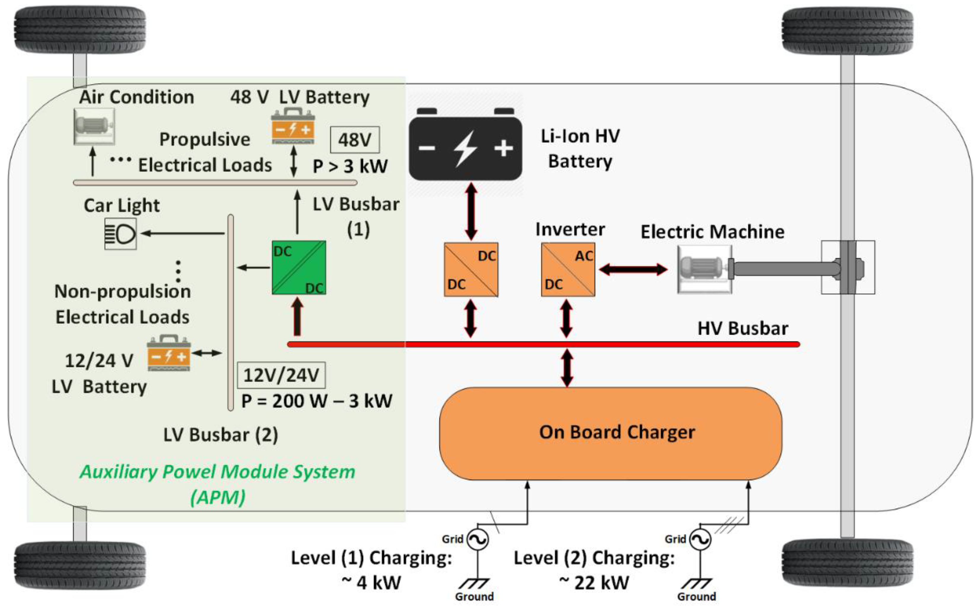
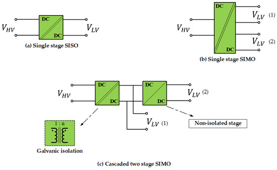
2. APM State-of-the-Art Topologies
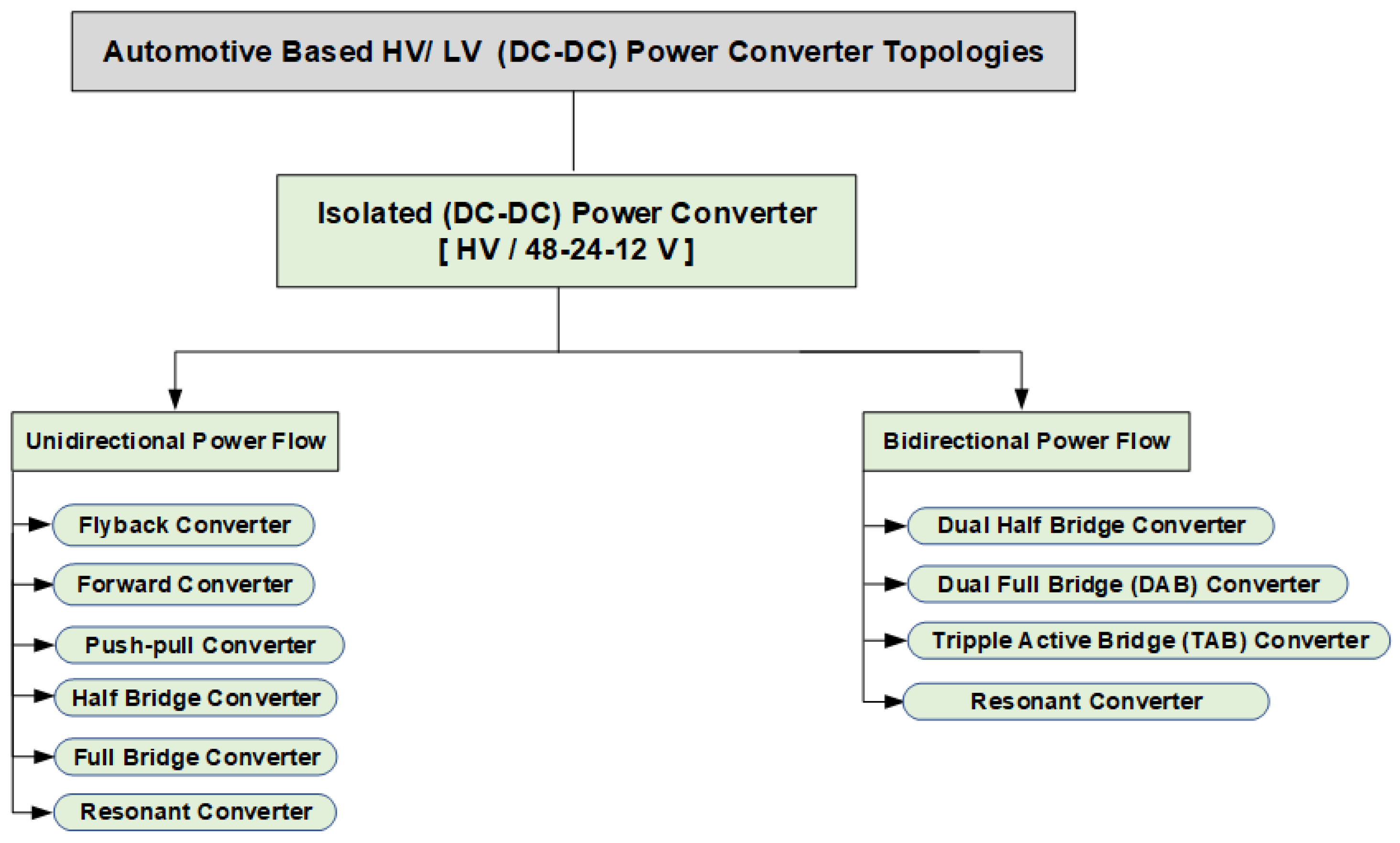
2.1. Unidirectional HV-LV Isolated DC-DC Converters
-
a transformer for galvanic isolation
-
a switching element on the HV battery side to control the power flow and output voltage
-
a passive rectification stage on the secondary side.
2.1.1. Flyback Converter

2.1.2. Forward Converter

2.1.3. Push-Pull Converter
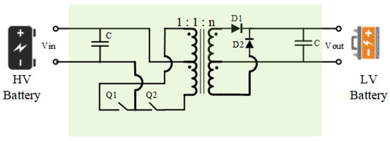
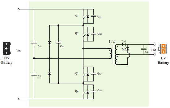
2.1.4. Half-Bridge Converter
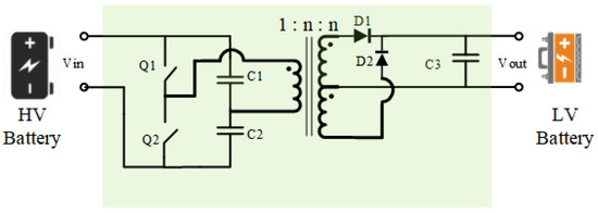
2.1.5. Full-Bridge Converter
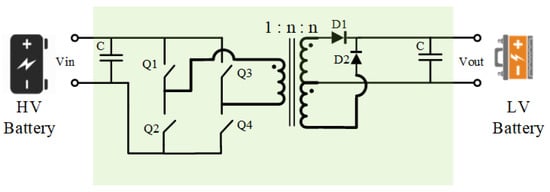
2.1.6. Resonant Converters
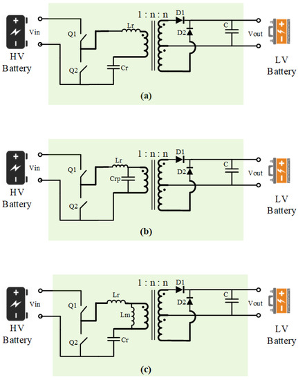
2.2. Bidirectional HV-LV Isolated Power Converters
2.2.1. Dual Half-Bridge (DHB) Converter

2.2.2. Dual Active Bridge (DAB) Converter

2.2.3. Triple Active Bridge (TAB) Converter
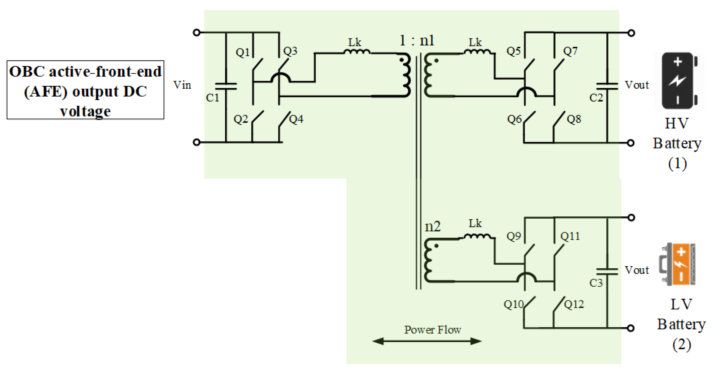
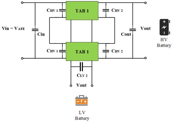
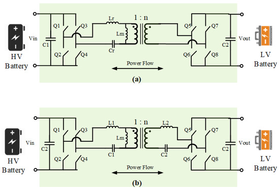
2.2.4. Bidirectional Resonant Converter
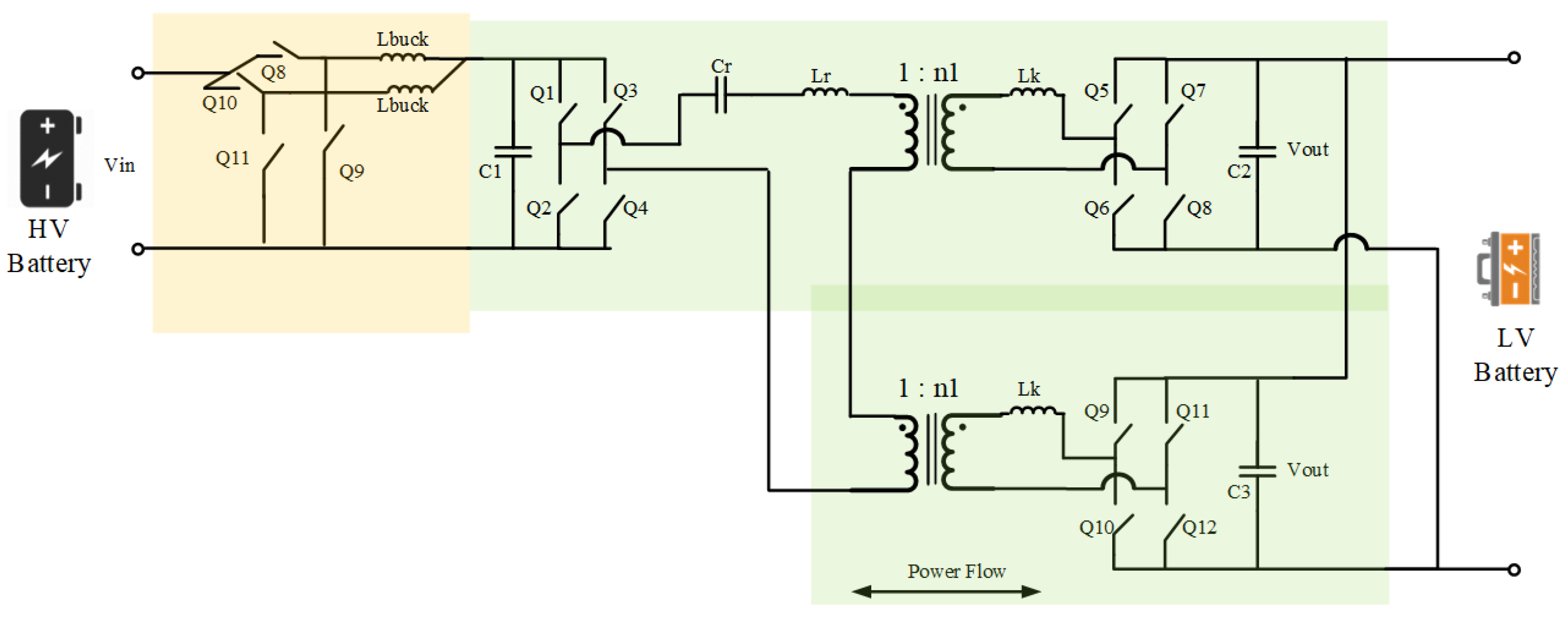
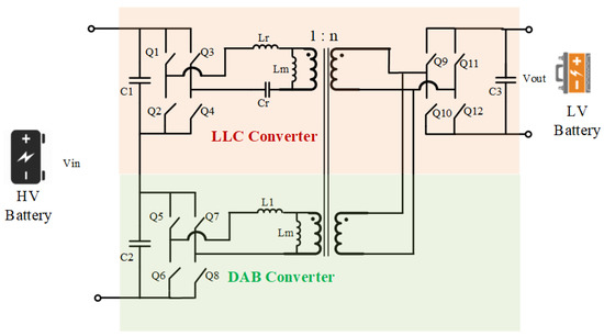
3. Summary of SotA APM Topologies Review
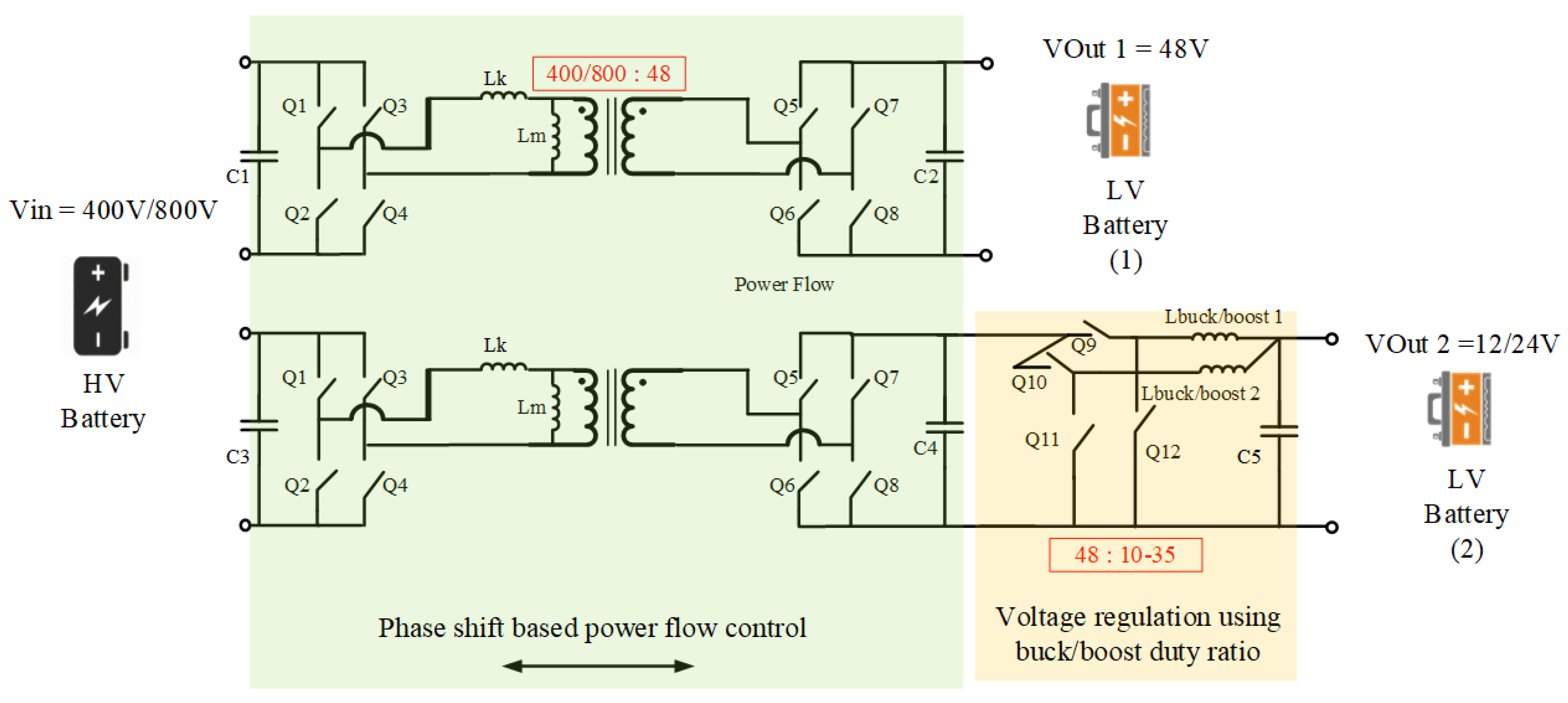
References
- Ghosh, A. Possibilities and challenges for the inclusion of the electric vehicle (EV) to reduce the carbon footprint in the transport sector: A review. Energies 2020, 13, 2602.
- López, I.; Ibarra, E.; Matallana, A.; Andreu, J.; Kortabarria, I. Next generation electric drives for HEV/EV propulsion systems: Technology, trends and challenges. Renew. Sustain. Energy Rev. 2019, 114, 109336.
- Monteiro, V.; Afonso, J.A.; Ferreira, J.C.; Afonso, J.L. Vehicle electrification: New challenges and opportunities for smart grids. Energies 2019, 12, 118.
- Patel, N.; Kumar Bhoi, A.; Padmanaban, S.; Holm-Nielsen, J.-B. Green Energy and Technology Electric Vehicles Modern Technologies and Trends. Available online: http://www.springer.com/series/8059 (accessed on 1 July 2022).
- Yu, G.; Choi, S. Auxiliary Power Module—Integrated EV Charger with Extended ZVS range. In Proceedings of the ECCE 2020—IEEE Energy Conversion Congress and Exposition, Detroit, MI, USA, 11–15 October 2020; pp. 628–632.
- Schäfer, J.; Bortis, D.; Kolar, J.; Schäfer, J.; Bortis, D. Multi-Port Multi-Cell DC/DC Converter Topology for Electric Vehicle’s Power Distribution Networks. In Proceedings of the 2017 IEEE 18th Workshop on Control and Modeling for Power Electronics (COMPEL), Stanford, CA, USA, 9–12 July 2017.
- Tang, Y.; Lu, J.; Wu, B.; Zou, S.; Ding, W.; Khaligh, A. An Integrated Dual-Output Isolated Converter for Plug-in Electric Vehicles. IEEE Trans. Veh. Technol. 2018, 67, 966–976.
- Avila, A.; Garcia-Bediaga, A.; Alzuguren, I.; Vasic, M.; Rujas, A. A Modular Multifunction Power Converter Based on a Multiwinding Flyback Transformer for EV Application. IEEE Trans. Transp. Electrif. 2022, 8, 168–179.
- Ling, Z.; Liang, T.; Yang, L.; Li, T. Design and implementation of interleaved quasi-resonant DC-DC flyback converter. In Proceedings of the International Conference on Power Electronics and Drive Systems, Taipei, Taiwan, 2–5 November 2009; pp. 429–433.
- Zhang, F.; Yan, Y. Novel forward-flyback hybrid bidirectional DC-DC converter. IEEE Trans. Ind. Electron. 2009, 56, 1578–1584.
- Hendra, A.; Hamada, F.; Yusivar, F.; Institute of Electrical and Electronics Engineers. Voltage control in push-pull DC-DC converter using state space averaging PID with soft-start for electric vehicle auxiliary system. In Proceedings of the International Conference on Instrumentation Control and Automation (ICA), Bandung, Indonesia, 31 July–2 August 2019.
- Sayed, K. Zero-voltage soft-switching DC-DC converterbased charger for LV battery in hybrid electric vehicles. IET Power Electron. 2019, 12, 3389–3396.
- Duan, C.; Bai, H.; Guo, W.; Nie, Z. Design of a 2.5-kW 400/12-V High-Efficiency DC/DC Converter Using a Novel Synchronous Rectification Control for Electric Vehicles. IEEE Trans. Transp. Electrif. 2015, 1, 106–114.
- Hou, R.; Emadi, A. Applied Integrated Active Filter Auxiliary Power Module for Electrified Vehicles with Single-Phase Onboard Chargers. IEEE Trans. Power Electron. 2017, 32, 1860–1871.
- EPC Company. Boosting Power Density in 48 V to 5-12 V DC to DC Converter Using EPC2053, with up to 25 a Output; EPC Company: Sandpoint, ID, USA, 2018.
- EPC Company. APPLICATION BRIEF: AB016 eGaN® FETs and and ICs for Automotive DC-DC Applications eGaN® FETs and ICs for Automotive DC-DC Applications EFFICIENT POWER CONVERSION 48 V IN to 12 V OUT for Mild Hybrid Power; EPC Company: Sandpoint, ID, USA, 2022.
- Institute of Electrical and Electronics Engineers. Tenn. Electrical Manufacturing Expo. In Proceedings of the Electrical Insulation Conference and Electrical Manufacturing & Coil Winding Conference, Nashville, TN, USA, 22–24 October 2007.
- Chakraborty, S.; Vu, H.; Hasan, M.; Tran, D.; el Baghdadi, M.; Hegazy, O. DC-DC converter topologies for electric vehicles, plug-in hybrid electric vehicles and fast charging stations: State of the art and future trends. Energies 2019, 12, 569.
- Lipu, M.S.H.; Faisal, M.; Ansari, S.; Hannan, M.A.; Karim, T.F.; Ayob, A.; Hussain, A.; Miah, M.S.; Saad, M.H.M. Review of Electric Vehicle Converter Configurations, Control Schemes and Optimizations: Challenges and Suggestions. Electronics 2021, 10, 477.
- Emrani, A.; Adib, E.; Farzanehfard, H. Single-switch soft-switched isolated DC-DC converter. IEEE Trans. Power Electron. 2012, 27, 1952–1957.
- Rashid, M.H. Power Electronics Circuits, Devices, and Applications, 3rd ed.; Pearson Education, Inc.: Delhi, India, 2004.
- Batarseh, I.; Wei, H. Power factor correction circuits. In Power Electronics Handbook; Butterworth-Heinemann: Oxfrodm, UK, 2011; pp. 523–547.
- Siwakoti, Y.P.; Forouzesh, M.; Pham, N.H. Power electronics converters-an overview. In Control of Power Electronic Converters and Systems; Elsevier: Amsterdam, The Netherlands, 2018; pp. 3–29.
- Hack, T. Flyback controller improves cross regulation for multiple output applications. In Analog Circuit Design; Elsevier: Amsterdam, The Netherlands, 2015; pp. 497–498.
- Baba, D. Isolated Supply Overview and Design Trade-Offs Literature Number: SNVA603 POWER Designer Expert tips, Tricks, and Techniques for Powerful Designs Isolated Supply Overview and Design Trade-Offs; Texas Instruments: Dallas, TX, USA, 2009.
- Severns, R. The history of the forward converters. Switch. Power Mag. 2000, 1, 20–22.
- Habumugisha, D.; Chowdhury, S.; Chowdhury, S.P. A DC-DC interleaved forward converter to step—Up DC voltage for DC Microgrid applications. In Proceedings of the IEEE Power and Energy Society General Meeting, Vancouver, BC, Canada, 21–25 July 2013.
- Roasto, I.; Vinnikov, D.; Lehtla, T. Analysis of capacitor-related mid-voltage point shift problems in high-voltage half-bridge DC/DC converters. In Proceedings of the 2008 IEEE Power Electronics Specialists Conference, Rhodes, Greece, 15–19 June 2008; pp. 3619–3622.
- Hou, R.; Magne, P.; Bilgin, B.; Emadi, A. A topological evaluation of isolated DC/DC converters for Auxiliary Power Modules in Electrified Vehicle applications. In Proceedings of the Conference Proceedings—IEEE Applied Power Electronics Conference and Exposition—APEC, Charlotte, NC, USA, 15–19 May 2015; Volume 2015, pp. 1360–1366.
- Texas Instruments. Phase Shifted Full Bridge, Zero Voltage Transition Design Considerations; Texas Instruments: Dallas, TX, USA, 2011.
- Baggio, J.E.; Hey, H.; Gründling, H.; Pinheiro, H.; Pinheiro, J.R. Isolated interleaved-phase-shift-PWM DC-DC ZVS converter. IEEE Trans. Ind. Appl. 2003, 39, 1795–1802.
- Zhang, J.; Xie, X.; Wu, X.; Qian, Z. Comparison study of phase-shifted full bridge ZVS converters. In Proceedings of the PESC Record—IEEE Annual Power Electronics Specialists Conference, Aachen, Germany, 20–25 June 2004; Volume 1, pp. 533–539.
- Badstuebner, U.; Biela, J.; Christen, D.; Kolar, J. Optimization of a 5-kW telecom phase-shift dc-dc converter with magnetically integrated current doubler. IEEE Trans. Ind. Electron. 2011, 58, 4736–4745.
- Deshmukh, S.; Iqbal, A.; Islam, S.; Khan, I.; Marzband, M.; Rahman, S.; Al-Wahedi, A.M. Review on classification of resonant converters for electric vehicle application. Energy Rep. 2022, 8, 1091–1113.
- Koscelnik, J.; Frivaldsky, M.; Prazenica, M.; Mazgut, R. A Review of Multi-Elements Resonant Converters Topologies. In Proceedings of the 10th International Conference, Rajecke Teplice, Slovakia, 19–20 May 2014; pp. 312–317.
- Salem, M.; Yahya, K. Resonant Power Converters. Available online: www.intechopen.com (accessed on 15 September 2022).
- Yu, S.-Y.; Chen, R.; Viswanathan, A. Power Supply Design Seminar Reproduced from 2018 Texas Instruments Power Supply Design Seminar SEM2300, Topic 1 TI Literature Number. 2018. Available online: www.ti.com/psds (accessed on 25 September 2022).
- Zhou, X. A High Efficiency High Power-Density LLC DC-DC Converter for Electric Vehicles (EVs) On-Board Low Voltage DC-DC Converter (LDC) Application; IEEE: New York, NY, USA, 2020.
- Texas Insturments. BI-Directional, Dual Active Bridge Reference Design for Level 3 Electric Vehicle Charging Station; Texas Instruments: Dallas, TX, USA, 2019.
- Rodriguez-Rodriguez, J.; Salgado-Herrera, N.; Torres-Jimenez, J.; Gonzalez-Cabrera, N.; Granados-Lieberman, D.; Valtierra-Rodriguez, M. Small-signal Model for Dual-active-bridge Converter Considering Total Elimination of Reactive Current. J. Mod. Power Syst. Clean Energy 2021, 9, 450–458.
- Daneshpajooh, H.; Bakhshai, A.; Jain, P. Optimizing Dual Half Bridge Converter for Full Range Soft Switching and High Efficiency. In Proceedings of the IEEE Energy Conversion Congress and Exposition: Energy Conversion Innovation for a Clean Energy Future, ECCE 2011, Phoenix, AZ, USA, 17–22 September 2011; pp. 1296–1301.
- Hou, R.; Emadi, A. Dual active bridge-based full-integrated active filter auxiliary power module for electrified vehicle applications with single-phase onboard chargers. In Proceedings of the Conference Proceedings—IEEE Applied Power Electronics Conference and Exposition—APEC, Long Beach, CA, USA, 20–24 March 2016; pp. 1300–1306.
- Mukherjee, S.; Kumar, A.; Chakraborty, S. Comparison of DAB and LLC DC-DC Converters in High-Step-Down Fixed-Conversion-Ratio (DCX) Applications. IEEE Trans. Power Electron. 2021, 36, 4383–4398.
- Pledl, G.; Tauer, M.; Buecherl, D. Theory of operation, design procedure and simulation of a bidirectional LLC resonant converter for vehicular applications. In Proceedings of the 2010 IEEE Vehicle Power and Propulsion Conference, VPPC 2010, Lille, France, 1–3 December 2010.
- Hillers, A.; Christen, D.; Biela, J. Design of a highly efficient bidirectional isolated LLC resonant converter. In Proceedings of the 2012 15th International Power Electronics and Motion Control Conference (EPE/PEMC), Novi Sad, Serbia, 4–6 September 2012.
- Niu, J.; Wu, X.; Wang, Y.; Jing, L.; Zhang, W.; Tong, Y. Backward Step-Up Control Strategy for Bidirectional LLC Resonant Converter. Energies 2022, 15, 4471.
- Arazi, M.; Payman, A.; Camara, M.; Dakyo, B. Bidirectional interface resonant converter for wide voltage range storage applications. Sustainability 2022, 14, 377.
- Design Guide: TIDM-02002 Bidirectional CLLLC Resonant Dual Active Bridge (DAB) Reference Design for HEV/EV Onboard Charger. 2019. Available online: www.ti.com (accessed on 13 August 2022).
- Yan, Y.H.; Cheng, H.L.; Chan, S.Y.; da Chen, Y.; Chang, Y.N. Design of an isolated bidirectional symmetric resonant converter. Appl. Sci. 2020, 10, 8144.
- Xu, G.; Tang, J.; Zhang, L.; Xiong, W.; Sun, Y.; Su, M. A Hybrid Extended Phase Shift Modulation Strategy for DAB Converter with DC Blocking Capacitor to Extend ZVS Range and Reduce RMS Current. IEEE J. Emerg. Sel. Top Power Electron. 2022, 10, 22184450.
- IEEE Power Electronics Society; IEEE Power & Energy Society; IEEE Industry Applications Society; Institute of Electrical and Electronics Engineers. Proceedings of the 2020 IEEE Transportation Electrification Conference & Expo (ITEC), Chicago, IL, USA, 22–26 June 2020; IEEE: Piscataway Township, NJ, USA, 2020.
- Wang, M.; Pan, S.; Zha, X.; Gong, J.; Lin, W.; Gao, J.; Deng, Q. Hybrid Control Strategy for an Integrated DAB-LLC-DCX DC-DC Converter to Achieve Full-Power-Range Zero-Voltage Switching. IEEE Trans. Power Electron. 2021, 36, 14383–14397.
- Repecho, V.; Olm, J.M.; Grino, R.; Doria-Cerezo, A.; Fossas, E. Modelling and Nonlinear Control of a Magnetically Coupled Multiport DC-DC Converter for Automotive Applications. IEEE Access 2021, 9, 63345–63355.


