1. Introduction
The automotive sector is exponentially changing towards more electrification. This can be seen in the increased global EV sales in the past 10 years. The main reason behind these significant changes in the transportation sector is to face the inevitable climate change problem due to greenhouse gas (GHG) emissions [
2,
3,
4]. As a result, intensive research in the electrification of the transportation sector has been conducted in many fields. The main research focus is to improve the efficiency and reliability of battery electric vehicles (BEVs) to be more efficient and cost-effective for future customers.
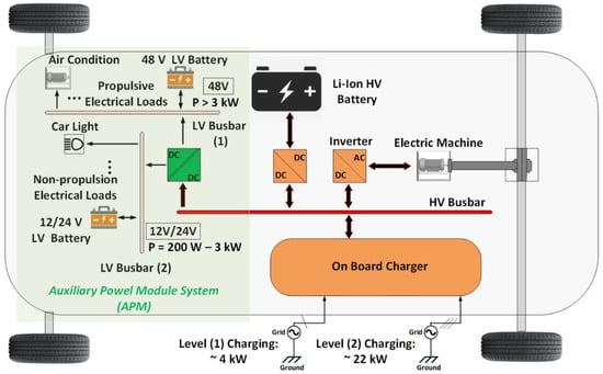
The HV lithium-ion battery is considered the primary energy source for all the BEV electrical loads [
5], including the main propulsion system of the vehicle and the auxiliary loads inside the vehicle. In other words, to supply power to the different LV auxiliary loads, the HV battery voltage needs to be stepped down to different LV levels according to BEV’s E/E architecture. For this reason, an isolated DC-DC converter known as the auxiliary power module (APM) is an essential component in an EV’s E/E architecture, as shown in
Figure 1 [
5].
Figure 1. EV‘s E/E architecture (edited from [
2]).
2. APM State-of-the-Art Topologies
The APM in an EV could be either a standalone system or a secondary auxiliary output from the onboard charger (OBC) system [
14,
58,
62]. However, when the APM power rating is 6 kW or higher, having the OBC and the APM in one system will result in high cost, complexity, and lower reliability [
63].
In this section, different single-input-single-output (SISO) and single-input-multiple-output (SIMO) isolated DC-DC converter topologies for an APM are reviewed.
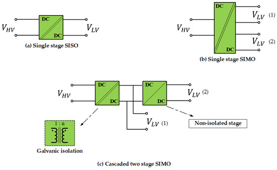
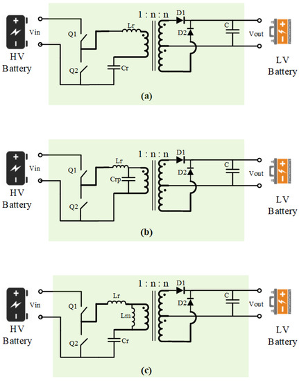
Figure 2 shows the different architectures of the SISO- and SIMO-isolated DC-DC converters. The simplest architecture for a SISO APM is to utilize a single isolating transformer with HV-LV stepping-down ratio, as shown in
Figure 2a [
63,
64,
65,
66,
67,
68,
69]. For SIMO architecture, the first solution according to the literature is to use a single-stage three-winding transformer with two output terminals [
58,
62]. The second solution for a SIMO APM is by using two cascaded stages. The second stage could be implemented as a non-isolated stage to convert the 48 V intermediate voltage to 12 V. This reduces the weight and cost of the system [
70,
71].
Figure 2. APM architectures: (a) single-stage SISO, (b) single-stage SIMO, and (c) cascaded two-stage SIMO.
In the literature, isolated DC-DC converter topologies have been classified in different ways [
25,
72,
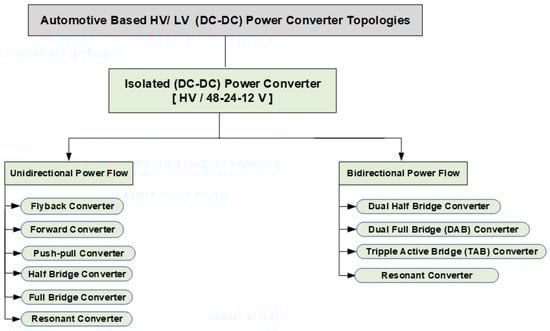
73]. Herein, the isolated HV-LV DC-DC converter topologies have been reviewed and categorized according to their capability to control the power flow either as a unidirectional or a bidirectional converter for EV applications.
Figure 3 demonstrates an overview of the isolated HV-LV DC-DC converter topologies covered here. However, most unidirectional converter topologies can be converted to bidirectional topology by replacing the output diode-based rectification stage with switches-based synchronous rectifiers, which improves the system efficiency with the tradeoff of cost and control complexity [
68]. Nevertheless, the researchers evaluate the topologies according to their efficiency, power density, the complexity of the control, and the number of switching elements in the topology.
Figure 3. Classification of isolated HV-LV APM DC-DC converter topologies.
2.1. Unidirectional HV-LV Isolated DC-DC Converters
A unidirectional switched mode isolated DC-DC converter topology has to include the following [
74]:
-
a transformer for galvanic isolation
-
a switching element on the HV battery side to control the power flow and output voltage
-
a passive rectification stage on the secondary side.
In this section, the most common unidirectional topologies have been reviewed.
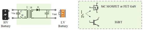
2.1.1. Flyback Converter
The flyback converter is one of the most frequently used topologies in the automotive industry due to its simplicity [
63,
72,
74,
75]. As seen in
Figure 4, the converter is composed of one switch, one transformer, one rectifying diode, and two filter capacitors. It is mostly used for APM HV-12/24 V applications with low power ratings (200 W–1.5 kW) [
63,
64,
76,
77,
78].
Figure 4. Flyback converter [
77].
The biggest advantage of the flyback converter is that it can be extended from a single-stage SISO system to a single-stage SIMO system by simply introducing a secondary winding with a rectification stage [
63,
77].
In [
63], a modular multiport APM converter based on flyback topology was proposed. In this study, cascaded flyback converters connected in series-input-parallel-output were used to reduce the stress on the LV terminal. However, it is stated that one of the disadvantages of the topology is the absence of natural balancing between the ports due to non-magnetic coupling between the core of the transformers. The main drawbacks of flyback converters are high stress on components for HV battery levels of 400–800 V [
74], instability issues in the controller when operating in continuous conduction mode (CCM) [
75], and the duty cycle must be limited to a minimum value that allows the demagnetization of the transformer core to avoid the saturation effect [
75,
79].
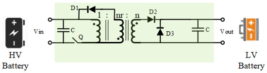
2.1.2. Forward Converter
The forward converter resolves the limited duty cycle constraint of the flyback converter by including a third tertiary winding and a diode in the topology, as shown in Figure 5.
Figure 5. Forward converter [
80].
During the off periods of the Q switch, the tertiary winding provides a path for demagnetizing the current through diode D1 and resetting it to zero [
75,
80]. As a drawback, this rotating current generates heat losses in the system. Similarly to the flyback converter, the forward converter is ideally used for HV-LV APM with a low power rating (maximum 200 W) [
74]. In addition, it must operate at a maximum duty cycle of 50% to give time for the transformer demagnetization process [
79].
In [
65], a bidirectional hybrid topology was proposed with forward and flyback converters connected in series-input-parallel-output. The converter topology was tested on a 150 V–15 V APM application. The topology showed a poor efficiency of 90%. In addition, reverse power control from the LV side to the HV side can be done only if the HV bus is less than a specific value. Moreover, the main drawback of the forward converter topology is the huge leakage inductance of the three-winding transformer, which contributes to a high transient current while operating at a high switching frequency [
81].
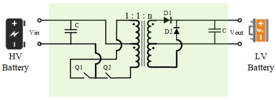
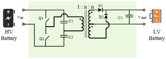
2.1.3. Push-Pull Converter
The push-pull converter is an evolution of the forward converter by replacing the demagnetizing tertiary coil and the diode with an inverter coil and a switch, as shown in
Figure 6. The converter has two modes of operation (push and pull) [
77]. During the push mode operation, switch Q1 is turned on, and the current flows from the HV battery side to the transformer winding, while during the pull mode operation, the switch Q2 is turned on, and the power flows from the transformer to the HV battery.
Figure 6. Push-pull converter [
75].
The transformer size of a push-pull converter can be smaller than forward and flyback converters for certain power levels because the transformer core is used in quadrants 1 and 3 of the BH-loop curve [
79].
In [
66], a 1 kW rated push-pull converter was designed for a 400 V–24 V APM application. One of the disadvantages of the push-pull converter is that the blocking voltage on each switch is 2 times the HV battery voltage. In [
66], a snubber circuit was used to reduce the switching spikes on the switch, which decreased the overall efficiency of the converter. In addition, in [
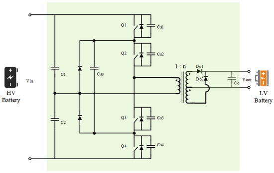
67], the performance of a 500 W push-pull APM is analyzed, which has been used in Toyota Prius cars for a 200 V–12 V APM application. To reduce the voltage stress on the switches, 4 IGBT switches on the primary side with a three-level topology were proposed. Nevertheless, the topology showed a poor efficiency of 90%.
Figure 7 shows the proposed topology in [
67].
Figure 7. ZVS three-level APM DC-DC converter [
67].
To summarize, flyback, forward, and push-pull converter topologies are not favorable for APM applications with 800 V future EV voltage standards, as their high switching voltage stress could cause insulation problems, low efficiency, and instability of the controller.
2.1.4. Half-Bridge Converter
The half-bridge converter uses two switches on the primary side of the isolating transformer, as shown in
Figure 8. Two splitting capacitors are used on the primary side of the transformer, so the voltage across the primary side of the transformer is always half of the HV battery. These splitting capacitors limit the maximum blocking voltage of each switch to input HV (VHV) and not 2 ×VHV. This gives an advantage to the half-bridge converter and allows it to be used for higher power ratings [
77].
Figure 8. Half-bridge converter [
75].
In [
62], a SIMO converter was presented as an application of integrated OBC and APM in one system using a half-bridge topology. The APM was designed for the 400 V–12 V APM application, with a rated power of 500 W. The maximum efficiency of the converter was 94%. As mentioned earlier, the main disadvantage of integrated OBC and APM topology is the huge 3-winding transformer and capacitor ratings. In addition, the topology contains a high number of semiconductors, which adds complexity and cost to the control of the topology.
The main drawback of the half-bridge converter topology is the mismatch in the splitting capacitors due to manufacturer tolerance or environmental effects. As a result, the voltage across them will not be identical, and the current-control mode will worsen the voltage imbalance, eventually causing one capacitor to discharge to zero and stopping the converter [
79,
82]. In addition, the half-bridge converter has low efficiency due to the high conduction losses.
2.1.5. Full-Bridge Converter
The full-bridge converter is the most favorable topology for high power rating DC-DC converters with high power density [
83]. The converter topology, as shown in
Figure 9, reduces the current stress in the switches to half in comparison to the half-bridge topology. In addition, it can easily be operated at high switching frequency while employing the soft switching ZVS technique via the phase shift modulation technique [
48,
84,
85].
Figure 9. Full-bridge converter [
83].
Generally, the main advantage of the phase-shift full-bridge (PSFB) converter topology is its ability to control the converter output voltage by controlling the phase shift between the two converter legs. In addition, parasitic capacitors are used to facilitate the resonance transition of power between the transformer primary and secondary while approving soft switching [
48,
84,
85].
In [
86], a full-bridge APM was designed for a 400 V–48 V application with a high-power density (9 kW/L). Furthermore, in [
69], another APM was proposed based on PSFB topology for 400 V–12 V application. The converter was rated at 2 kW with a maximum efficiency of 95%.
2.1.6. Resonant Converters
A resonant unidirectional isolated DC-DC converter is a conventional isolated converter with added capacitive elements either in series (series resonant converter (SRC)) or in parallel (parallel resonant converter (PRC)) to the transformer’s primary side winding. This series/parallel connection between the transformer leakage inductance and the added capacitors is called the LC resonant tank [
87]. Furthermore, a multi-resonance converter is a converter with more than two resonant elements, e.g., in the case of including the transformer’s primary magnetizing inductance in the resonant tank design (LLC resonant converter) [
88,
89,
90].
Unlike the previously discussed phase shift-controlled converters, where the voltage transfer ratio is controlled either by the duty cycle of the switch or by the phase shift between the two legs of a full-bridge converter, resonant converters depend on frequency modulation (FM). This makes the control design of such converters complex compared to phase shift-controlled converters [
89].
Figure 10 shows a resonant half-bridge isolated DC-DC converter with three different resonant tank configurations. Lr, Cr, and Crp are the resonant tank elements.
Figure 10. Half-bridge unidirectional DC-DC resonant converter configurations: (
a) series resonant converter, (
b) parallel resonant converter, and (
c) LLC resonant converter [
90].
The main advantage of a resonant converter is that it can easily achieve high efficiency by working at the resonance frequency and approving a wide-range soft switching operation [
90]. ZVS and ZCS are achieved by creating resonance between the switching device and the resonant tank during the turn-on and turn-off instants.
According to [
87], SRC and PRC converters have two main drawbacks. Firstly, SRC requires a wide range of frequency variations to regulate the output voltage. Secondly, PRC suffers from low efficiency and high circulating current at light load conditions. Therefore, he proposed that multi-resonant converters, such as LLC converters, can overcome such limitations.
In [
91], a 3.8 kW LLC unidirectional APM was proposed for 400–14 V application. This can be interpreted as 270 A at 14 V rail. To achieve such a high ampere rating, the author proposed a SISO converter with three-interleaved LLC converters connected in a parallel-input-parallel-output connection. In addition, the author used a full-bridge instead of a half-bridge on the primary side to reduce the voltage stress on switches. The topology showed an efficiency of 96.5% by using the ZVS technique. In addition, the power density was 3 kW/L. However, the topology suffered from a very high number of switching elements (30 switches) and 6 transformers, which adds a huge burden on the cost and the complexity of the control algorithm.
2.2. Bidirectional HV-LV Isolated Power Converters
As mentioned previously, bidirectional power flow functionality is an essential requirement for an APM in modern BEVs. This section reviews bidirectional power-controlled APM topologies.
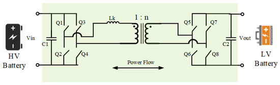
2.2.1. Dual Half-Bridge (DHB) Converter
As shown in
Figure 11, the DHB converter is a modified version of the half-bridge converter topology that replaces the uncontrolled rectification stage with synchronous rectifiers. Using the transformer primary winding’s leakage inductance (Lk), bidirectional power control is achieved by introducing a time delay between the PWM signal of the primary half-bridge and the second half-bridge. This time delay is known in control theory as phase shift bidirectional power flow control [
56,
92].
Figure 11. DHB converter topology [
55].
The converter is recommended to operate a constant duty cycle of 0.5 for each H-Bridge, and the voltage ratio is adjusted by the transformer primary to secondary turns ratio for HV-LV conversion [
56].
In [
55], the author studied the phase shift control techniques of a 290 V–18 V APM to increase the ZVS range of a DHB converter and improve its efficiency. The converter operation was analyzed under different loading conditions. At the end, an optimum phase shift operating strategy was developed under different loading conditions and achieved a maximum converter efficiency of 97%. On the other hand, the author mentioned that one of the drawbacks of the DHB topology is that the splitting capacitors must carry all the transformer current, which results in a bulky capacitor design. In addition, in the case of higher HV battery voltages, the voltage stress on the switches will be high enough to cause a breakdown in the case of voltage overshoots.
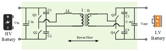
2.2.2. Dual Active Bridge (DAB) Converter
The DAB converter topology shows many advantages over the DHB converter and resonant converters. By comparing different topologies, the DAB converter offers bidirectional power flow with simple architecture, high efficiency, and high power density [
56]. Using the same control concept as the DHB converter, bidirectional power flow control is provided by controlling the phase shift angle between the primary and secondary full bridges, as shown in
Figure 12.
Figure 12. DAB converter topology [
56].
In [
93], a 2.4 kW APM was presented for a 400 V–12 V application. The APM was integrated with the EV’s OBC. The APM was used as an active filter during the HV battery charging mode, which reduced the size of the OBC’s output filter capacitor. One of the disadvantages of the design was the limited ZVS range at the low loading conditions of the LV battery.
In [
57], the DAB converter topology was compared to an LLC resonant converter topology for a 400 V–24 V APM application. In the end, the author concluded that the DAB converter could achieve a reduction in losses by 27% in comparison to the LLC resonant converter.
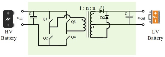
2.2.3. Triple Active Bridge (TAB) Converter
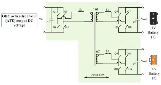
The triple active bridge (TAB) topology is a modified SIMO topology from the DAB converter using a three-winding transformer and a second H-bridge on the secondary side. The TAB converter is shown in Figure 13. The main advantage of this topology is that it provides a simple solution for multiple isolated outputs with a simple control.
Figure 13. TAB converter topology for the OBC + APM system [
58].
In [
58], a multiport/multi-cell (MPMC) DC-DC converter based on TAB converter topology was presented for the EV power distribution network. The converter can be used for both the APM and OBC-isolated DC-DC stages. Each cell of the TAB topology is shown in
Figure 13. By connecting multiple cells in a series-input-parallel-output connection, the APM rating can be increased for high DC voltage and LV current, with minimized losses. Using this concept, the author proposed a 2 kW power rated 500 V–15 V APM design with two TAB cells.
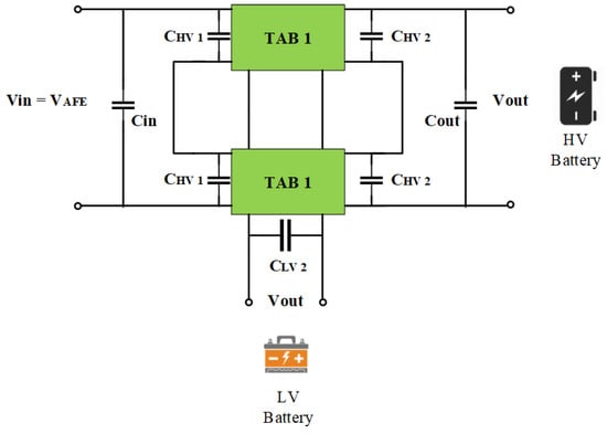
Figure 14 shows the connection of the cells for the OBC + APM system [
58]. The main disadvantage of the topology is that based on the predefined LV network impedance, and the high di/dt, it is required to have low parasitic inductance, which is hard to achieve in HW design.
Figure 14. Multi-TAB cell series-input-parallel-output connection for high battery voltage and high LV current ratings [
58].
2.2.4. Bidirectional Resonant Converter
A bidirectional resonant converter is like the DAB converter architecture with an added LLC or CLLC resonant tanks between the two full bridges [
94,
95,
96,
97,
98].
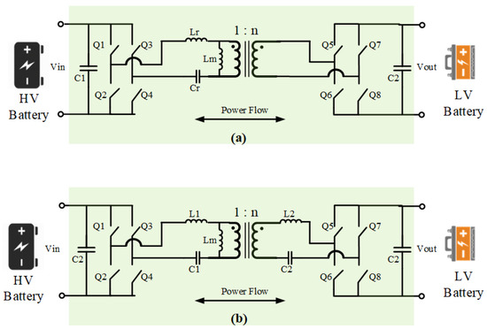
Figure 15 demonstrates the LLC and CLLC resonant converter topologies. According to [
97], the CLLC resonant converter has the advantage of a wider frequency modulation range than the LLC converter. In addition, bidirectional resonant converters have low EMI, high power density, and high efficiency [
98,
99].
Figure 15. Bidirectional resonant converter topologies: (
a) bidirectional LLC resonant converter, and (
b) bidirectional CLLC resonant converter [
97].
Nevertheless, the bidirectional power control of a resonant converter is complex in controller modeling and requires large computation capability. In addition, the phase-shift-time-based control of an APM system with a wide ZVS range can achieve similar results to resonant converters with much simpler control algorithms [
100].
In [
95], a 1.65 kW APM design was presented based on LLC resonant converter topology. The converter achieved maximum efficiency of 97.6% with a wide output LV range from 17 V to 56 V. The study focused on developing an optimum modulation scheme for the LLC converter that approves high-efficiency operation. The main drawback of the topology is the high turn-off currents on the LV side.
In [
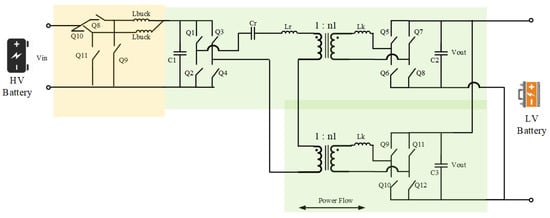
101], a high-power (6 kW peak) APM was designed for a 400 V–12 V application. As shown in
Figure 16, to achieve more than 500 A at 12 V rail, the author implemented a TAB converter topology with two separate transformer cores. The converter was composed of two cascaded systems. The first stage was an interleaved non-isolated buck converter to step down the HV battery voltage to an intermediate voltage. Then, a second stage of the LC resonance converter was implemented. The two transformers were connected in a series-input-parallel-output connection. The topology achieved a peak efficiency of 96%. However, the drawbacks of the topology were the high cost and the intermediate buck stage, requiring the extra controller to achieve ZVS.
Figure 16. Non-isolated interleaved buck + LC resonance converter APM design [
101].
In [
102], the author presented a unique solution for an optimized low-power (80 W) 48 V–5 V APM application using the DAB converter topology with an LLC resonance converter, as shown in
Figure 17. The two converters shared the same magnetic core as the transformer, which reduced the losses. The author implemented a hybrid control strategy for the converter in order to achieve ZVS at full load range at primary side switches, and ZCS at secondary side rectifiers. The gain of the LLC converter is controlled with the switching frequency to distribute the power among the LLC stage and the DAB stage. The converter operating frequency range was 320–400 kHz. The optimized hybrid controller showed maximum efficiency of 96% with minimized output voltage ripple.
Figure 17. Hybrid DAB + LLC DC-DC converter topology [
102].
3. Summary of SotA APM Topologies Review
The recent research effort focused on using DAB and TAB converter topologies. The topologies ensure simple bidirectional power flow control of the APM. In addition, LLC and CLLC resonant converter topologies have been investigated in some papers by using frequency modulation to control the converter’s gain. Furthermore, to ensure high power ratings at the LV rail, a non-isolated interleaved bidirectional converter can be used in cascade with the DAB, TAP, LLC, and CLLC converters.
The main disadvantages of the DAB and TAB converters are the limited ZVS range and the dependency of the ZVS operation on the load condition. On the other hand, the main disadvantage of the frequency-based control of resonance converters is the complexity of the control. Nevertheless, resonant converters can achieve high power density and high efficiency by ensuring ZVS and ZCS techniques. In [
57], the DAB and LLC converter topologies were compared for a 400 V–20 V 330 W APM application. The authors measured the efficiency of the two topologies at a 1 MHz switching frequency. The conclusion was that the DAB converter could achieve higher efficiency than the LLC resonant converter by 27%. This is because the LLC converter peak current is constant at the complete LV load range. However, with the DAB topology, the transformer peak current is proportional to the load level.
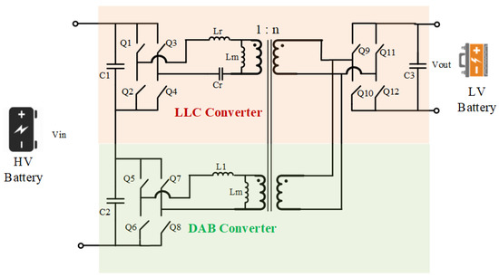
Few pieces of literature have been published in academia for presenting the potentiality of multiport DC-DC converters for EVs’ APM. In [
9], a full-bridge magnetically coupled multiport APM topology was proposed with two outputs of 48 V and 12 V. The control strategy of the converter was validated with a 2.5 kW rated lab prototype.
To conclude,
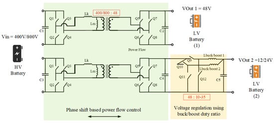
Figure 18 demonstrates the proposed topology for a modular SIMO APM. Firstly, a DAB converter stage can be used for the HV-48 voltage conversion stage. Secondly, an interleaved non-isolated buck-boost converter can be used for the 48–12/24 voltage conversion stage. The second LV port’s voltage can be regulated by controlling the buck-boost stage duty ratio. Multiple buck-boost stages can be connected in a series-input-parallel-output connection to scale the 12/24 V rail power rating. SiC switches can be used in the HV-48 V stage due to the advantage of high breakdown voltage. GaN switches can be used in the non-isolated stage for 48 V–12 V conversion, as shown in the EPC company’s power conversion board [
70]. The GaN switches will ensure a high switching frequency with minimized losses. Furthermore, the design ensures a wide input HV battery range. In the case of 400 V, the converter can be connected in a parallel input connection to reduce current stress. On the other hand, for the 800 V application, the converter can be connected in a series-input connection to reduce voltage stress on switches. The two transformer cores are isolated to isolate the disturbances and failures effect of one LV network on another.
Figure 18. Proposed multiport interleaved APM for a wide input HV range and variable LV network voltage level (e.g., 12 V/24 V).
This entry is adapted from the peer-reviewed paper 10.3390/en16041753