Your browser does not fully support modern features. Please upgrade for a smoother experience.
Submitted Successfully!
 +1 credit
Thank you for your contribution! You can also upload a video entry or images related to this topic.
For video creation, please contact our Academic Video Service.
| Version | Summary | Created by | Modification | Content Size | Created at | Operation |
|---|---|---|---|---|---|---|
| 1 | Mostafa Hassanalian | -- | 6189 | 2023-03-07 06:16:45 | | | |
| 2 | Conner Chen | + 13 word(s) | 6202 | 2023-03-08 03:19:29 | | |
Video Upload Options
We provide professional Academic Video Service to translate complex research into visually appealing presentations. Would you like to try it?
Cite
If you have any further questions, please contact Encyclopedia Editorial Office.
Dinelli, C.; Racette, J.; Escarcega, M.; Lotero, S.; Gordon, J.; Montoya, J.; Dunaway, C.; Androulakis, V.; Khaniani, H.; Shao, S.; et al. Classification of Unmanned Systems. Encyclopedia. Available online: https://encyclopedia.pub/entry/41924 (accessed on 07 July 2026).
Dinelli C, Racette J, Escarcega M, Lotero S, Gordon J, Montoya J, et al. Classification of Unmanned Systems. Encyclopedia. Available at: https://encyclopedia.pub/entry/41924. Accessed July 07, 2026.
Dinelli, Chris, John Racette, Mario Escarcega, Simon Lotero, Jeffrey Gordon, James Montoya, Chase Dunaway, Vasileios Androulakis, Hassan Khaniani, Sihua Shao, et al. "Classification of Unmanned Systems" Encyclopedia, https://encyclopedia.pub/entry/41924 (accessed July 07, 2026).
Dinelli, C., Racette, J., Escarcega, M., Lotero, S., Gordon, J., Montoya, J., Dunaway, C., Androulakis, V., Khaniani, H., Shao, S., Roghanchi, P., & Hassanalian, M. (2023, March 07). Classification of Unmanned Systems. In Encyclopedia. https://encyclopedia.pub/entry/41924
Dinelli, Chris, et al. "Classification of Unmanned Systems." Encyclopedia. Web. 07 March, 2023.
Copy Citation
The autonomous and semi-autonomous multi-agent systems have as much variation and as wide a range of applications as those in the modern mechatronics and robotics fields do. The advance of collaborative swarms of Unmanned Ground Vehicles (UGVs) and drones that are able to operate, navigate, communicate, and even install and assemble “each other” as a symbiotic team will play a critical role in the industry, science, and society in the future
subterranean autonomous exploration
drones
bio-inspired robots
1. Classification of Unmanned Systems
Multi-agent hybrid robotic systems (MAHRSs) can be described as the coupling of two or more robotic systems to complete missions as a team. This concept can be compared to biological symbiosis, defined as “any type of a close and long-term biological interaction between two different biological organisms, be it mutualistic, commensalistic, or parasitic” [1]. While the roles of each robot within the system vary in complexity and importance, the overarching objective of using a multi-part hybrid robotic system is to utilize the specializations of many robotic designs, instead of creating one robot that can accomplish every task as an individual. Therefore, each robot is designed to accomplish a mission-specific objective that is part of a bigger objective. Hence, the term MAHRS encompasses not only the design and function of the individual robotic agents, but also the interfacing, connectivity, and collaboration rules between the robotic agents and the simultaneous (passive/active) operation of these multiple specialized robotic agents in order to design a holistically efficient system. It is vital to utilize this design concept to understand the state-of-the-art Unmanned Ground Vehicles (UGVs) and drones as they can be found in commercial marketplaces, scientific publications, industrial settings, and military applications. To begin with, one must first become familiar with the fundamental classification of the different robots, the nomenclature that exists to define these systems, and the individual functionality of each classification. In the following subsections, single robot systems are reviewed, and specifically UGVs, Unmanned Aerial Vehicles (UAVs) (or drones), and single hybrid UGV–UAV robots (see Figure 1).
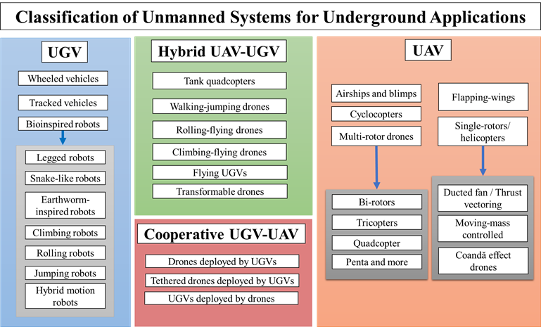
Figure 1. Classification of unmanned systems for underground applications.
2. Unmanned Ground Vehicles (UGV)
2.1. Wheeled Vehicles
Wheeled UGVs are one of the most common types of terrestrial robots deployed for environment exploration, whether it is a well-structured environment or an unknown, harsh environment [2]. Commonly, a UGV is designed to execute a specialized mission based on the output of its exploration and mapping module (see Figure 2). Wheel-based designs come in a wide range of configurations, from the widely used four-wheeled designs to highly complex multi-wheeled rovers designed to traverse highly uneven landscapes [3]. The size, design, and type of the wheels can vary based on the working space and the specialized missions assigned to the UGV. Four-wheeled designs, which are mechanically simpler, enable efficient locomotion on relatively even surfaces. This is the reason that the four-wheeled configuration prevails in most passenger vehicles that are in operation today. By applying torque to the center of each wheel, the robots can move forwards and backward, while by manipulating the steering angle of the wheels or their adjoining shafts, the robots can turn, spin, flip, or perform similar operations.
Wheeled robots have been used in many scientific fields of research, industrial purposes, and military applications [4]. International manufacturers and distributors make various commercial platforms that are available in the marketplace. These platforms can be equipped with a wide variety of sensors, mechanical arms and handlers, and artificial intelligence to aid processes in nearly every industry and application. However, implementing a terrestrial robot to solve a given problem requires researchers or inventors to select between constructing a customized robot or utilizing an existing commercial robot. The choice must be made upon careful consideration of the intended implementation and the specialized missions that will be assigned to the robot. The literature is abundant on such specialized robots, with applications ranging from agricultural monitoring and pruning (see Figure 2a) to extraterrestrial exploration (see Figure 2b).
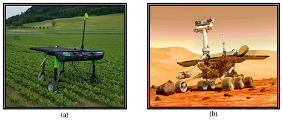
Figure 2. Examples of wheeled UGVs with specialized functionalities: (a) four-wheeled UGV drives through seedlings, picking weeds between rows [5]; (b) six-wheeled UCV traverses Mars’ surface.
The movement of a wheeled robot, and thus its capabilities in each working space, is determined by the number and configuration of the wheels and the wheel axles. For example, a two-wheeled robot with differential drive (see Figure 3a) has three degrees of freedom (DOF), i.e., the position (x, y) and the heading (φ) and two actuators, i.e., the motors on the two wheels [5]. These motors enable the robot to move forwards and backward and rotate in place, but the robot cannot move laterally without first rotating. In comparison, a four-wheeled robot with Ackermann steering has the same three DOF, but two different actuators, i.e., a motor and a steering wheel (see Figure 3b). The motor enables the robot to move forwards and backward, while the steering wheel can only orient the former movement. As a result, the four-wheeled robot can neither rotate in place nor move laterally [5].
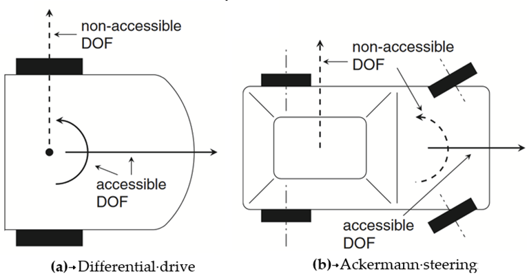
Figure 3. Accessible and non-accessible DOF for differential drive and Ackermann steering robots [5].
When one is constructing a customized wheeled UGV, the design will be focused upon a number of determinative characteristics that include, but are not limited to: the number of wheels, the power source of torque (electric batteries, combustion engines, environmental energy harvesting techniques, etc.), the wheel position on the robot’s frame, the orientation of the wheels during normal operation, removability, retractability, the wheels’ multi-part design (rim and tire combination), material selection, a factor of safety for failure, size, weight, the center of gravity, and the wheel shape (sphere, cylinder, abstract shape, etc.).
Wheel placement and orientation on the platform change how the actuation of the wheels affects the overall motion. Four-wheeled designs with differential drives, such as the one seen in Figure 4, use a simple design to move forward and backward. However, dynamic equations can model the movement of a robot’s movement and the effect of various positions and orientations of the wheels. These models can give useful insights into the various ways to elicit unconventional locomotion, such as the case of the three-wheeled robot depicted in Figure 4.
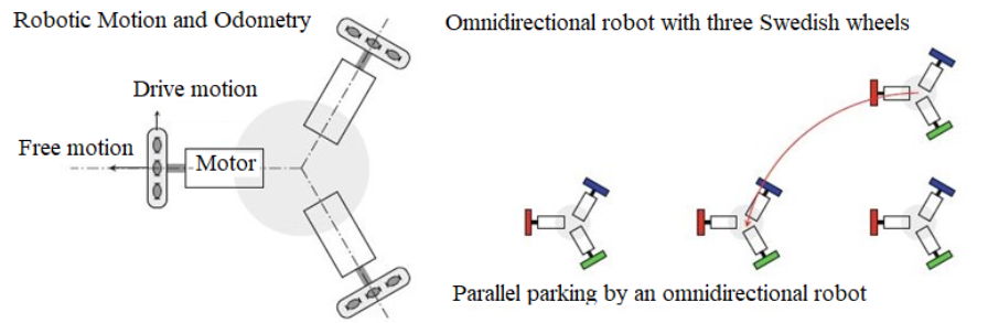
Figure 4. A three-wheeled platform that can actuate each motor about a central axis [5].
An important benefit of utilizing or fabricating wheeled platforms stems from the popularity of these systems. The infinite information and resources from previous implementations and in-depth research and experimentation can be significantly insightful [6]. As one of the oldest and most efficient forms of mechanical locomotion, four-wheeled systems are used today for many applications, and thus, have been readily integrated with odometry sensors and techniques and kinematic analysis that can help to improve various aspects of navigation algorithms (see Figure 5a–c). Despite the inherent operational simplicity of the four-wheeled systems, they are unable to efficiently traverse uneven or slippery terrain, which reduces the necessary wheel-to-ground friction.
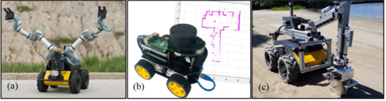
Figure 5. Views of (a) Husky UGV from Clearpath Robotics equipped with two robotic arms (Clearpath Robotics [7]), (b) commercially available wheel-based UGV equipped with LiDAR (SLAM/LIDAR.drone.online), and (c) Husky UGV from Clearpath Robotics equipped with custom fabricated soil manipulator crane arm [8].
2.2. Tracked Vehicles
Tracked UGVs provide a robust alternative to wheeled UGVs [9]. By spreading the weight of the vehicle across a larger surface area, more friction-based adherence to the ground is created. This allows these types of vehicles to operate in uneven and soft-soiled terrain. Although they are slower in speed, the benefits of increased grip and stability are coupled with a stable and simple drive mechanism that allows the tracked vehicles to rotate around themselves (skid-steer locomotion). [10] In most platforms, a track-based UGV consists of two tracked wheel systems on either side, each with multi-directional control, as seen in Figure 6.
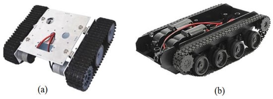
Figure 6. Track-based UGVs are pre-manufactured and sold by commercial distributors both online and in stores. (Walmart, Online Marketplace, Toys and Electronics, 2022).
Track-based suspension is often installed in tracked vehicles to mitigate the impact of ground-to-track interactions. The installation of spring-mass systems or dampeners allows the tracked vehicles to navigate steep or sudden obstacles without damaging the overall drive mechanisms or the sensor modalities on board (see Figure 7 and Figure 8) [11].
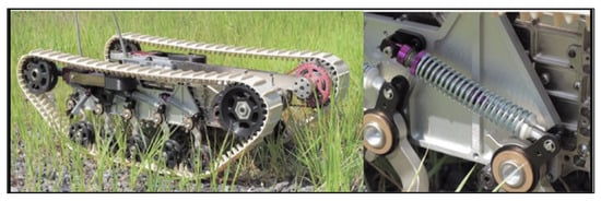
Figure 7. The spring-loaded suspension between tank track drives and supports [11].
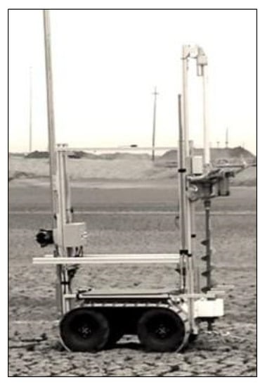
Figure 8. Researchers equip a Husky UGV from Clearpath Robotics with tank tracks that fit over the original UGV wheels [8].
Morphing tracks are tank tracks on a UGV that can change their shape or orientation (see Figure 9). The timing of the change in orientation is often up to the designer of the robot, but this capability to change and morph shapes instantaneously gives these drone agents more tools and degrees of freedom to overcome complex obstacles [12].
Figure 9. View of a morphing-track based robot [12].
2.3. Bio-Inspired Robots
Bio-inspired robots commonly borrow locomotive mechanisms from the natural world to achieve efficient navigation techniques in environments that are similar to the ones that encouraged the natural evolution of living organisms. Most of the bio-inspired robots are small in size, and hence, they do not have the overload capabilities to support complex autonomous functionalities. However, these robots can be used for auxiliary subtasks of an MAHRS’s overall mission. For example, the micro-robots could be used for deploying or reconstructing wireless communication network grids, creating distinctive landmarks or beacons to assist the navigation of the collaborating robotic agents, creating networks for data stations (such as meteorological or hydrological stations), or even assisting in the self-evacuation of trapped humans in subterranean environments. The small size of these robots allows them to carry a single sensor or signaling beacon, while at the same time, it facilitates the storage and deployment of these robots from the larger collaborating robotic agents. Moreover, as nanotechnology, solid state technology, and MEMS advance such robots are becoming increasingly more powerful. The great flexibility of such dynamically deployed networks could be a critical factor for the successful execution of an MAHRS’s mission. The bio-inspired robots examined here include legged robots, snake-like, earthworm-inspired, climbing, rolling, jumping, as well as hybrid motion robots.
2.3.1. Legged Robots
Bio-inspired robots borrow many mechanisms from nature, but one very common means of locomotion that is used is leg-based propulsion. Leg-based designs can be used for walking, running, or even jumping [13][14][15][16]. Leg-based designs can contain any number of legs based on the animals that are simulating, e.g., bipedal ones, quadrupedal ones, hexapods ones, etc. (see Figure 10). Each design achieves a slightly different locomotive goal depending on how many legs are present and how they are arranged.
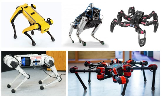
Figure 10. View of leg-based robots.
A spring-loaded scissor jack leg uses multiple joints to accomplish the greater distribution of load across the leg; when they are placed in line and operated by a tank-driven motor, bio-inspired legs can be used even in tank track configurations (see Figure 11) [11].
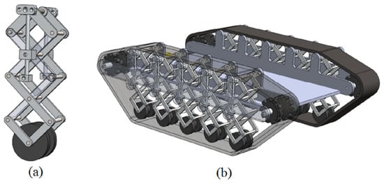
Figure 11. Views of (a) scissor jack leg assembly and (b) scissor jack tank suspension assembly [11].
There are also many approaches to the design of an individual leg. One common realization of a robotic leg includes double-jointed assemblies (one at the hip and one at the knee) [17]. This joint distribution is similar to the leg designs of humans, dogs, cats, etc., ignoring the joint at the ankle. The double-jointed design can be realized with different actuators, both linear and rotational ones, as shown in Figure 12. The benefit of using a linear actuator as the knee joint, known as the pogo stick method, is the simplicity of the system. In this case, there is no geometric work due to the presence of a single angle of the action. The double-rotary joint design, however, is more closely related to the legs of animals. While the design is complicated by the second angle that is introduced, there are more stances, gaits, and types of motion possible with this added dimension of flexibility than there are in the pogo stick design. In Figure 12, views of a robotic leg with one linear actuator at the knee and a rotary actuator at the hip and a leg with two rotary actuators, one at the hip and one at the knee, are shown [17].
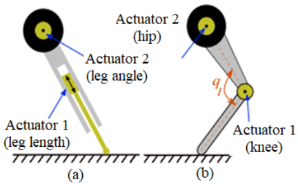
Figure 12. Views of (a) a robotic leg with one linear actuator at the knee and a rotary actuator at the hip and (b) a leg with two rotary actuators: one at the hip and one at the knee [17].
2.3.2. Snake-Like Robots
Among snakes, four primary locomotion modes, also called gaits, have been documented: lateral (serpentine) undulation, concertina, sidewinding, and rectilinear motion [18] (see Figure 13). Concertina locomotion involves a longitudinal wave throughout the snake’s body, which winds up in a sort of ribbon shape, and then extends forward, and the snake repeats the process. Serpentine locomotion is the gait that is most associated with snake movement. During this type of locomotion, the body generates a transverse wave from head to tail and uses this periodic oscillation to propel itself forward. Sidewinding locomotion is the fastest way for a snake to travel, as it involves the sideways stretching and contraction of the body, where only a couple of points on the snake’s body contact the ground at a time. This type of locomotion is often likened to a sort of ‘running’ motion in snakes that are capable of it because of their speed and a small amount of relative ground contact. The last type of snake locomotion, rectilinear or caterpillar locomotion, is a linear mode of transport. This locomotion is best used in cramped environments where sideways undulation is not possible due to the restricted space. Longitudinal stretching and compression make this slow locomotion method possible in the same way that a caterpillar moves, with subtle undulating movements [18].
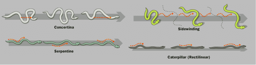
Figure 13. Views of four primary modes of snake locomotion: concertina, serpentine, sidewinding, and rectilinear [18].
Different gaits are desired for different engineering goals when one is designing robots with snake-like locomotion properties. Sidewinder locomotion is likely desired for applications where the robot is expected to speedily transverse a loose, sandy environment or an environment where the ground surface is dangerously hot or otherwise corrosive due to short contact duration. Rectilinear locomotion is necessary for locomotion in cramped environments such as inside slender tunnels or pipes [19]. The types of applications for this type of locomotion include search and rescue missions in tight spaces or pipe inspection for non-destructive testing purposes. Serpentine motion has the advantage of being relatively easy to model using simple actuator units. The locomotion takes advantage of traveling transverse waves, and thus, it can be achieved by creating mechanical oscillations across the body of the robot. This type of bio-inspired serpentine motion is used by the robot shown in Figure 14 [19].
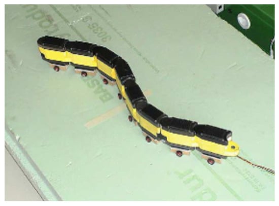
Figure 14. Snake-inspired robot with passive wheels controlled by non-linear oscillators which mimic serpentine locomotion [19].
In 2013, Raytheon Sarcos developed a new generation tandem track snake-like robot (see Figure 15), which is suitable for operations in underground mines [20].
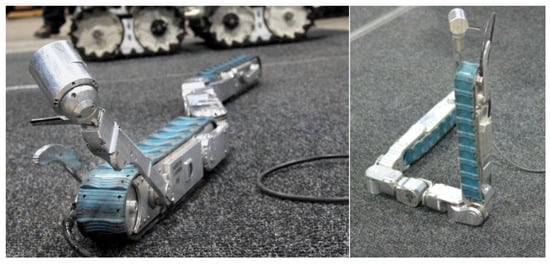
Figure 15. Snake-inspired robot developed by Raytheon Sarco for operations in underground mines [20].
2.3.3. Earthworm-Inspired Robots
Earthworms utilize longitudinal undulation in order to propel themselves forward across surfaces and underground. Their narrow bodies are well adapted to this type of motion, and building robots whose movements are inspired by earthworms has promising applications such as search and rescues, industrial inspections, and medical endoscopy [21].
In order to replicate this method of locomotion, small, linear actuators must be used to replicate longitudinal undulation. As evident in Figure 16, shape memory alloy (SMA) wires are coiled into spring shapes and linked together, then wrapped in a nylon mold. When an electric current is applied to the brass linkages in this SMA skeleton, the spring is heated to induce the Joule effect. This causes the SMA spring to contract, and when the current is shut off, the spring is able to expand gradually, and this process is repeated to create periodical, longitudinal undulating motion [21].
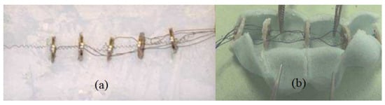
Figure 16. View of (a) shape-memory alloy skeleton of robotic earthworm design and (b) wrapped in a Nylon mold [21].
This SMA skeleton, which is wrapped in the nylon casing, creates the robotic earthworm capable of undulatory travel with four independently controllable modules. Undulatory patterns with a typical frequency of 0.5 Hz is used to create a longitudinal wave that travels across the length of the robot and allows it to propagate through a medium or across a surface. The use of tiny micro-legs on the base of the design allows it to generate enough traction to climb up inclined surfaces with small undulations (see Figure 17) [21].
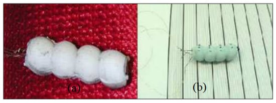
Figure 17. View of robotic earthworm design using shape memory alloy locomotion technology (a) with and (b) without micro-legs [21].
2.3.4. Climbing Robots
Many natural climbing locomotion instances can be found and studied when one is intending to design a robotic climber. Many animals, such as insects, lizards, and amphibians, can easily climb sheer surfaces. Much of their climbing success can be attributed to the natural adhesive effects of their appendages, their lightweight, and the efficiency of their motion. Geckos, for instance, utilize directionally preferential microfibers on their foot pads to generate a frictional force on vertical surfaces, which counteracts its own gravitational force [22]. This is made possible by preloading each foot placement and dragging downwards to generate adhesion. In order to detach each foot pad, gradual peeling is performed to nullify the adhesion in a similar fashion to that of hook and loop fashioners such as VELCRO®. This process is depicted in Figure 18 [22].
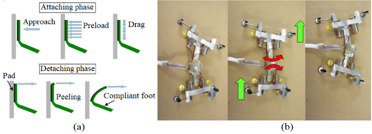
Figure 18. Views of (a) ideal attaching and detaching phase diagram of gecko foot used while climbing and (b) gecko-inspired climbing robot with flexible foot and hip joints and Silly Putty® adhesive foot pads [22].
When smaller, faster robots are required, bio-inspiration may be drawn from the insect or arachnid classes of the animal kingdom. In order to maximize the effectiveness of the climbing robot, considerations need to be made as to what makes their natural counterparts such effective climbers. A high contact-to-weight ratio is desired for adhesion, which is achieved by a low mass and a high leg count. This allows insects such as cockroaches to be very efficient and very fast climbers. Micro-actuators and shape memory alloys can be used to replicate insect-based climbing in robotic applications, such as the one shown in Figure 19 [23].
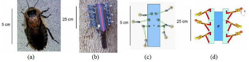
Figure 19. Views of (a) climbing insect, (b) insect-inspired robot, (c) numerical insect model, and (d) numerical robot model. The numerical models were used to compare normal reaction forces and investigate leg configuration, trajectory, and compliances [23].
A four-legged climbing robot “Limbed Excursion Mechanical Utility Robot” called LEMUR was designed and prototyped by NASA’s Jet Propulsion Laboratory and several other institutions. LEMUR uses grippers that are armed with hundreds of tiny, sharp hooks that enable it to climb rock walls and navigate underground spaces [24]. In Figure 20, a view of this climbing robot is shown.

Figure 20. View of a four-legged climbing robot [25].
2.3.5. Rolling Robots
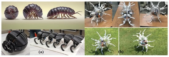
Some robots are designed to be able to move via rolling, which can be especially effective and energy saving when they are traversing certain terrains where gravity aids the direction of travel. Some of them are designed to be completely globular, relying on rolling as the sole method of maneuvering. Rolling robots that use rolling as their sole locomotion method can be classified into three control categories: control by the center of mass, control by variable gyrostatic momentum, and control by deformation [26]. Other hybrid designs are designed to be able to walk and roll, which makes them more similar to the animals they draw inspiration from, such as isopods, armadillos, and rolling spiders (see Figure 21). These robots often involve a process that contracts them into a spherical shape, which is a process called conglobation.
2.3.6. Jumping Robots
Some bio-inspired robots attempt to emulate the jumping motion of many animal species, such as frogs and kangaroos. This method of locomotion may be beneficial to the robot when it is navigating terrain with obstacles that are impossible to traverse with a traditional rolling wheel locomotion method. One of the difficulties of the jumping method of locomotion is designing a robot that remains perfectly balanced throughout each consecutive jump, and extensive testing is needed to find the robot’s center of gravity. Many jumping robots, such as the kangaroo bot shown in Figure 22, utilize movable counterbalances to simulate the tail. This keeps the robot from over-rotating or under-rotating during each jump and sets it up to proceed with the subsequent jump [27].
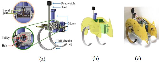
Figure 22. View of a jumping-based bio-inspired kangaroo robot; (a) transmission system of kangaroo robot, (b) CAD drawing of kangaroo robot, and (c) photo of kangaroo robot [27].
2.3.7. Hybrid Motion Bio-Inspired Robots
While many animals have achieved the mastery of certain types of motion, there are also many animals that are capable of multiple modes of transportation. Whether it is climbing and walking, walking and swimming, climbing and flying, or many other combinations, there are natural counterparts to observe for any desired type of locomotion one might have for robotic design. One of the most desirable qualities of a locomotive robot is the ability to traverse both land and water. These amphibious robots can be modeled with inspiration from many amphibious animals, such as otters, crocodilians, salamanders, marine iguanas, and many more. Figure 23 shows a prototype for one such amphibious robot design. Instead of utilizing swimming and walking locomotion modes such as salamanders or crocodilians do, this prototype design uses actuated fins and a wheel that doubles as a propeller when it is underwater [28].
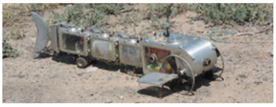
Figure 23. Mechanism design of AmphiRobot-II; prototype of the amphibious robot in the field test [28].
3. Drones
Recently, the mining industry has shown an increased interest in using drones for routine operations in surface and underground mines [29][30][31]. Shahmoradi et al. provided a comprehensive review of the current state of drone technology and its applications in the mining industry. Their study presented the configurations, specifications, and applications of commercially available drones for mining applications [29]. In the following subsections, different drone configurations are discussed including single- and multi-rotors, thrust-vectoring aerial vehicles, moving-mass controlled vehicles, coandă effect drones, flapping, winged drones, airships/blimps, and cyclocopters.
3.1. Single Rotors/Helicopters
Single-rotor drones are useful in the applications of surveying and construction. Due to the greater battery efficiency of powering a single propeller, mono-rotors can lift heavier payloads than multi-rotor drones of the same weight can (see Figure 24). This also creates faster drones, although at the expense of flight stability and directional control fidelity. The biggest challenge to designing a drone with a single rotor is controlling the horizontal flight direction. Using a single rotor enables very easy and efficient vertical flight, but translating itself sideways in a specific direction is difficult to achieve when only a single rotor is used [32][33].
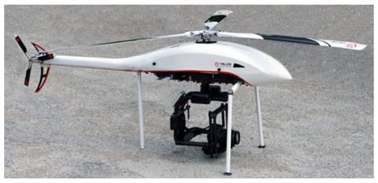
Figure 24. Single-rotor helicopter-style drone used for surveillance [33].
3.2. Ducted Fan/Thrust Vectoring
The challenge of achieving directional horizontal maneuverability can be addressed by utilizing thrust vectoring. Thrust vectoring is a process by which an aerial vehicle can manipulate the direction of thrust from its motor. A mono-rotor drone can accomplish this by including actuated fins below the propeller, which alter and divert the airflow in the desired direction. The mono-rotor drone shown in Figure 25 utilizes this technique and a ducted fan to enable high-speed, controllable, multi-directional flight using a single propeller. The ducted fan enables a more efficient, higher velocity thrust from the propeller by housing it in a cylindrical shroud [32][34][35].
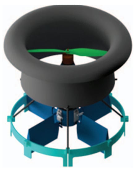
Figure 25. Design of single rotor drone, complete with ducted propeller, four actuated fins, and a structural/landing support [35].
3.3. Moving-Mass Controlled (MMC) Drones
Moving-mass controlled (MMC) drones utilize a unique method of directional control that involves changing the drone’s center of gravity (see Figure 26). Unlike other single-rotor drones, which often use swiveling tilt rotors to control the horizontal movement of the drone, MMC drones often have a fixed rotational axis for the propeller and instead use linear shifts in weight for directional control. Linear actuators, often moving in two spatial dimensions, provide the required shift in the center of mass to achieve the desired directional flight change [32][36].
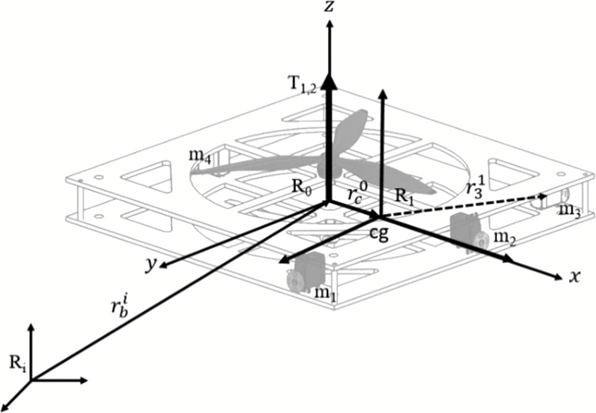
Figure 26. Single-rotor drone controlled by two-dimensional moving masses which direct the drone’s motion by controlling the center of gravity [36].
3.4. Coandă Effect Drones
The Coandă effect, named after the Romanian inventor Henri Coandă, is the tendency of a fluid jet, such as air, to stay attached to a convex surface [32]. This effect can be seen when one is observing the fluid flow around a curved airfoil, causing the flow direction to be altered by the convex surface geometry [37][38]. An illustration of this effect can be seen in Figure 27.
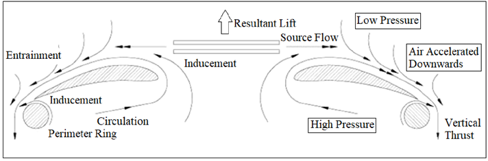
Figure 27. Illustration of the Coandă effect to produce resultant lift as air passes through the center of an airfoil ring and increases velocity as it travels around [38].
This effect is used for certain designs that alter the airflow direction and speed for cooling, such as the Dyson Air MultiplierTM fan, or lift, such as the Aesir Coandă drone shown in Figure 28 [38].
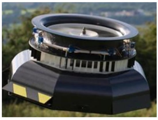
Figure 28. Aesir drone utilizing a single rotor and the Coandă effect for flight [38].
3.5. Multi-Rotor Drones
Besides single-rotor drones or drones that move without rotors, several designs of drones adopt two or more rotors that enable better directional control. In the following subsections, a brief overview of bi-rotors, tricopters, quadcopters, and pentacopters is presented.
3.5.1. Bi-Rotors
As opposed to the more conventional quadcopter design, it is possible to design a bi-rotor drone with tilting rotors to enable directional control. The primary reason that quadcopters are used more often than bi-rotor drones is the appeal of utilizing fixed rotors while still being able to maneuver the drone forwards and backwards, left and right, as well as making it rotate. The bi-rotor does not have this flexibility with fixed rotors, and balance and symmetry must be sacrificed when one is opting the two-rotor configuration. It is worth noting that this configuration still provides more stability with fewer workarounds than the mono-rotor configuration does [32].
One of the main advantages of using a bi-rotor drone design over a quadcopter one is battery efficiency. The tilting mechanisms on each rotor enable the drone to be controlled without much loss of control or stability, but powering only two rotors facilitates significantly longer flight times, nearly doubling the maximum flight duration from about a half hour (as typical in quadcopter flights) to fifty minutes in the case of the V-Coptr Falcon by Zero Zero Robotics, as shown in Figure 29 [39].
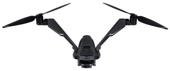
Figure 29. V-Coptr Falcon by Zero Zero Robotics with two tilting rotors [39].
3.5.2. Tricopters
Tricopters, such as the one shown in Figure 30, are drones with three rotors as opposed to four or more. These drones are vastly less popular than quadcopters are for a few key reasons. While reducing the number of rotors from four to three may reduce the weight of the drone, the loss of thrust imposes limitations. The tricopter has a longer battery life than quadcopters do due to the need to power one less rotor, but not by a large enough margin to make up for the many downsides to three-rotor control. The main reason that tricopters have a hard time competing with quadcopters is the difficulty of control arising from the frame’s asymmetry. While quadcopters have four-way symmetry and intuitive solutions to controlling pitch, yaw, and roll, the tricopter does not. Due to the asymmetry of the tricopter, flight control is much more complex than it is with the quadcopter. As a result, numerous studies have been conducted to devise mechanical solutions to controlling altitude, pitch, yaw, and roll. Altitude control and pitch control are relatively straightforward with the tricopter, but unusual combinations of rotor power and servo motors are required to control the drone’s roll and yaw. As an example of these complexities, some controlling techniques are illustrated in Figure 31 [32][40].
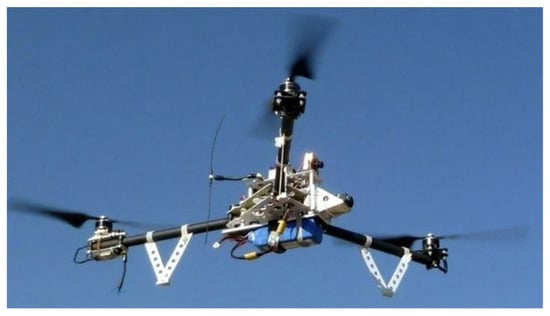
Figure 30. Tri-rotor drone in flight [40].
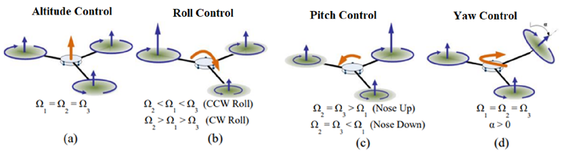
Figure 31. Tri-rotor drone control strategies for (a) altitude; (b) roll; (c) pitch; (d) yaw [41].
3.5.3. Quadcopter
Quadcopters with four individually controlled rotors are the most widely used design for drones. The popularity of this design comes from the ease of control granted by the two axes of symmetry, allowing for pitch, yaw, and roll to be controlled with ease. While the battery efficiency is less appealing compared to the drones with less than four rotors, most commercial quadcopters are often able to sustain flights in the range of thirty minutes. Figure 32 shows a custom-made quadcopter based on a commercial racing frame kit. Common applications for commercial quadcopters include security and surveillance, topographical mapping, emergency responses, infrastructure inspections, and even drone racing [42].
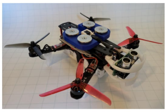
Figure 32. Semi-autonomous precision-docking quadcopter constructed from a racing drone frame with custom sensors and flight controllers [42].
3.5.4. Pentacopters and Others
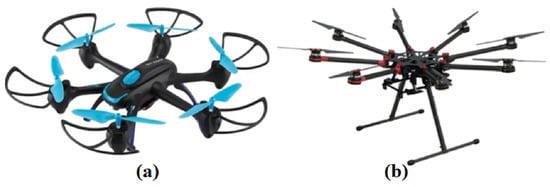
While quadcopters are considered to be the standard drone design for most applications, drones with a higher rotor count exhibit advantages for specific applications despite the disadvantages of an increased weight, size, and cost of the drone, as well as the decrease in battery life and flight time. Drones with a large number of rotors come with the benefit of a higher weight-lifting potential. Although the weight of multi-rotor drones is larger, the added rotors enable it to have a higher overload capacity. As a result, hexacopter and octocopter drones are often used in applications that require them to lift larger payloads, including delivery drone applications such as the hexacopter shown in Figure 33 [32][43].
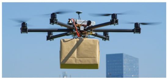
Figure 33. Hexacopter drone used for package delivery [43].
While four-, six-, and eight-rotor drones have many commercial applications, five-rotor pentacopters are very rarely used. This is due to the greatly increased difficulty of piloting a drone with an odd number of symmetries, and the development of piloting algorithms for such symmetries lag compared to those of other drones. Some pentacopters utilize quadrilateral symmetry, with the fifth rotor placed in the design center (see Figure 34a) or used as a frontal propeller (Figure 34b), which allows them to be piloted in a very similar way to traditional quadcopters [32].
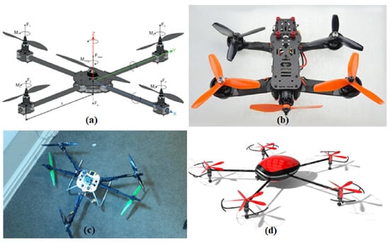
Figure 34. Various pentacopter designs: (a) central upwards rotor on experimental drone design [44], (b) front-facing propeller on Foxtech Screamer Racing Pentacopter [45], (c) experimental ‘dragonfly’ design with four front rotors and a tail for pitch control [46], and (d) a purely hypothetical equidistant rotor design [47].
Although pentacopters are often deemed to be impractical for flight due to the difficulty of controlling them, six-rotor and eight-rotor drones are commercially available for purposes such as surveying and payload delivery (see Figure 35). One of the benefits of six- and eight-rotor drones, besides their higher lift potential, is rotor redundancy. This means that in the event of a rotor failure during flight, the drone can remain airborne, as opposed to a quadcopter, which becomes inoperable in the event of a single rotor failure [32].
3.6. Flapping Wings
Flapping wing drones are inspired by birds or insects and imitate them with the help of mechanical wings to gain altitude and fly in the desired manner (see Figure 36). Flapping wing drones have the potential to offer better maneuverability advantages over those of other drones of the same size [50][51][52][53][54][55][56][57][58][59][60]. Small insect- and hummingbird-inspired drones could potentially be capable of Vertical Takeoff and Landing (VTOL). A disadvantage of flapping wing drones is the complexity of their actuation mechanism.
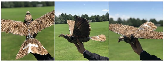
Figure 36. A flapping wing drone that took bio-inspiration from dragonflies [56].
3.7. Airships and Blimps
Unmanned airships rely on lighter-than-air buoyancy for lift, as opposed to rotors or flapping wings. These drones are required to be much larger than traditional quadcopters or flapping wing drones are due to the requirement of large volumes of lifting gas (see Figure 37). A major advantage of airships is that they require a very small amount of battery power to stay gas aloft, and hence, they endure for longer. On the other hand, airships have the major drawback of a low payload capacity despite their size. The large size of airships also creates a lot of drag, which hinders their performance in air currents and prevents them from achieving high speeds [32][61].
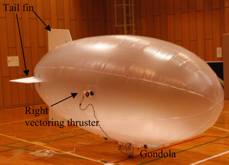
Figure 37. An autonomous airship that uses thrusters and tail fins for control [62].
3.8. Cyclocopters
Cyclocopters generate lift through an arrangement of airfoils that rotate continuously to control lift and thrust (see Figure 38). Configuring the pitch and rotation of the airfoils enable the control of the cyclocopter’s movement [63]. Cyclocopters can come in several configurations, including twin and quad configurations, and they are also capable of VTOL [32][34]. However, two major drawbacks of cyclocopters are their mechanical complexity and the complexity of their control.
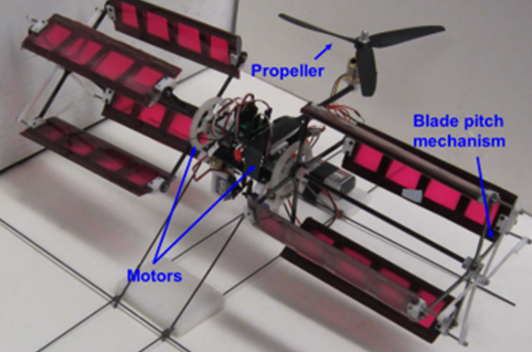
Figure 38. A twin cyclocopter that uses the rotating blade pitch mechanism to produce lift [63].
4. Hybrid Drone–UGV Systems
Hybrid single-agent systems where a UGV can convert to or simultaneously function as a drone, and vice versa, are a popular alternative to expand the capabilities of a single robot. Common examples include tank quadcopters, walking/jumping drones, rolling–flying drones, climbing–flying drones, flying UGVs, and transformable drones.
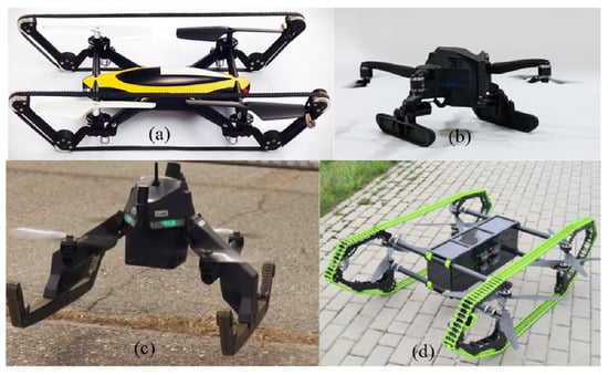
4.1. Tank Quadcopters
One type of unmanned hybrid aerial–terrestrial vehicle is a tank quadcopter, i.e., a quadcopter fitted with powered tank treads, allowing for both all-terrain ground travel and aerial travel. This option allows the unmanned vehicle to navigate and execute missions in a large range of environments. The treads would allow the drone to easily traverse difficult terrain and could be designed to be relatively lightweight compared to a drone with multiple wheels. Treads that wrap all the way around the drone, such as in Figure 39, would also allow the drone to continue ground travel upside down if the vehicle happens to be turned over.
4.2. Walking/Jumping Drones
Walking and jumping drones are both potential concepts for hybrid aerial–ground-based robots (see Figure 40). They would both allow the drone an alternative means of locomoting on the ground; this allows the drones to traverse terrain without flying, which can save the battery power. A drawback to walking/jumping drones is that the drone has to use additional battery power to lift the added weight of the walking/jumping mechanism [68].
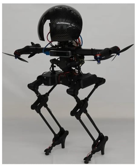
Figure 40. LEONARDO, the walking, hopping, flying drone, is modeled after birds that can both fly and hop in order to navigate telephone lines [68].
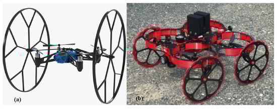
4.3. Rolling–Flying Drones
Another interesting concept for a hybrid aerial–ground-based robot is a rolling–flying drone such as the one in Figure 41. It is similar in concept to a flying UGV; however, this concept focuses more on the drone aspect than it does on the UGV aspect. A rolling drone is advantageous because it has the ability to roll on terrain, whenever possible, which allows it to use less battery power while it is travelling. A drawback of rolling–flying drones is that flying requires more power because it has to lift the additional weight of the rolling mechanism.
4.4. Climbing–Flying Drones
Climbing–flying drones are designed with the ability to climb obstacles or walls if they landed on or near them. The climbing functionality allows the drones to climb over difficult terrain or obstacles instead of flying over the obstacles, and hence, it reduces energy consumption. VertiGo, shown in Figure 42, uses a bi-rotor configuration to assist the drone with climbing walls [72].
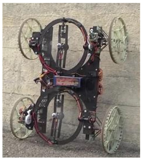
Figure 42. VertiGo, a drone developed by Disney’s research team, is an example of a drone that is capable of scaling walls by using four gripping wheels and a bi-rotor drone, which allows flight and maintains traction on walls [72].
4.5. Flying UGVs
Flying UGVs are another possible hybrid aerial–ground system. Unlike rolling–flying drones or tank quadcopters, the UGV is the primary focus of this type of transformable autonomous agent (see Figure 43). The flight capability of the UGV allows the agent to fly over terrain that is impassable to the UGV’s locomotion mechanism. However, a major drawback of a flying UGV is the higher power consumption due to the rotors having to lift the entire weight of the UGV. This can be mitigated by keeping the UGV’s flights short in duration.
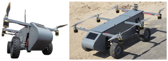
Figure 43. Advanced Tactics Panther Drone is one of the first unmanned ground vehicles (UGVs) capable of flight in addition to terrestrial travel. The UGV uses four powered wheels, as well as four rotors that act as a quadcopter with pitch and roll control [73].
4.6. Transformable Drones
Transformable robots are designed to be able to alter their configuration or shape. Many of them consist of smaller modular components that can be assembled in various manners, as shown in Figure 44. Others have hinges or sections that can move dynamically, allowing the drone to change shape. The ability to transform can be beneficial since it allows the drone to adapt its configuration according to the unique needs of the environment in which the drone operates, allowing it to adapt to dynamic environments.
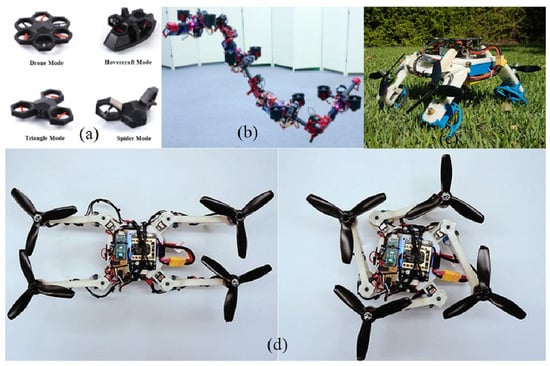
Figure 44. View of (a) Airblock transformable drone is an example of a modular transformable drone that consists of a central core and six modular rotor blocks, which can be rearranged into different flight and ground travel modes, as seen above [74], (b) DRAGON, which is somehow an acronym for the tongue-twisting description “Dual-Rotor Embedded Multilink Robot with the Ability of Multi-Degree-of-Freedom Aerial Transformation,” [75], (c) this drone can transform into a tiny car to slide under small gaps [76], and (d) morphing design for quadrotors [77].
References
- Louie, A.H. Relational biology of symbiosis. Axiomathes 2010, 20, 495–509.
- Borges, P.; Peynot, T.; Liang, S.; Arain, B.; Wildie, M.; Minareci, M.; Lichman, S.; Samvedi, G.; Sa, I.; Hudson, N.; et al. A Survey on Terrain Traversability Analysis for Autonomous Ground Vehicles: Methods, Sensors, and Challenges. Field Robot. 2022, 2, 1567–1627.
- Lanctot, S.; Herkenhoff, B.; Hassanalian, M. Unmanned Launching & Landing Rover (ULLR) for Moon and Martian Missions on Ice-Caps. In Proceedings of the 2021 ASCEND Conference, Las Vegas, NV, USA, 15–17 November 2021.
- John, T.S. Advancements in robotics and its future uses. Int. J. Sci. Eng. Res. 2011, 2, 1–6.
- Ben-Ari, M.; Mondada, F. Robotic motion and odometry. In Elements of Robotics; Springer: Cham, Switzerland, 2018; pp. 63–93.
- Ni, J.; Hu, J.; Xiang, C. A review for design and dynamics control of unmanned ground vehicle. Inst. Mech. Eng. Part D J. Automob. Eng. 2021, 235, 1084–1100.
- Clearpath Robotics: Mobile Robots for Research & Development. Available online: https://clearpathrobotics.com/ (accessed on 30 December 2022).
- Olmedo, N.A.; Barczyk, M.; Zhang, H.; Wilson, W.; Lipsett, M.G. A UGV-based modular robotic manipulator for soil sampling and terramechanics investigations. J. Unmanned Veh. Syst. 2020, 8, 364–381.
- Gonzalez-De-Santos, P.; Fernández, R.; Sepúlveda, D.; Navas, E.; Armada, M. Unmanned ground vehicles for smart farms. In Agronomy-Climate Change and Food Security; Intech UK: Horwich, UK, 2020; p. 73.
- Blackburn, M.R.; Bailey, R.; Lytle, B. Improved mobility in a multi-degree-of-freedom unmanned ground vehicle. In Unmanned Ground Vehicle Technology VI; Society of Photo Optical: Orlando, FL, USA, 2004; Volume 5422, pp. 124–134.
- Sun, B.; Jing, X. A tracked robot with novel bio-inspired passive “legs”. Robot. Biomim. 2017, 4, 1–14.
- Guo, W.; Qiu, J.; Xu, X.; Wu, J. TALBOT: A Track-Leg Transformable Robot. Sensors 2022, 22, 1470.
- Herkenhoff, B.; Lanctot, S.; Bjorkman, T.; Serda, N.; Hassanalian, M. Preliminary Design Concept of Locust Inspired Jumping Moon Robot Swarm. In Proceedings of the AIAA Propulsion and Energy 2021 Forum, Virtual Event, 9–11 August 2021; p. 3270.
- Western, A.; Cervantes, R.; Dunning, C.; Haghshenas Jaryani, M.; Hassanalian, M. Bioinspired Robot with Walking, Rolling, and Jumping Capabilities for Planetary Exploration. In Proceedings of the AIAA Aviation 2021 Forum, Virtual Event, 2–6 August 2021; p. 2784.
- Herkenhoff, B.K.; Lanctot, S.I.; Fisher, J.M.; Serda, N.; Bjorkman, T.S.; Martinez, V.; Johnsonand, T.; Davis, C.; Yazzie, T.; Vadiee, N.; et al. Preliminary Design Concept of Locust Inspired Jumping Moon Robot Swarm. In Proceedings of the Lunar and Planetary Science Conference, Online, 15–19 March 2021; p. 2754.
- Western, A.; Haghshenas-Jaryani, M.; Hassanalian, M. Golden wheel spider-inspired rolling robots for planetary exploration. Acta Astronaut. 2022, 204, 34–48.
- Rezazadeh, S.; Abate, A.; Hatton, R.L.; Hurst, J.W. Robot leg design: A constructive framework. IEEE Access 2018, 6, 54369–54387.
- Prada, E.; Miková, Ľ.; Surovec, R.; Kenderová, M. Complex kinematic model of snake-like robot with holonomic constraints. In Proceedings of the Mezinárodní Vědecká Konference k Problematice Technologických a Inovačních Procesů Technnológia Europea, Hradec Králové, Czech Republic, 11–14 December 2012.
- Crespi, A.; Badertscher, A.; Guignard, A.; Ijspeert, A.J. AmphiBot I: An amphibious snake-like robot. Robot. Auton. Syst. 2005, 50, 163–175.
- CDC—Mining Contract—Snake Robot for Mine Rescue—NIOSH. Available online: https://www.cdc.gov/niosh/mining/researchprogram/contracts/contract200–2009-30721.html (accessed on 30 December 2022).
- Menciassi, A.; Gorini, S.; Pernorio, G.; Weiting, L.; Valvo, F.; Dario, P. Design, fabrication and performances of a biomimetic robotic earthworm. In Proceedings of the 2004 IEEE International Conference on Robotics and Biomimetics, Shenyang, China, 22–26 August 2004; pp. 274–278.
- Carlo, M.; Metin, S. A biomimetic climbing robot based on the gecko. J. Bionic Eng. 2006, 3, 115–125.
- Saunders, A.; Goldman, D.I.; Full, R.J.; Buehler, M. The rise climbing robot: Body and leg design. In Proceedings of the Unmanned Systems Technology VIII, Kissimmee, FL, USA, 17–20 May 2006; pp. 401–413.
- Uckert, K.; Parness, A.; Chanover, N.; Eshelman, E.J.; Abcouwer, N.; Nash, J.; Detry, R.; Fuller, C.; Voelz, D.; Hull, R.; et al. Investigating habitability with an integrated rock-climbing robot and astrobiology instrument suite. Astrobiology 2020, 20, 1427–1449.
- The First Climbing Robot for Mars–Sciworthy. Available online: https://sciworthy.com/the-first-climbing-robot-for-mars/ (accessed on 30 December 2022).
- Lanctot, S.; Montoya, J.; Dunaway, C.; Flores, C.E.; Barstow, J.; Janney, W.; Eisenberg, S.; Good, F.; Davis, N.S.; Zhang, S.; et al. Pillbug-Inspired Robot with Crawling and Rolling Locomotion Mechanisms for Use on the Lunar Surface. In Proceedings of the AIAA SciTech 2023 Forum, National Harbor, MD, USA & Online, 23–27 January 2023.
- Liu, G.H.; Lin, H.Y.; Lin, H.Y.; Chen, S.T.; Lin, P.C. A bio-inspired hopping kangaroo robot with an active tail. J. Bionic Eng. 2014, 11, 541–555.
- Yu, J.; Ding, R.; Yang, Q.; Tan, M.; Wang, W.; Zhang, J. On a bio-inspired amphibious robot capable of multimodal motion. IEEE/ASME Trans. Mechatron. 2011, 17, 847–856.
- Shahmoradi, J.; Talebi, E.; Roghanchi, P.; Hassanalian, M. A Comprehensive Review of Applications of Drone Technology in the Mining Industry. Drones 2020, 4, 34.
- Shahmoradi, J.; Roghanchi, P.; Hassanalian, M. Design, analysis and prototyping of a spherical drone for underground mines. Int. J. Theor. Appl. Multiscale Mech. 2022, 4, 58–82.
- Mirzaeinia, A.; Shahmoradi, J.; Roghanchi, P.; Hassanalian, M. Autonomous Routing and Power Management of Drones in GPS-Denied Environments through Dijkstra Algorithm. In Proceedings of the 2019 AIAA Propulsion and Energy Conference, Indianapolis, Indiana, 19–22 August 2019.
- Darvishpoor, S.; Roshanian, J.; Raissi, A.; Hassanalian, M. Classifications, configurations, and flight mechanisms of unmanned aerial systems: A review. Prog. Aerosp. Sci. 2021, 121, 100694.
- Han, S. A Guide to the Different Types of Drones & UAS. Everglades University. 5 March 2021. Available online: https://www.evergladesuniversity.edu/blog/guide-different-types-drones-unmanned-aerial-systems/ (accessed on 1 December 2022).
- Hassanalian, M.; Abdelkefi, A. Classifications, applications, and design challenges of drones: A review. Prog. Aerosp. Sci. 2017, 91, 99–131.
- Carholt, O.C.; Fresk, E.; Andrikopoulos, G.; Nikolakopoulos, G. Design, modelling and control of a single rotor UAV. In Proceedings of the 2016 24th Mediterranean Conference on Control and Automation (MED), Athens, Greece, 21–24 June 2016; pp. 840–845.
- Darvishpoor, S.; Jafar, R.; Morteza, T. A novel concept of VTOL bi-rotor UAV based on moving mass control. Aerosp. Sci. Technol. 2020, 107, 106238.
- Mirkov, N.; Rasuo, B. Maneuverability of an UAV with coanda effect based lift production. In Proceedings of the 28th International Council of the Aeronautical Sciences (ICAS), Brisbane, Australia, 23–28 September 2012; pp. 1–6.
- Barlow, C.; Lewis, D.; Prior, S.D.; Odedra, S.; Erbil, M.A.; Karamanoglu, M.; Collins, R. Investigating the use of the Coanda Effect to create novel unmanned aerial vehicles. Microsoft Word–MES_2009_Paper_coanda effect C Barlow D Lewis (soton.ac.uk). In Proceedings of the International Conference on Manufacturing and Engineering Systems, Huwei, Taiwan, 17–19 December 2009; pp. 386–391.
- Lavars, N. Bizarre ‘Bicopter’ Drone Uses Two Tilting Rotors for 50-Minute Flights. Available online: https://newatlas.com/drones/v-coptr-falcon-drone-tilting-50/ (accessed on 20 December 2019).
- Jin, H. Tricopter vs. Quadcopter 2022: Which Is Better for You. Available online: https://lucidcam.com/tricopter-vs-quadcopter/ (accessed on 27 April 2022).
- Yoo, D.W.; Oh, H.D.; Won, D.Y.; Tahk, M.J. Dynamic modeling and control system design for Tri-Rotor UAV. In Proceedings of the 2010 3rd International Symposium on Systems and Control in Aeronautics and Astronautics, Harbin, China, 8 June 2010; pp. 762–767.
- Lukow, S.; Sherman, M.; Gammill, M.; Hassanalian, M. Design and Fabrication of Electromagnetic Attachment Mechanism for a Hybrid Drone for Mars Exploration. In Proceedings of the 2021 AIAA SciTech Forum, Virtual Event, 11–15 & 19–21 January 2021.
- Pilot Institute. Is a Drone with More Rotors Better? Available online: https://pilotinstitute.com/more-rotors-better/ (accessed on 30 December 2022).
- Lenski, P. Design, Construction and Operation of a Pentacopter. Master’s Thesis, Luleå University of Technology, Department of Computer Science, Electrical and Space Engineering, Luleå, Sweden, March 2017.
- Foxtech. Blog–Foxtech Screamer Racing Pentacopter-Preorder. Available online: https://www.foxtechfpv.com/blog/0530-news/ (accessed on 30 December 2022).
- Guitarbob. Dragonfly/Pentacopter Project. Available online: https://www.instructables.com/DragonflyPentacopter-Project/ (accessed on 30 December 2022).
- RedDrone. The Red Drone. (Pentacopter Version.right-Top View). Available online: https://www.123rf.com/photo_37276849_the-red-dronepentacopter-versionrighttop-view.html (accessed on 30 December 2022).
- Night Hawk, Sky Rider. King Soopers—Sky Rider Night Hawk Hexacopter Drone with Wi-Fi Camera—Blue/Black, 1 CT. Available online: https://www.kingsoopers.com/p/skyrider-night-hawk-hexacopter-drone-with-wi-fi-camera-blue-black/0004732355700 (accessed on 30 December 2022).
- Octocopter. Spreading Wings S1000—DJI. DJI Official. Available online: https://www.dji.com/spreading-wings-s1000 (accessed on 30 December 2022).
- Throneberry, G.; Hassanalian, M.; Hocut, C.M.; Abdelkefi, A. Insights on the potential of vibratory actuation mechanism for enhanced performance of flapping-wing drones. Meccanica 2021, 56, 1–16.
- Hassanalian, M.; Abdelkefi, A. Towards Improved Hybrid Actuation Mechanisms for Flapping Wing Micro Air Vehicles: Analytical and Experimental Investigations. Drones 2019, 3, 73.
- Throneberry, G.; Hassanalian, M.; Abdelkefi, A. Insights into Sensitivity of Wing Shape and Kinematic Parameters Relative to Aerodynamic Performance of Flapping Wing Nano Air Vehicles. Drones 2019, 3, 49.
- Ghommem, M.; Hassanalian, M.; Al-Marzooqi, M.; Throneberry, G.; Abdelkefi, A. Sizing process, aerodynamic analysis, and experimental assessment of a biplane flapping wing nano air vehicle. Inst. Mech. Eng. Part G. J. Aerosp. Eng. 2019, 233, 0954410019852570.
- Hassanalian, M.; Abdelkefi, A. Methodologies for weight estimation of fixed and flapping wing micro air vehicles. Meccanica 2017, 52, 2047–2068.
- Hassanalian, M.; Abdelkefi, A.; Wei, M.; Ziaei-Rad, S. A novel methodology for wing sizing of bio-inspired flapping wing micro air vehicles: Theory and prototype. Acta Mech. 2017, 228, 1097–1113.
- Khan, M.M.; Gee, P.; Upshaw, J.; Hassanalian, M. Taxidermy Birds as Platform for Flapping Wing Drones: A Bioinspired Mechanism for Wildlife Monitoring. In Proceedings of the AIAA SciTech 2023 Forum, National Harbor, MD, USA & Online, 23–27 January 2023.
- Martinez-Ponce, J.; Urban, C.; Armanini, S.F.; Agarwal, R.K.; Hassanalian, M. Aerodynamic Analysis of V-Shaped Flight Formation of Flapping-Wing Drones: Analytical and Experimental Studies. In Proceedings of the AIAA SCITECH 2022 Forum, San Diego, CA, USA & Online, 3–7 January 2022.
- Gammill, M.; Hassanalian, M. Aerodynamic Analysis of Manta Ray Inspired Fixed and Flapping-Wing Drones for High Altitude Venus Exploration. In Proceedings of the 2021 ASCEND Conference, Las Vegas, NV, USA, 15–17 November 2021.
- Zint, N.; Silva, H.; Hassanalian, M. Design and Prototyping a Butterfly-Inspired Flapping-Wing MAV: Novel Applications of Drones for Met Gala Fashion Event. In Proceedings of the 2021 AIAA SciTech Forum, Virtual Event, 11–15 & 19–21 January 2021.
- Maestas, S.; Martinez-Ponce, J.; Edwards, N.; Hassanalian, M. Applying Least Square Curve Fitting for Extraction the Birds’ Wing Shapes: Flapping Wing MAVs and Kinematic Optimization. In Proceedings of the 2020 AIAA Aviation Forum, Virtual, 15–19 June 2020.
- Erb, J.; Strauss, E.; Naghdi, M.; Hassanalian, M. Exploration of Venus’ Upper Atmosphere Using an Aqua and Bacteria Inspired Aerial System. In Proceedings of the AIAA SCITECH 2022 Forum, San Diego, CA, USA & Online, 3–7 January 2022; p. 2581.
- Kawano, H. Study of path planning method for under-actuated blimp-type UAV in stochastic wind disturbance via augmented-mdp. In Proceedings of the 2011 IEEE/ASME International Conference on Advanced Intelligent Mechatronics (AIM), Budapest, Hungary, 4 July 2011; pp. 180–185.
- Shrestha, E.; Hrishikeshavan, V.; Benedict, M.; Yeo, D.; Chopra, I. Development of control strategies and flight testing of a twin-cyclocopter in forward flight. In Proceedings of the 70th annual national forum of the American Helicopter Society, Montreal, QC, Canada, 20 May 2014.
- Tank Quadcopter Drone|Uncrate. Available online: https://uncrate.com/tank-quadcopter-drone/ (accessed on 30 December 2022).
- Miniature Hybrid UAS/UGV Introduced|Unmanned Systems Technology. Available online: https://www.unmannedsystemstechnology.com/2020/01/miniature-hybrid-uas-ugv-introduced/ (accessed on 30 December 2022).
- Shapeshifting Pegasus Drone Both Drives and Flies, Now Has Smart Radio (forbes.com). Available online: https://www.forbes.com/sites/sebastienroblin/2021/01/27/shapeshifting-pegasus-drone-both-drives-and-flies-now-has-smart-radio/?sh=6a295650795e (accessed on 30 December 2022).
- Available online: https://dronehub.ai/we-are-proud-to-present-the-huuver-our-new-hybrid-drone-that-flies-and-rides/ (accessed on 30 December 2022).
- Kim, K.; Spieler, P.; Lupu, E.S.; Ramezani, A.; Chung, S.J. A bipedal walking robot that can fly, slackline, and skateboard. Sci. Robot. 2021, 6, eabf8136.
- Goldman, J. Parrot MiniDrone Rolling Spider Review: Inexpensive Drone Fun for Novice Flyers. Available online: https://www.cnet.com/reviews/parrot-minidrone-rolling-spider-review/ (accessed on 30 December 2022).
- Mining & Technology: Drones to Map Underground Areas, Save Time & Improve Safety (mozambiqueminingpost.com). Available online: https://mozambiqueminingpost.com/2018/04/30/mining-technology-drones-to-map-underground-areas-save-time-improve-safety/ (accessed on 30 December 2022).
- Ahmed, S.N. 3D scanning and mapping of underground mine workings using aerial drones. Phys. Can. 2018, 74, 103.
- Biggs, T. Disney Research Creates Drone Car That Can Climb Walls. Available online: https://www.smh.com.au/technology/disney-research-creates-drone-car-that-can-climb-walls-20151231-glx6dd.html (accessed on 30 December 2022).
- Panther. Advanced Tactics Panther Drone Has Completed First Aerial Package Delivery Test. Available online: https://uasweekly.com/2017/03/31/advanced-tactics-panther-drone-completed-first-aerial-package-delivery-test-safe-drive-doorstep-capability/ (accessed on 30 December 2022).
- Moscaritolo, A. Airblock Drone Can Turn into a Hovercraft. Available online: https://www.pcmag.com/news/airblock-drone-can-turn-into-a-hovercraft (accessed on 30 December 2022).
- Zhao, M.; Anzai, T.; Shi, F.; Chen, X.; Okada, K.; Inaba, M. Design, modeling, and control of an aerial robot dragon: A dual-rotor-embedded multilink robot with the ability of multi-degree-of-freedom aerial transformation. IEEE Robot. Autom. Lett. 2018, 3, 1176–1183.
- Drone Can Transform into a Tiny Car to Slide under Small Gaps|New Scientist. Available online: https://www.newscientist.com/article/2204184-drone-can-transform-into-a-tiny-car-to-slide-under-small-gaps/ (accessed on 30 December 2022).
- Falanga, D.; Kleber, K.; Mintchev, S.; Floreano, D.; Scaramuzza, D. The foldable drone: A morphing quadrotor that can squeeze and fly. IEEE Robot. Autom. Lett. 2018, 4, 209–216.
More
Information
Subjects:
Engineering, Aerospace
Contributors
MDPI registered users' name will be linked to their SciProfiles pages. To register with us, please refer to https://encyclopedia.pub/register
:
View Times:
5.1K
Revisions:
2 times
(View History)
Update Date:
08 Mar 2023
Table of Contents


Notice
You are not a member of the advisory board for this topic. If you want to update advisory board member profile, please contact office@encyclopedia.pub.
OK
Confirm
Only members of the Encyclopedia advisory board for this topic are allowed to note entries. Would you like to become an advisory board member of the Encyclopedia?
Yes
No
${ textCharacter }/${ maxCharacter }
Submit
Cancel
Back
Comments
${ item }
|
${ item.createdUser.fullName }
${ item.createdAt }
${ item.vote }
${ item.reply }
Delete
${ reply.createdUser.fullName }
${ reply.createdAt }
${ reply.vote }
Delete
There is no reply to this comment~
${ item.replyTextCharacter }/${ item.replyMaxCharacter }
Submit
Cancel
More
No more~
There is no comment~
${ textCharacter }/${ maxCharacter }
Submit
Cancel
${ selectedItem.replyTextCharacter }/${ selectedItem.replyMaxCharacter }
Submit
Cancel
Confirm
Are you sure to Delete?
Yes
No