Your browser does not fully support modern features. Please upgrade for a smoother experience.
Submitted Successfully!
 +1 credit
Thank you for your contribution! You can also upload a video entry or images related to this topic.
For video creation, please contact our Academic Video Service.
| Version | Summary | Created by | Modification | Content Size | Created at | Operation |
|---|---|---|---|---|---|---|
| 1 | Aziz RACHID | -- | 2360 | 2023-02-25 10:33:44 | | | |
| 2 | Lindsay Dong | Meta information modification | 2360 | 2023-02-27 04:01:47 | | | | |
| 3 | Lindsay Dong | + 4 word(s) | 2364 | 2023-02-27 04:03:10 | | |
Video Upload Options
We provide professional Academic Video Service to translate complex research into visually appealing presentations. Would you like to try it?
Cite
If you have any further questions, please contact Encyclopedia Editorial Office.
Rachid, A.; El Fadil, H.; Gaouzi, K.; Rachid, K.; Lassioui, A.; El Idrissi, Z.; Koundi, M. Electric Vehicle Charging Systems. Encyclopedia. Available online: https://encyclopedia.pub/entry/41655 (accessed on 24 July 2026).
Rachid A, El Fadil H, Gaouzi K, Rachid K, Lassioui A, El Idrissi Z, et al. Electric Vehicle Charging Systems. Encyclopedia. Available at: https://encyclopedia.pub/entry/41655. Accessed July 24, 2026.
Rachid, Aziz, Hassan El Fadil, Khawla Gaouzi, Kamal Rachid, Abdellah Lassioui, Zakariae El Idrissi, Mohamed Koundi. "Electric Vehicle Charging Systems" Encyclopedia, https://encyclopedia.pub/entry/41655 (accessed July 24, 2026).
Rachid, A., El Fadil, H., Gaouzi, K., Rachid, K., Lassioui, A., El Idrissi, Z., & Koundi, M. (2023, February 25). Electric Vehicle Charging Systems. In Encyclopedia. https://encyclopedia.pub/entry/41655
Rachid, Aziz, et al. "Electric Vehicle Charging Systems." Encyclopedia. Web. 25 February, 2023.
Copy Citation
The high-voltage battery is a crucial element for electric vehicles (EVs) traction systems. It is the primary energy source that must be regularly recharged to reach the autonomy declared by the manufacturer. Therefore, an EV charging system is required to ensure the battery charging process.
EV charging system
EV charger standards
bidirectional EV charger topologies
1. Classification and Topologies of EV Charger
1.1. EV Chargers Classification
The high-voltage battery (HVB) is vital for electric vehicles (EVs) traction systems. It is the primary energy source that must be regularly recharged to reach the autonomy declared by the manufacturer. Thus, an EV charging system is required to ensure the battery charging process. This vital component, based principally on power conversion stages, allows the electrical energy transfer between the power grid and EV batteries. Therefore, these EV chargers can be classified according to several criteria, including the charger location, the energy transfer direction, the charger structure, the connection type, and the number of power conversion stages [1][2]. Accordingly, the options for each classification type are described in Table 1 (Figure 1).
Table 1. EV charging systems classification.
| EV Chargers | Description |
|---|---|
| Offboard chargers | All the components required for the EV charging and discharging process are inside the public EV charging station [3][4]. |
| On-board chargers | Some components required for the battery-charging process are embedded inside the EV. |
| Unidirectional chargers | The electrical energy transfer is one-way from the EV charging station to the EV battery. Therefore, only the G2V operation mode is possible. |
| Bidirectional chargers | The electrical energy flow can be from or to the EV battery. Thus, V2X technology can be ensured by this type of charger [5]. |
| Dedicated chargers | All equipment making up the charger is exclusively utilized to guarantee the EV charging or discharging process. |
| Integrated chargers | When the EV is linked to the electricity network, the traction system constituents (Motors, inverters, etc.) are used to guarantee the EV charging or discharging process [6]. |
| Conductive chargers | A dedicated electrical cable links the EV to the electricity network. |
| Wireless Power Transfer Chargers [7] |
It is a contactless charging technology. No cables are utilized between the EV and the electricity network [8]. Instead, the electrical energy transfer is based on electromagnetic induction [9]. Figure 6 illustrates the concept of this EV charger type [10]. Compared with conductive chargers, these inductive chargers present various advantages [11]. Especially the convenience for the user and the intrinsic galvanic insulation, while the cost and the need for custom hardware inside the EV are the main drawbacks [12][13]. |
| Single-stage & Dual-stage chargers |
The first one consists of a single power conversion: only one ac-dc or one dc-dc power converter. The second one involves double power stages: ac-dc and dc-dc power conversions. |
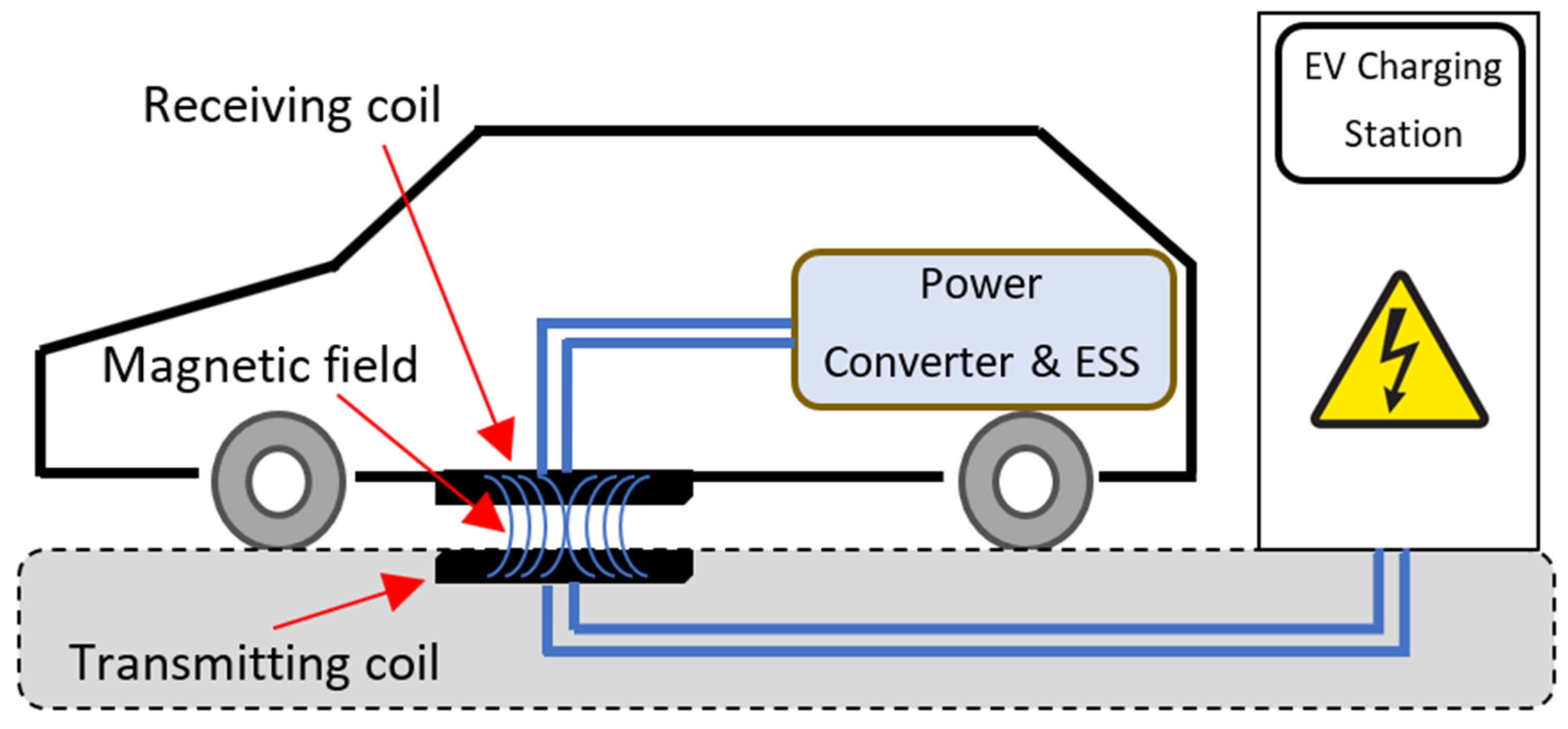
Figure 1. EV wireless charger overview diagram.
1.2. EV Charger Topologies
Figure 2 illustrates available structures which can be implemented for EV charger applications [14][15].
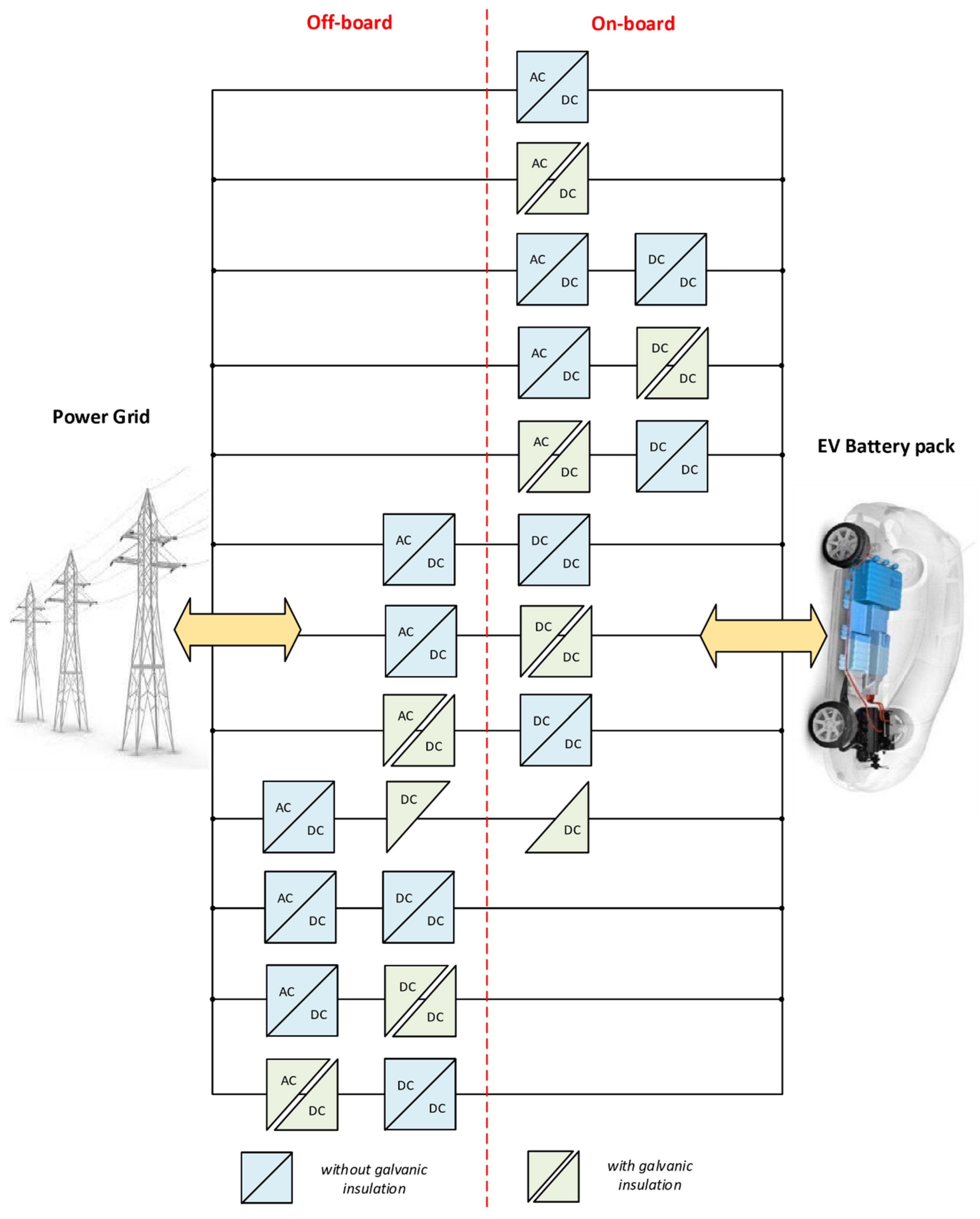
Figure 2. Possible structures for EV charger solutions.
In the dual-stage case, a bidirectional EV charger includes a dc-dc power stage following an ac-dc one. The first performs a power factor control (PFC) function and provides a regulated high dc-bus output voltage. In contrast, the second connects the EV battery to the high dc-bus voltage and ensures the energy exchange during G2V and V2G modes. In the G2V mode, the reversible ac-dc stage functions as a boost power rectifier with a unity power factor (UPF), whereas the bidirectional dc-dc converter works in buck mode to ensure the EV charge operation [16]. In V2G mode, the reversible ac-dc stage functions as a power inverter with a possible reactive energy injection into the electricity network, whereas the bidirectional dc-dc stage starts operating in a boost converter to ensure the energy exchange from the EV battery to the dc-bus [17][18]. In the single-stage case, the EV charger has only one ac-dc or one dc-dc stage [19][20].
Figure 3 shows the electrical schematics of the commonly used bidirectional ac-dc power conversion stage in EV chargers. Figure 3a shows a bidirectional half-bridge single-phase ac-dc power converter. Figure 3b shows a bidirectional full-bridge single-phase ac-dc power converter [20][21]. Figure 3c shows a bidirectional three-phase ac-dc power converter. Finally, Figure 3d shows a bidirectional three-level diode-clamped ac-dc power converter [22]. It is worth noting that bidirectional multilevel three-phase ac-dc power converters are recommended for high-power EV chargers [23]. These converters afford a high level of energy quality with a high-power factor, low total harmonic distortion (THD) rate, and lessened electromagnetic interference noise on the grid side. Besides, they offer a high level of dc voltage that is ripple-free, tightly regulated, and impervious to load and source disturbances on the dc-side [24].
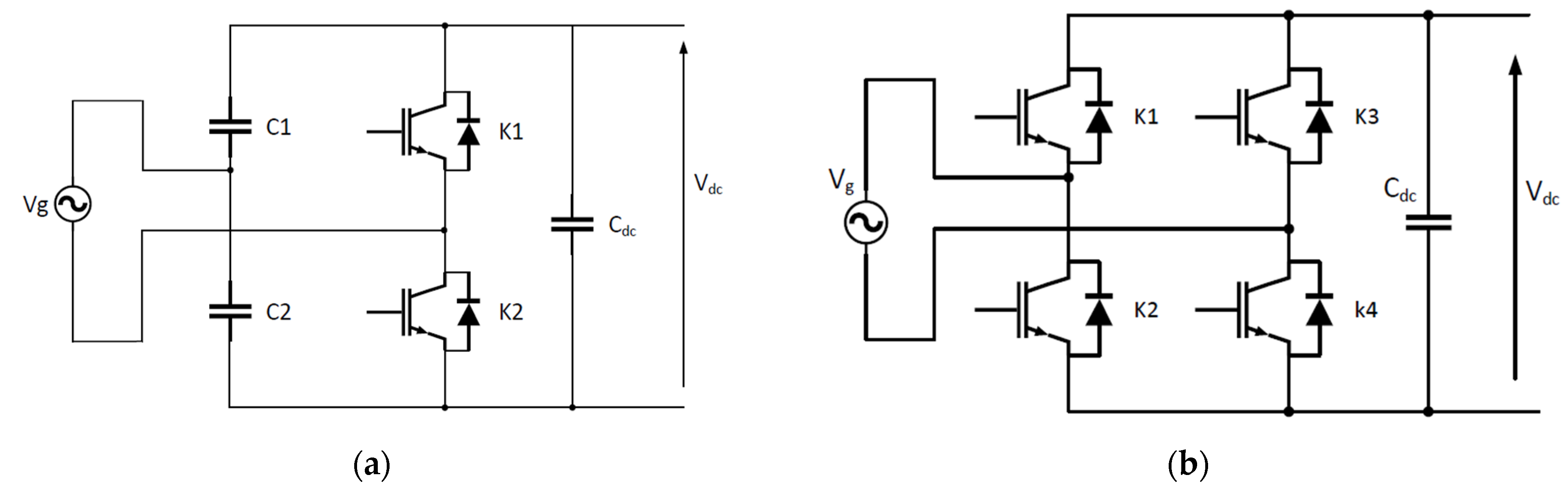
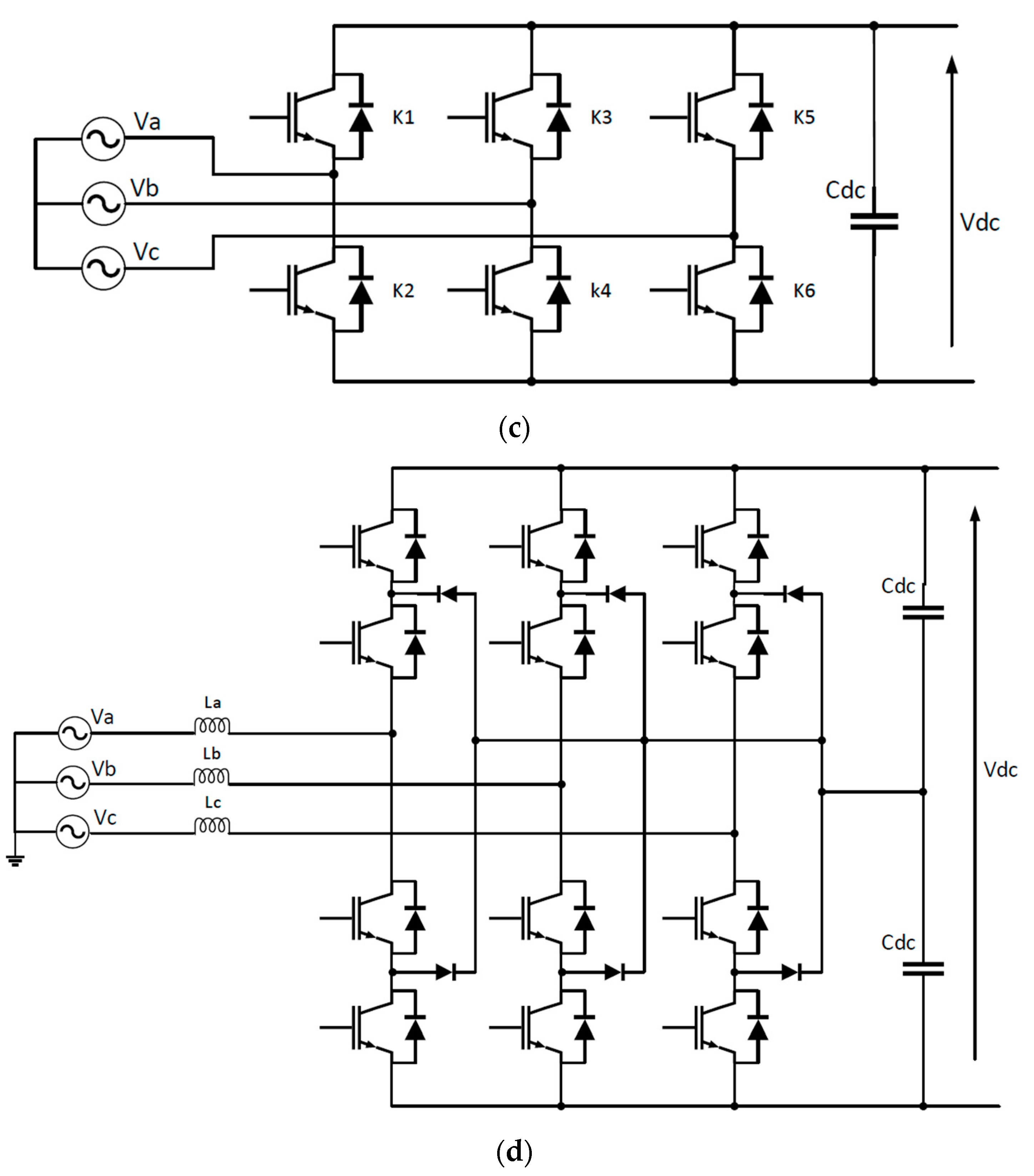
Figure 3. The electrical schematics of the commonly used bidirectional ac-dc power conversion stage in EV chargers: (a) Bidirectional half-bridge single-phase ac-dc power converter; (b) Bidirectional full-bridge single-phase ac-dc power converter; (c) Bidirectional three-phase ac-dc power converter; (d) Bidirectional three-level diode-clamped ac-dc power converter.
Figure 4 shows the most used dc-dc power circuitry for EV charging applications with V2X technology. However, Figure 4a illustrates a non-isolated bidirectional half-bridge dc-dc power converter, while Figure 4b presents its interleaved version. Figure 4c illustrates an isolated bidirectional dual-active bridge (DAB) dc-dc power converter, while Figure 4d shows its contactless version. It is a structure used for bidirectional inductive EV chargers; the left bridge is situated in the EV charging station, while the right one is embedded into the vehicle [25].
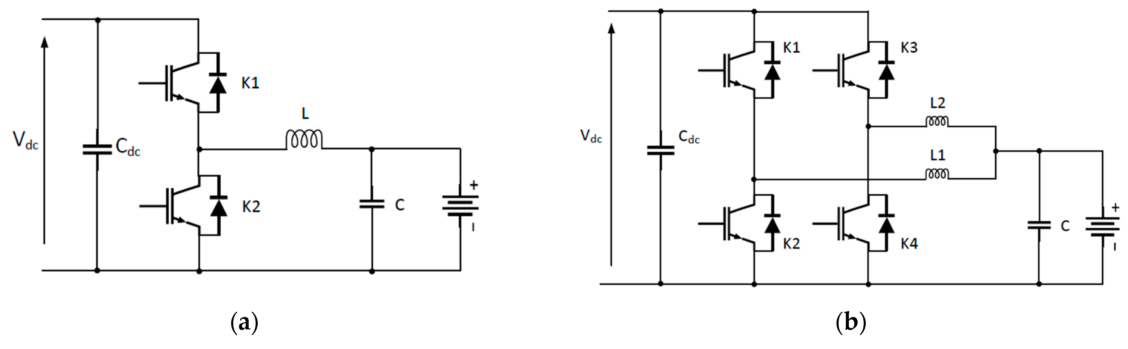
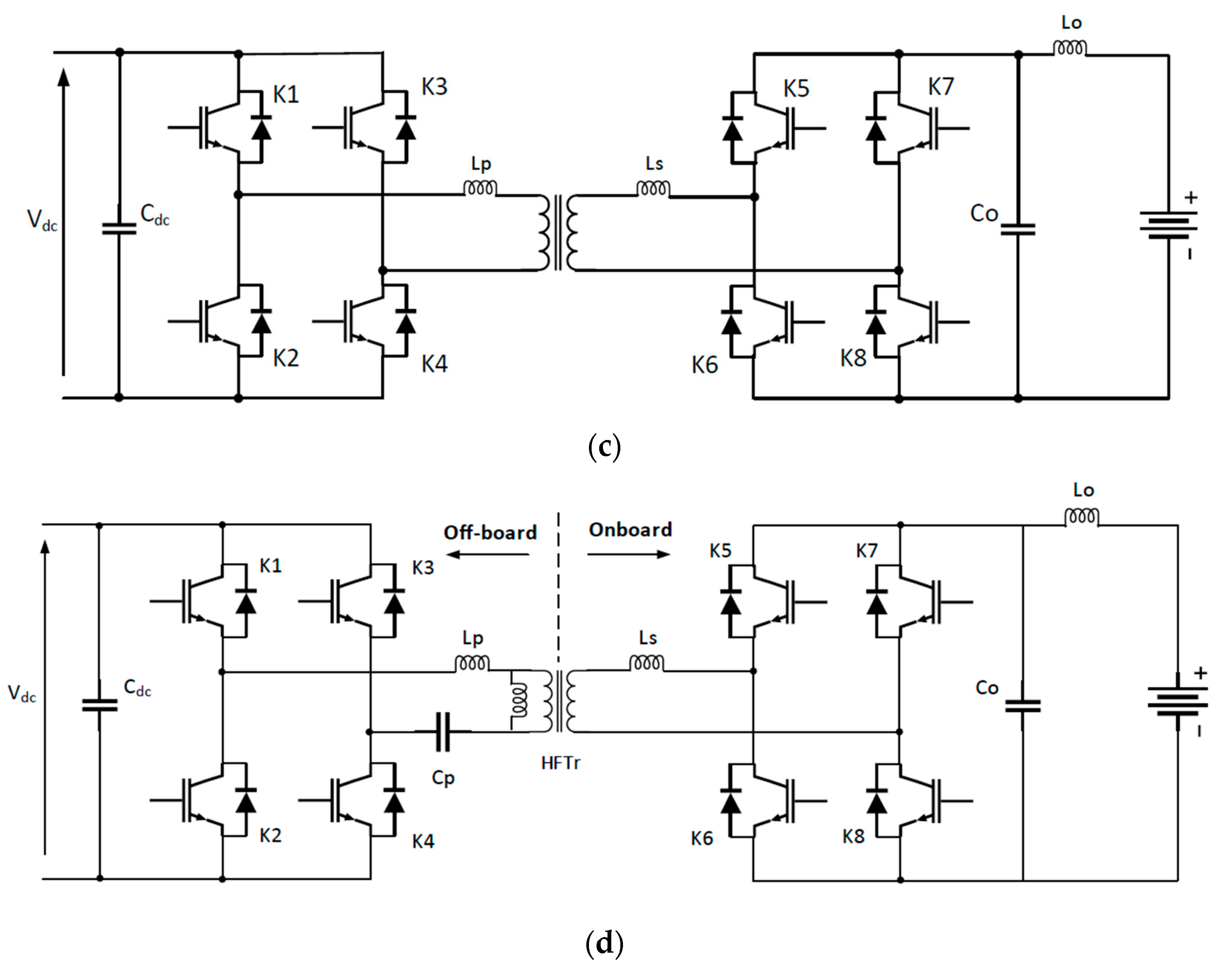
Figure 4. The electrical schematics of the most used dc-dc power conversion stage in EV chargers with V2X technology: (a) non-isolate bidirectional half-bridge dc-dc power converter; (b) Bidirectional interleave dc-dc power converter; (c) Isolated bidirectional dual-active bridge dc-dc power converter; (d) Inductive bidirectional dual-active bridge dc-dc power converter.
3. EV Charging Standards
3.1. SAE J1772 Standard
SAE J1772 is a standard published by SAE International that encompasses the general physical, electrical, functional, and quality criteria for EVs’ conductive charging process in North America [26]. This standard provides available conductive charging methods for EVs and electric vehicle supply equipment (EVSE), including the operational, functional, and dimensional requirements for the vehicle inlet and mating connector [27]. In addition, the SAE International terminology “Charging Levels” is utilized to classify the rated currents, voltages, and powers of the charging systems currently offered in North American markets [28][29]. Accordingly, the October 2017 revision of the SAE J1772 standard outlines four charging levels: AC Level 1, AC Level 2, DC Level 1, and DC Level 2 [30]. Table 2 lists and describes their charging configuration settings and ratings [31].
Table 2. Levels charging available in SAE J1772 (2017) configuration.
| Charging Level | Specifications |
|---|---|
| AC Level 1 |
|
| AC Level 2 |
|
| DC Level 1 |
|
| DC Level 2 |
|
1 BEV battery capacity is presumed to be 25 KWh, while that of PHEV is 5–15 KWh.
3.2. IEC 61851 Standard
In Europe and other countries, the IEC uses the terminology “Charging modes” to classify the methods of power distribution and protection installation, as well as the communication and management of the EV charging system [32]. Accordingly, as illustrated in Figure 5, the international standard IEC 61851-1 published in 2017 describes four distinct EV charging modes [33].
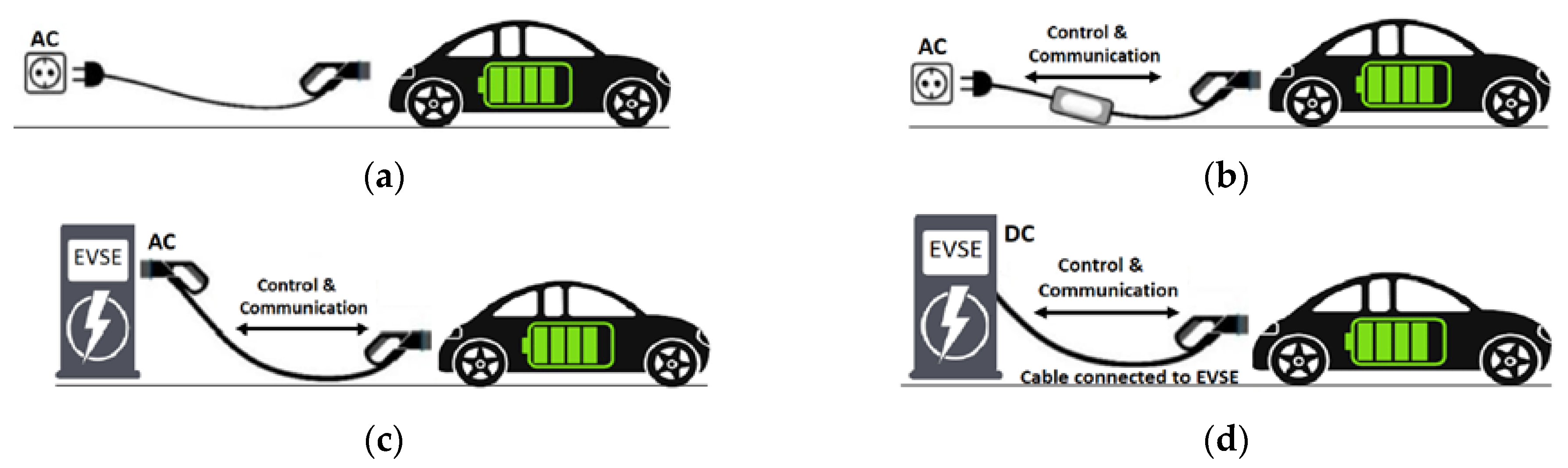
Figure 5. IEC 61851-1 Charging Modes: (a) Mode 1; (b) Mode 2; (c) Mode 3; (d) Mode 4.
3.3. China GB Standards
The China GB (Guo Biao) standards are mandatory or recommended. Mandatory standards, like other technical regulations in China, have legal force. They are regulated by legislation and authoritative rules to protect public health, private property, and safety. All standards that do not meet these criteria are deemed recommended (i.e., Quasi-Mandatory standards). GB standards are classified as Mandatory or Recommended based on their prefix code. GB is a mandatory standard, whereas GB/T is a recommended standard [34]. Table 3 summarizes the GB/T standards concerning the EV charging systems implemented in China.
Table 3. Overview of GB/T standards for EV charging system.
| Standard Code | GB Standard Title |
|---|---|
| GB/T 20234.1-2015 |
|
| GB/T 20234.2-2015 |
|
| GB/T 20234.3-2015 |
|
| GB/T 27930-2015 |
|
| GB/T 28569-2012 |
|
| GB/T 29317-2012 |
|
| GB/T 29318-2012 |
|
| GB/T 38775-2020 |
|
4. EV Charging Couplers
4.1. SAE J1772 Coupler
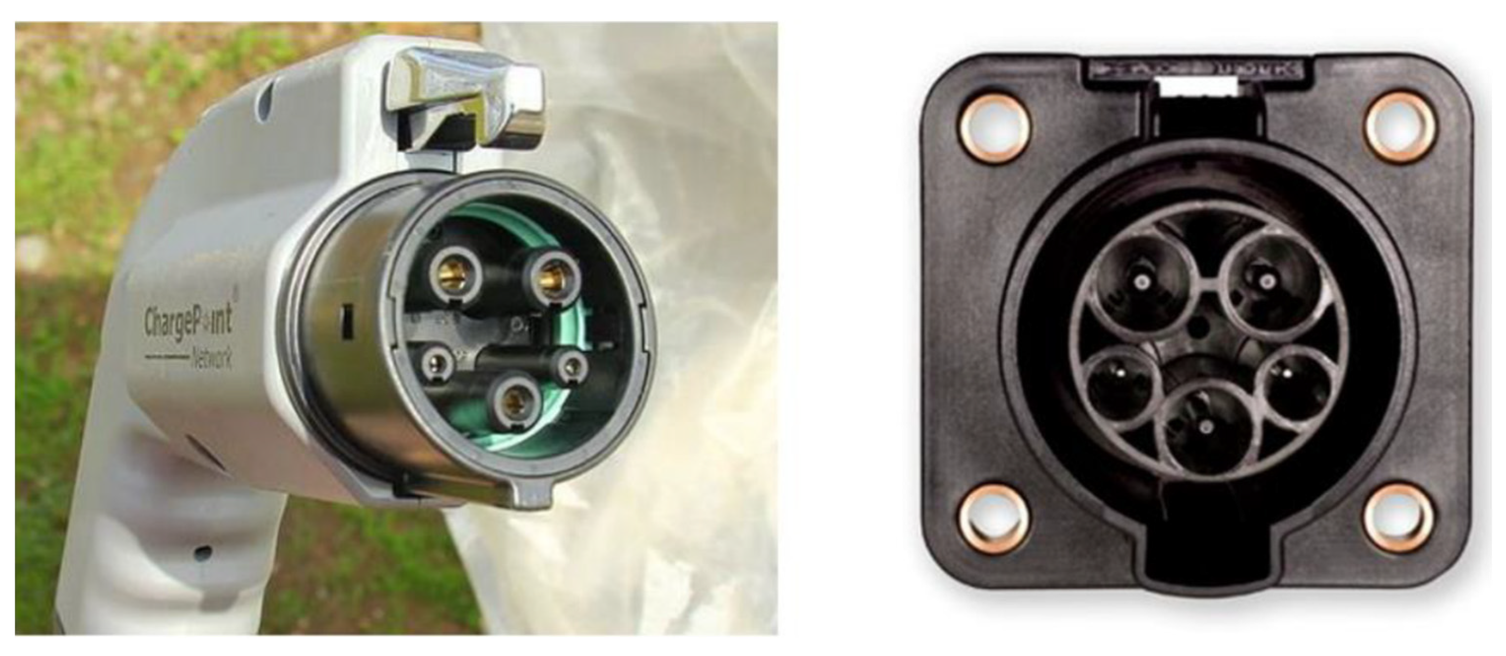
The Yazaki manufacturer produced the SAE J1772 coupler in 2009 with full respect to the SAE J1772-2009 standard. Its specifications were later stated to the IEC 62196-2 standard in May 2011 (i.e., IEC Type 1 coupler). It’s widely utilized for AC charging systems in the United States, Canada, and Japan. It accepts a single-phase AC power supply and can charge up to 19.2 kW (240 V @ 80 A). Figure 6 shows the EV J-plug and its corresponding EV Inlet [35].
Figure 6. The SAE J1772 EV charging coupler: EV Plug (Left) and Inlet (Right).
4.2. IEC Type 2 Coupler
The type 2 coupler had first been proposed by the German manufacturer “Mennekes” in 2009, and it is still commonly referred to as such (i.e., Mennekes Type 2). In January 2013, the European Commission designated it as an official charging coupler in the EU. Some other countries outside the EU, including Australia and New Zealand, are adopting the same coupler, while the Chinese standard GB/T 20234-2 outlines a similar but unique design. As is described in the IEC 62196-2 standard, this coupler was initially designed for AC charging systems. That means it can support a power-charging up to 7.4 kW (230 V @ 32 A) or 43 kW (400 V @ 63 A) from a single-phase or three-phase AC power supply, respectively [36][37][38].
4.3. CCS Combo Coupler
DC fast charging is also available in Europe, as it is in North America, where CCS Combo 2 is the standard utilized by almost all manufacturers except for Nissan and Mitsubishi [39]. It combines two DC-fast charging pins with the Type 2 connector in the same way that the CCS Combo 1 system (J1772 connector) does in the United States and Canada.
4.4. CHAdeMO Coupler
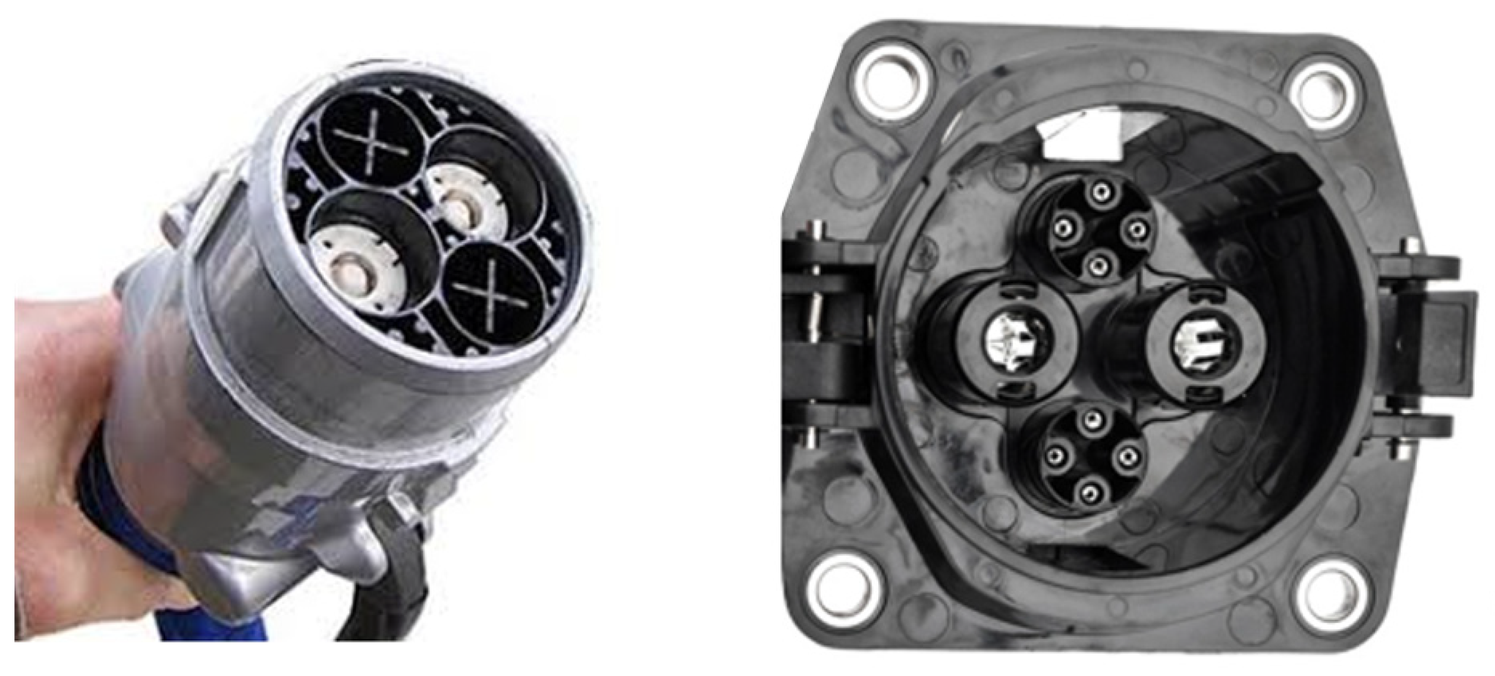
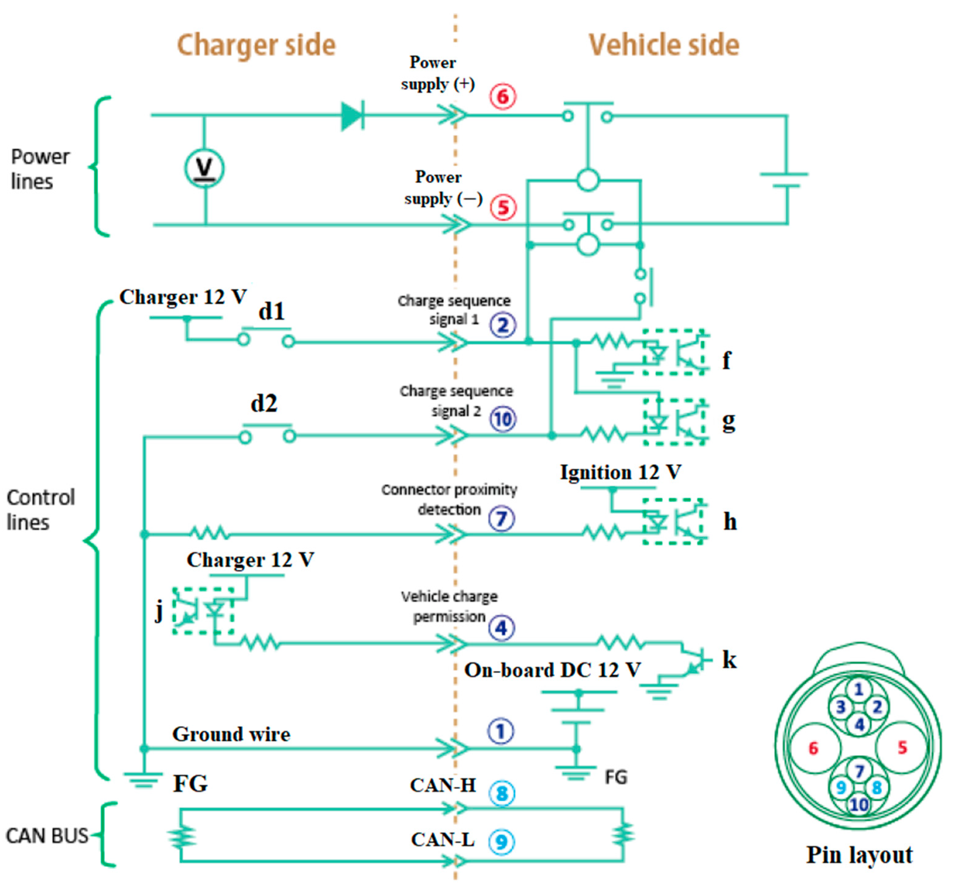
CHAdeMO is a DC fast-charging coupler for electric vehicles with a charging power ranging from 6 KW to 400 KW. Its coupler is shown in Figure 7, while Figure 8 illustrates its sequence circuit and pin layout [40]. There are ten (10) pins, and one of them is not connected (Pin #3). The sequence circuit establishes the exchanged parameters necessary during charging control. In addition, the EV and the DC fast-charging EVSE are equipped with terminating resistors for communications.
Figure 7. The CHAdeMO coupler: EV Plug (Left) and Inlet (Right).
Figure 8. CHAdeMO sequence circuit and pin layout.
4.5. GB/T Coupler
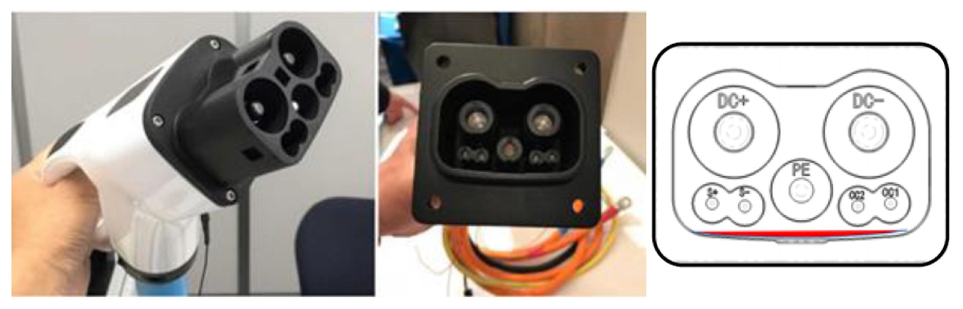
With the support of the governments of China and Japan, the CHAdeMO Organization and the China electricity council (CEC) have lately been working on a new international high-power DC charging standard that is backward compatible with existing CHAdeMO and GB/T standards. Figure 9 shows the new GB/T- CHAdeMO coupler prototype, which was revealed during the CHAdeMO general assembly with a charging power of up to 900 kW (1500 V @ 600 A) [41][42][43].
Figure 9. The ChaoJi coupler: EV Plug (Left), Inlet (Middle), and Inlet pinout (Right).
4.6. Tesla Coupler
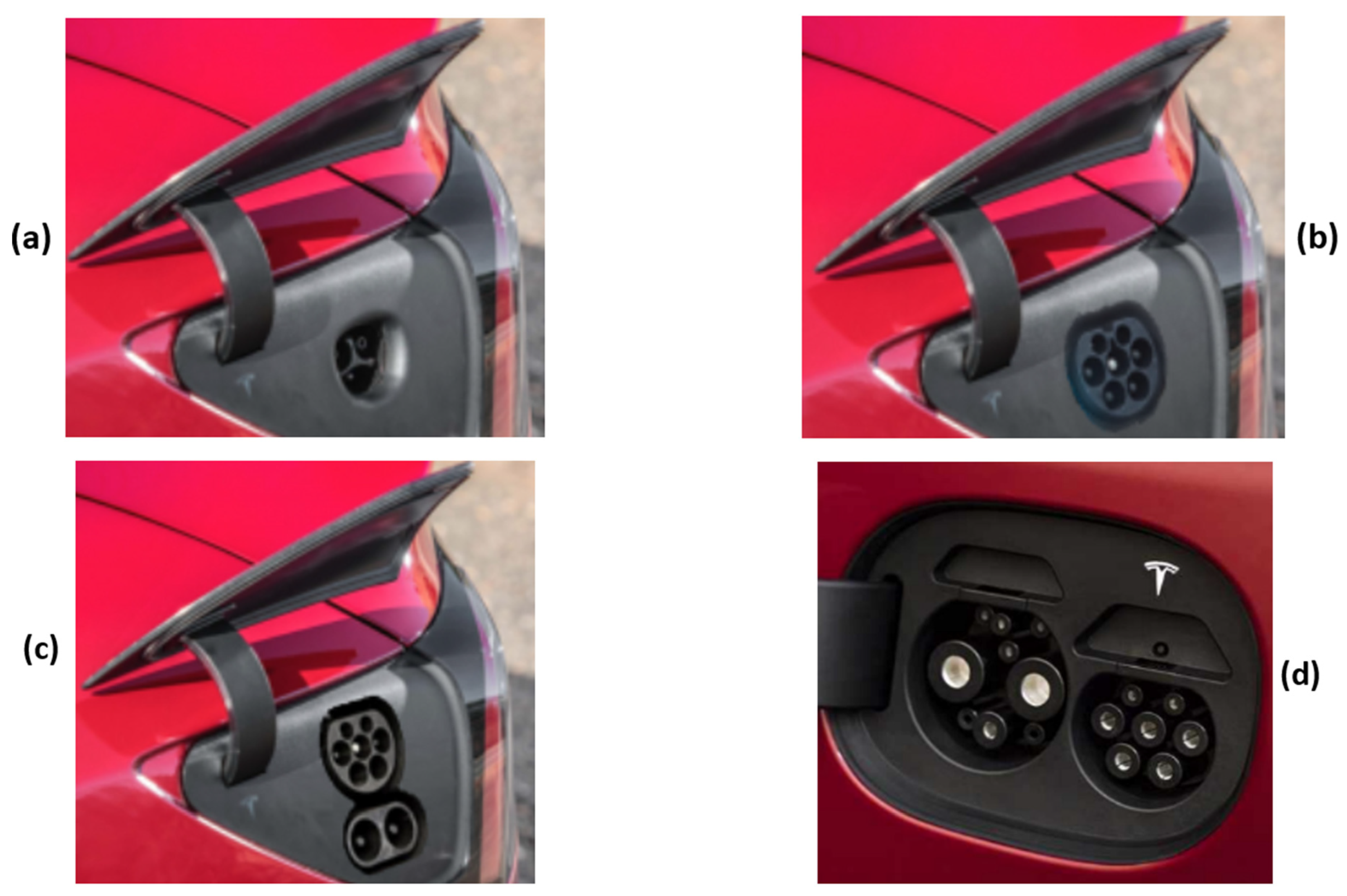
Founded in 2003, Tesla is a California brand specializing in EVs and energy. After its first EV, the Roadster 2008, the manufacturer has four models within its range: The Model S, the Model 3, the Model X, the Model Y, and the new Roadster 2020. The type of the Tesla EV inlet depends on the region in which the vehicle is sold. Thus, the US version is also sold in Canada, Mexico, Japan, and Taiwan and is equipped with the proprietary Tesla inlet, as shown in Figure 10. In contrast, Figure 10b illustrates that the Tesla vehicle sold in Europe is fitted with a Type 2 inlet or, more recently, a CCS Combo 2 inlet, as presented in Figure 10c. Finally, the Tesla vehicle in China is equipped with a dual inlet: AC GB/T and DC GB/T inlets, as shown in Figure 10d [44].
Figure 10. The Tesla EV inlet according to the region of sale: (a) US; (b) and (c) EU; (d) China.
5. EV Batteries
Commonly, an EV is equipped with two types of batteries: a high-voltage battery called a traction battery and a low-voltage battery. The first is the principal energy source that supplies the electric traction motor via a three-phase power inverter. It is generally Lithium-ion based and can be charged using the ac-current through an on-board charger or directly using the dc-current provided by the dc fast-charging stations. However, a third charging technique called battery swapping makes it possible to exchange the drained battery with a charged one [45][46][47]. The second is a 12 V lead-acid battery that supplies the vehicle’s auxiliary loads [48]. It is charged from the high-voltage battery through a dc-dc converter [49].
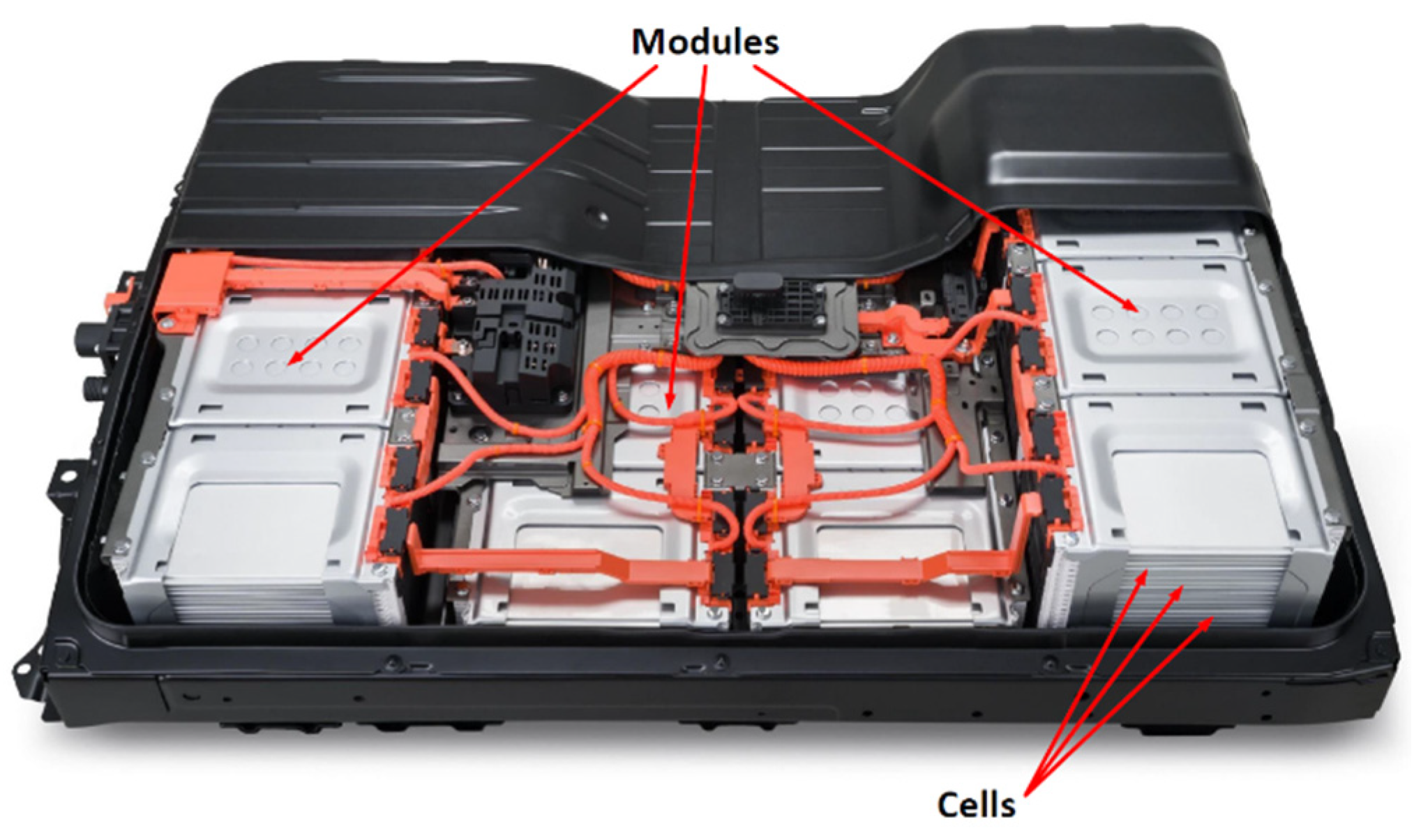
The high-voltage battery is made up of several individual cells that are grouped into modules. These are added to each other to form the final traction battery, as shown in Figure 11. The design of the battery cells varies depending on the vehicle manufacturer. In this case, the deciding factors are, e.g., energy density, heat dissipation, manufacturing cost, weight, modular adaptability, or mechanical stability. An anode (the negative pole), a cathode (the positive pole), and an electrolyte make up a battery cell [50]. The electrolyte is a conductive (liquid or solid) element that allows current flow between poles. Battery operation is based on using a pair of metals capable of exchanging electrons. Based on these metals, EV batteries will be classified in the next section.
Figure 11. The high-voltage battery components.
References
- Kisacikoglu, M.C. Vehicle-to-Grid (V2G) Reactive Power Operation Analysis of the EV/PHEV Bidirectional Battery Charger. Ph.D. Thesis, University of Tennessee, Knoxville, TN, USA, 2013.
- Xiao, X.; Molin, H.; Kourtza, P.; Collin, A.; Harrison, G.; Djokic, S.; Meyer, J.; Müller, S.; Möller, F. Component-Based Modelling of EV Battery Chargers. In Proceedings of the 2015 IEEE Eindhoven PowerTech, Eindhoven, The Netherlands, 29 June–2 July 2015; pp. 1–6.
- Ronanki, D.; Kelkar, A.; Williamson, S.S. Extreme Fast Charging Technology—Prospects to Enhance Sustainable Electric Transportation. Energies 2019, 12, 3721.
- Kumar, P.; Nikolovski, S.; Dong, Z.Y. (Eds.) Internet of Energy Handbook, 1st ed.; CRC Press: Boca Raton, FL, USA, 2021; ISBN 978-0-367-49964-8.
- Rachid, A.; Fadil, H.E.; Rachid, K.; Lassioui, A.; Idrissi, Z.E. H-Infinity Control of Bidirectional Dc-Dc Power Converter for V2G BEV Charger. In Proceedings of the 2020 International Symposium on Advanced Electrical and Communication Technologies (ISAECT), Marrakech, Morocco, 25–27 November 2020; pp. 1–6.
- Sousa, T.J.C.; Pedrosa, D.; Monteiro, V.; Afonso, J.L. A Review on Integrated Battery Chargers for Electric Vehicles. Energies 2022, 15, 2756.
- Lebrouhi, B.E.; Khattari, Y.; Lamrani, B.; Maaroufi, M.; Zeraouli, Y.; Kousksou, T. Key Challenges for a Large-Scale Development of Battery Electric Vehicles: A Comprehensive Review. J. Energy Storage 2021, 44, 103273.
- Rubino, L.; Capasso, C.; Veneri, O. Review on Plug-in Electric Vehicle Charging Architectures Integrated with Distributed Energy Sources for Sustainable Mobility. Appl. Energy 2017, 207, 438–464.
- Mohamed, A.A.S.; Shaier, A.A.; Metwally, H.; Selem, S.I. A Comprehensive Overview of Inductive Pad in Electric Vehicles Stationary Charging. Appl. Energy 2020, 262, 114584.
- Lassioui, A.; Fadil, H.E.; Rachid, A.; El-Idrissi, Z.; Bouanou, T.; Belhaj, F.Z.; Giri, F. Modelling and Sliding Mode Control of a Wireless Power Transfer System for BEV Charger. Int. J. Model. Identif. Control 2020, 34, 171–186.
- Amjad, M.; Farooq-i-Azam, M.; Ni, Q.; Dong, M.; Ansari, E.A. Wireless Charging Systems for Electric Vehicles. Renew. Sustain. Energy Rev. 2022, 167, 112730.
- Lassioui, A.; Fadil, H.E.; Rachid, A.; Belhaj, F.Z.; Tarkany, O.; Bajit, A. Characteristics Analysis of Wireless Power Transfer System for Electric Vehicle Charging Applications. In Proceedings of the 2018 International Symposium on Advanced Electrical and Communication Technologies (ISAECT), Rabat, Morocco, 21–23 November 2018; pp. 1–6.
- Lassioui, A.; El Fadil, H.; Belhaj, F.Z.; Rachid, A. Battery Charger for Electric Vehicles Based ICPT and CPT—A State of the Art. In Proceedings of the 2018 Renewable Energies, Power Systems & Green Inclusive Economy (REPS-GIE), Casablanca, Morocco, 23–24 April 2018; pp. 1–6.
- Monteiro, V.; Afonso, J.A.; Sousa, T.J.C.; Cardoso, L.L.; Pinto, J.G.; Afonso, J.L. Vehicle Electrification: Technologies, Challenges, and a Global Perspective for Smart Grids. In Innovation in Energy Systems; Ustun, T.S., Ed.; IntechOpen: Rijeka, Croatia, 2019.
- Mutarraf, M.U.; Guan, Y.; Xu, L.; Su, C.-L.; Vasquez, J.C.; Guerrero, J.M. Electric Cars, Ships, and Their Charging Infrastructure—A Comprehensive Review. Sustain. Energy Technol. Assess. 2022, 52, 102177.
- Ahmed, I.; Adil, H.M.M.; Ahmed, S.; Ahmad, I.; Rehman, Z. Robust Nonlinear Control of Battery Electric Vehicle Charger in Grid to Vehicle and Vehicle to Grid Applications. J. Energy Storage 2022, 52, 104813.
- Rachid, A.; EL Fadil, H.; Lassioui, A.; Giri, F. Advanced Control of Bidirectional Three-Phase BEV Charger with V2X Technology. Int. J. Model. Identif. Control 2019, 33, 344–357.
- Rachid, A.; El Fadil, H.; Giri, F.; Lassioui, A. Nonlinear Output Feedback Control of V2G Single-Phase on-Board BEV Charger. Asian J. Control 2020, 22, 1848–1859.
- Rachid, A.; Fadil, H.E.; Koundi, M.; Idrissi, Z.E.; Tahri, A.; Giri, F.; Guerrero, J.M. PQ Theory-Based Control of Single-Stage V2G Three-Phase BEV Charger for High-Voltage Battery. IFAC-Pap. 2019, 52, 73–78.
- Rachid, A.; Fadil, H.E.; Giri, F. Dual Stage CC-CV Charge Method for Controlling DC-DC Power Converter in BEV Charger. In Proceedings of the 2018 19th IEEE Mediterranean Electrotechnical Conference (MELECON), Marrakech, Morocco, 2–7 May 2018; pp. 74–79.
- Rachid, K.; EL Fadil, H.; Rachid, A.; Bouanou, T.; Gaouzi, K.; Belhaj, F.Z. Nonlinear Output Feedback Control of Bidirectional Dc-Dc Power Converter for V2X BEV Charger: Theoretical Analysis and Experimental Results. In Proceedings of the International Symposium on Advanced Electrical and Communication Technologies (ISAECT2020), Kenitra, Morocco, 25–27 November 2020; pp. 1–6.
- Ashfaq, M.; Butt, O.; Selvaraj, J.; Rahim, N. Assessment of Electric Vehicle Charging Infrastructure and Its Impact on the Electric Grid: A Review. Int. J. Green Energy 2021, 18, 657–686.
- Sayed, K.; Gabbar, H. Electric Vehicle to Power Grid Integration Using Three-Level AC/DC Converter and PI-Fuzzy Controller. Energies 2016, 9, 532.
- Tahir, M. Electric Vehicles and Vehicle-to-Grid Technology. Master’s Thesis, The Arctic University of Norway, Tromsø, Norway, 2017.
- Grbović, P. Interface DC–DC Converters. In Ultra-Capacitors in Power Conversion Systems; John Wiley & Sons, Ltd.: Hoboken, NJ, USA, 2013; pp. 216–315. ISBN 978-1-118-69363-6.
- Zhang, T. Smart Electric Vehicle Charging: Mitigating Supply-Demand Disparity Through User Incentives—ProQuest. Ph.D. Thesis, University of California, Los Angeles, CA, USA, 2018.
- Ayob, A.; Mohd Faizal Wan Mahmood, W.; Mohamed, A.; Zamri Che Wanik, M.; Mohd Siam, M.; Sulaiman, S.; Hanifah Azit, A.; Azrin Mohamed Ali, M. Review on Electric Vehicle, Battery Charger, Charging Station and Standards. RJASET 2014, 7, 364–373.
- SAE International J1772_201001: SAE Electric Vehicle and Plug in Hybrid Electric Vehicle Conductive Charge Coupler—SAE International. Available online: https://www.sae.org/standards/content/j1772_201001/ (accessed on 26 July 2022).
- Paulraj, P. Charging Basics 102: Electric Vehicle Charging Levels, Modes and Types Explained | North America vs. Europe Charging Cables and Plug Types. E-Mobility Simplified|Basics of Electric Vehicles and Charging 2019. Available online: https://www.emobilitysimplified.com/2019/10/ev-charging-levels-modes-types-explained.html (accessed on 27 July 2022).
- SAE International J1772_201710: SAE Electric Vehicle and Plug in Hybrid Electric Vehicle Conductive Charge Coupler—SAE International. Available online: https://www.sae.org/standards/content/j1772_201710/ (accessed on 26 July 2022).
- Wikipedia, The Free Encyclopedia. Wikipedia contributors SAE J1772. 2020. Available online: https://en.wikipedia.org/w/index.php?title=SAE_J1772&oldid=965111434 (accessed on 26 July 2022).
- Hanauer, D. Mode 2 Charging—Testing and Certification for International Market Access. World Electr. Veh. J. 2018, 9, 26.
- International Electrotechnical Commission IEC 61851-1:2017: Electric Vehicle Conductive Charging System—Part 1: General Requirements 2017. Available online: https://webstore.iec.ch/publication/33644 (accessed on 26 July 2022).
- GB China National Standards. Available online: http://www.gbstandards.org/ (accessed on 28 July 2022).
- Hicks, M. English: SAE J1772 Plug (Cropped from the Original Photo). 2012. Available online: https://commons.wikimedia.org/wiki/File:SAE_J1772_7058855567.jpg (accessed on 26 July 2022).
- Hackaday. Lewin Day EV Charging Connectors Come In Many Shapes And Sizes. 2022. Available online: https://hackaday.com/2022/04/28/ev-charging-connectors-come-in-many-shapes-and-sizes/ (accessed on 28 July 2022).
- Recharge électrique. Tom Définition: C’est quoi une prise de recharge Type 2? 2020. Available online: https://www.recharge-electrique.com/definition-prise-recharge-electrique-type-2/ (accessed on 26 July 2022).
- Rivera, S.; Kouro, S.; Vazquez, S.; Goetz, S.M.; Lizana, R.; Romero-Cadaval, E. Electric Vehicle Charging Infrastructure: From Grid to Battery. IEEE Ind. Electron. Mag. 2021, 15, 37–51.
- Enel X Way The Different EV Charging Connector Types. Available online: https://evcharging.enelx.com/resources/blog/552-ev-charging-connector-types (accessed on 26 July 2022).
- Aitor Ubierna (ITE). Samuel Sánchez (ITE) D8.2 WiseGRID FastV2G and Other Innovative Optimized Storage Solutions 2018. Available online: https://cdn.nimbu.io/s/76bdjzc/channelentries/8qd2nl6/files/D8.2_WiseGRID_FastV2G_Design.pdf?aopz8sn (accessed on 26 July 2022).
- Dong, L.Y.; Yoshida, M.D. ChaoJi Standard 2020. Available online: https://www.chademo.com/wp2016/wp-content/uploads/ChaoJi202006/ChaoJi_Presenataion_EN.pdf (accessed on 18 July 2022).
- Kane, M. Here Is the Prototype for the New GB/T—CHAdeMO Plug and Inlet. Available online: https://insideevs.com/news/356958/prototype-new-gbt-chademo-plug-inlet/ (accessed on 26 July 2022).
- Berman, B. CHAdeMO 3.0 to Harmonize Global EV Quick Charging Standards. Available online: https://www.sae.org/site/news/2020/05/chademo-3.0-to-harmonize-global-ev-quick-charging-standards (accessed on 29 July 2022).
- David Herron Types of Electric Car Charging Connectors, and Compatibility: A Field Guide to Electric Vehicle Service Equipment. Available online: https://greentransportation.info/ev-charging/range-confidence/chap4-charging/4-evse-field-guide.html (accessed on 26 July 2022).
- Ahmad, A.; Khan, Z.A.; Saad Alam, M.; Khateeb, S. A Review of the Electric Vehicle Charging Techniques, Standards, Progression and Evolution of EV Technologies in Germany. Smart Sci. 2018, 6, 36–53.
- Adegbohun, F.; von Jouanne, A.; Lee, K.Y. Autonomous Battery Swapping System and Methodologies of Electric Vehicles. Energies 2019, 12, 667.
- Aleksander Chudy Battery Swapping Stations for Electric Vehicles. Inform. Autom. Pomiary W Gospod. I Ochr. Środowiska 2021, 11, 36–39.
- Pistoia, G.; Liaw, B. (Eds.) Behaviour of Lithium-Ion Batteries in Electric Vehicles; Green Energy and Technology; Springer International Publishing: Cham, Switzwerland, 2018; ISBN 978-3-319-69949-3.
- Sayed, K. Zero-Voltage Soft-Switching DC–DC Converter-Based Charger for LV Battery in Hybrid Electric Vehicles. IET Power Electron. 2019, 12, 3389–3396.
- Ghalkhani, M.; Habibi, S. Review of the Li-Ion Battery, Thermal Management, and AI-Based Battery Management System for EV Application. Energies 2023, 16, 185.
More
Information
Contributors
MDPI registered users' name will be linked to their SciProfiles pages. To register with us, please refer to https://encyclopedia.pub/register
:
View Times:
2.8K
Revisions:
3 times
(View History)
Update Date:
27 Feb 2023
Table of Contents


Notice
You are not a member of the advisory board for this topic. If you want to update advisory board member profile, please contact office@encyclopedia.pub.
OK
Confirm
Only members of the Encyclopedia advisory board for this topic are allowed to note entries. Would you like to become an advisory board member of the Encyclopedia?
Yes
No
${ textCharacter }/${ maxCharacter }
Submit
Cancel
Back
Comments
${ item }
|
${ item.createdUser.fullName }
${ item.createdAt }
${ item.vote }
${ item.reply }
Delete
${ reply.createdUser.fullName }
${ reply.createdAt }
${ reply.vote }
Delete
There is no reply to this comment~
${ item.replyTextCharacter }/${ item.replyMaxCharacter }
Submit
Cancel
More
No more~
There is no comment~
${ textCharacter }/${ maxCharacter }
Submit
Cancel
${ selectedItem.replyTextCharacter }/${ selectedItem.replyMaxCharacter }
Submit
Cancel
Confirm
Are you sure to Delete?
Yes
No