The high-voltage battery is a crucial element for electric vehicles (EVs) traction systems. It is the primary energy source that must be regularly recharged to reach the autonomy declared by the manufacturer. Therefore, an EV charging system is required to ensure the battery charging process.
- EV charging system
- EV charger standards
- bidirectional EV charger topologies
12. Classification and Topologies of EV Charger
1.1. EV Chargers Classification
2.1. EV Chargers Classification
| EV Chargers | Description | |
|---|---|---|
| Offboard chargers | All the components required for the EV charging and discharging process are inside the public EV charging station [3][4]. | All the components required for the EV charging and discharging process are inside the public EV charging station [32,33]. |
| On-board chargers | Some components required for the battery-charging process are embedded inside the EV. |


3. EV Charging Standards
3.1. SAE J1772 Standard
| Charging Level | Specifications | ||||
|---|---|---|---|---|---|
| AC Level 1 |
| ||||
| AC Level 2 |
| ||||
| Unidirectional chargers | The electrical energy transfer is one-way from the EV charging station to the EV battery. Therefore, only the G2V operation mode is possible. | ||||
| Bidirectional chargers | The electrical energy flow can be from or to the EV battery. Thus, V2X technology can be ensured by this type of charger [5]. | The electrical energy flow can be from or to the EV battery. Thus, V2X technology can be ensured by this type of charger [34]. | |||
| Dedicated chargers | All equipment making up the charger is exclusively utilized to guarantee the EV charging or discharging process. | ||||
| Integrated chargers | When the EV is linked to the electricity network, the traction system constituents (Motors, inverters, etc.) are used to guarantee the EV charging or discharging process [6]. | When the EV is linked to the electricity network, the traction system constituents (Motors, inverters, etc.) are used to guarantee the EV charging or discharging process [35]. | |||
| Conductive chargers | A dedicated electrical cable links the EV to the electricity network. | ||||
| Wireless Power Transfer Chargers [7] | Wireless Power Transfer Chargers [36] |
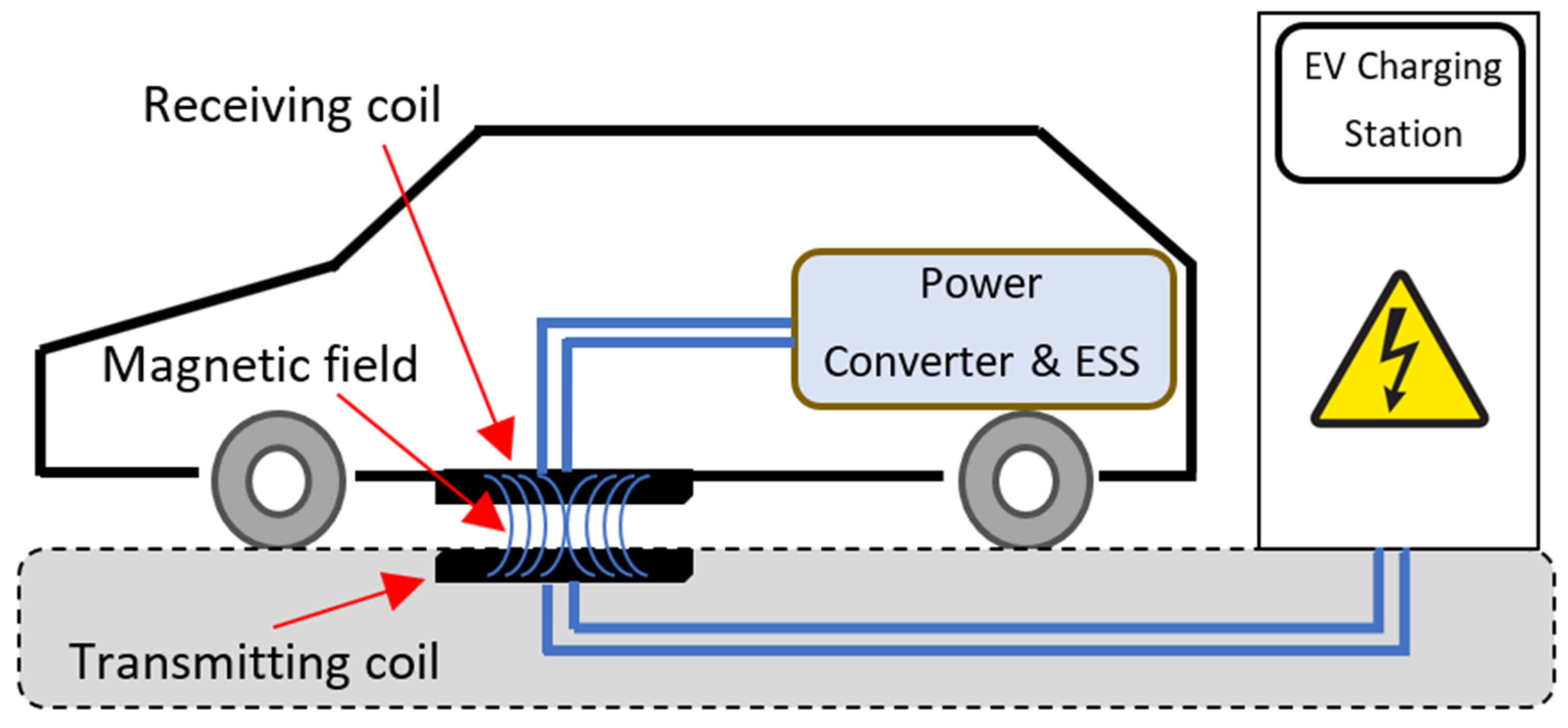
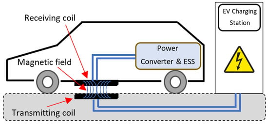
It is a contactless charging technology. No cables are utilized between the EV and the electricity network [8]. Instead, the electrical energy transfer is based on electromagnetic induction [9]. | It is a contactless charging technology. No cables are utilized between the EV and the electricity network [37]. Instead, the electrical energy transfer is based on electromagnetic induction [38]. | Figure 6 illustrates the concept of this EV charger type [10]. Compared with conductive chargers, these inductive chargers present various advantages [11]. Especially the convenience for the user and the intrinsic galvanic insulation, while the cost and the need for custom hardware inside the EV are the main drawbacks [12][13]. | illustrates the concept of this EV charger type [39]. Compared with conductive chargers, these inductive chargers present various advantages [40]. Especially the convenience for the user and the intrinsic galvanic insulation, while the cost and the need for custom hardware inside the EV are the main drawbacks [41,42]. |
| Single-stage & Dual-stage chargers |
The first one consists of a single power conversion: only one ac-dc or one dc-dc power converter. The second one involves double power stages: ac-dc and dc-dc power conversions. |
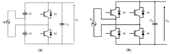
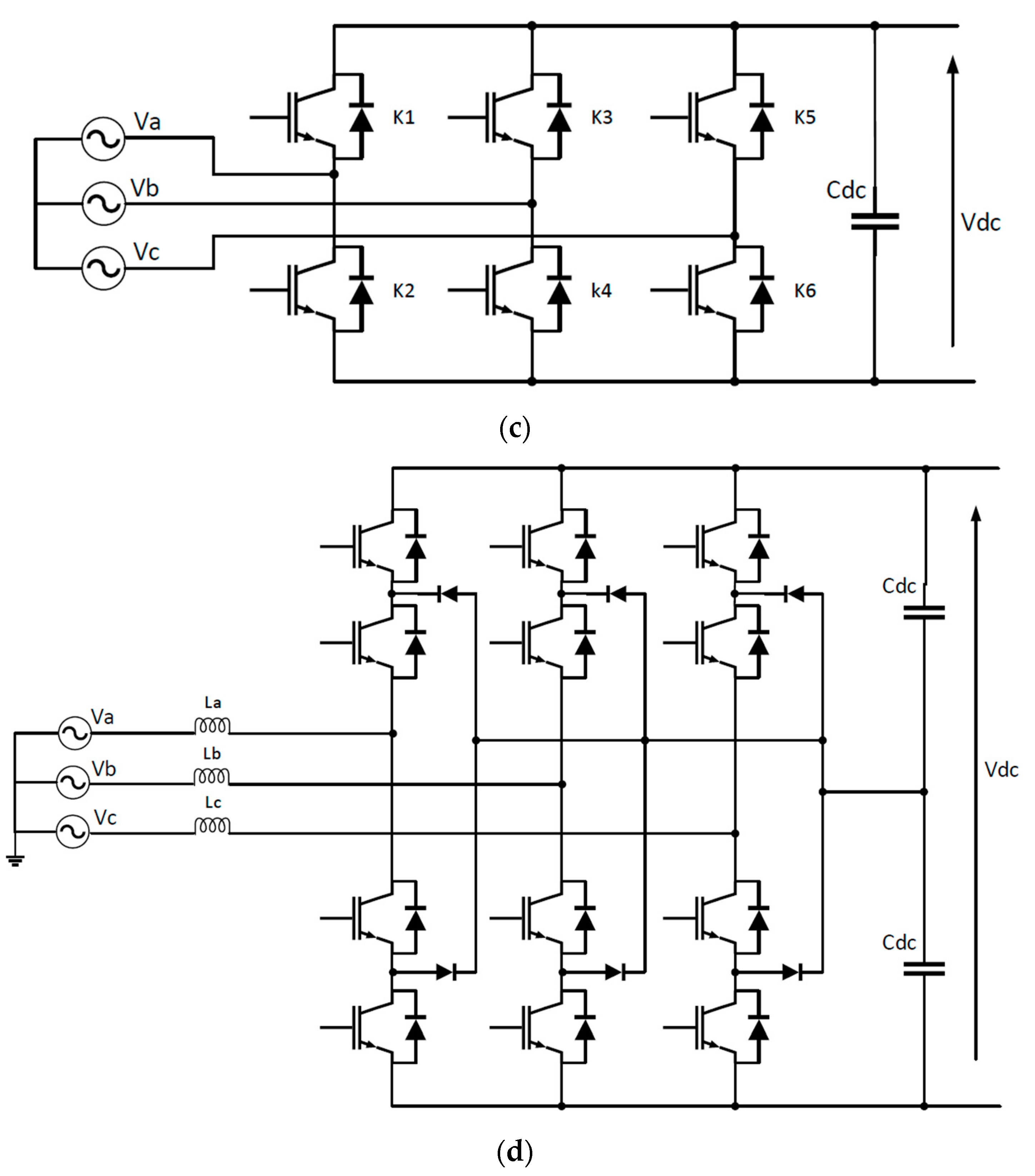
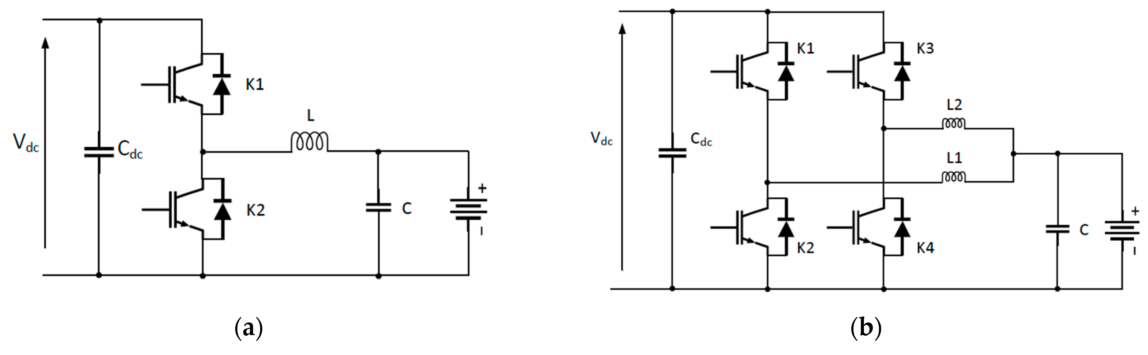
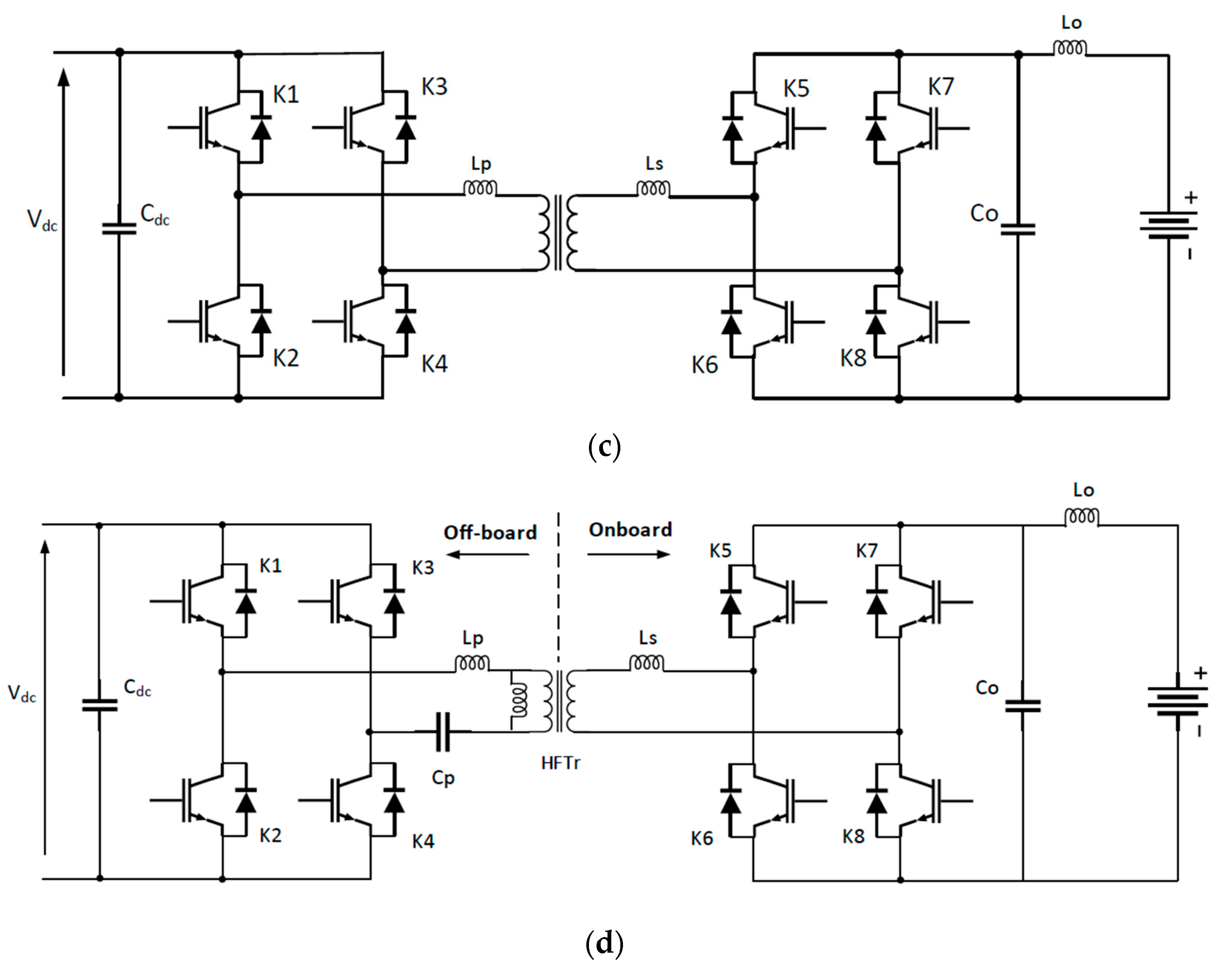
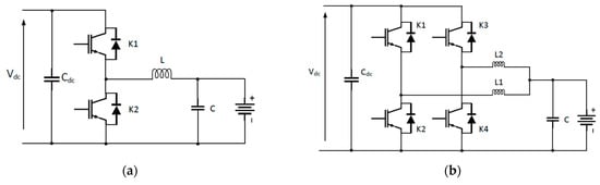
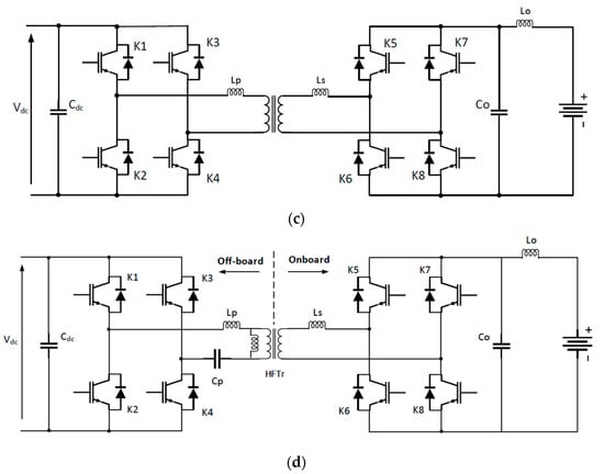
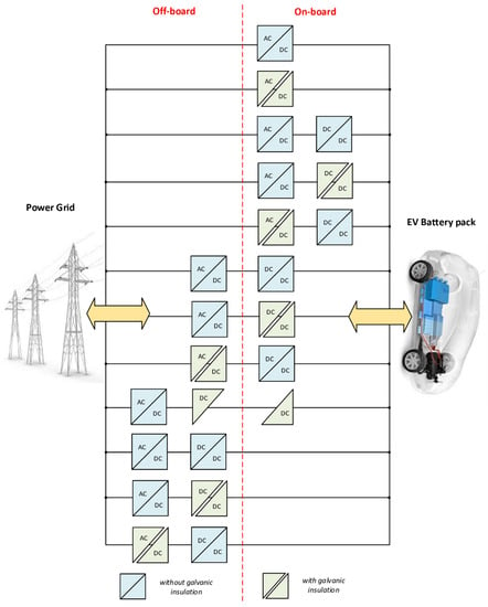
1.2. EV Charger Topologies
2.2. EV Charger Topologies
| ||
| ||
|
3.2. IEC 61851 Standard
In Europe and other countries, the IEC uses the terminology “Charging modes” to classify the methods of power distribution and protection installation, as well as the communication and management of the EV charging system [32][77]. Accordingly, as illustrated in Figure 510, the international standard IEC 61851-1 published in 2017 describes four distinct EV charging modes [33][78].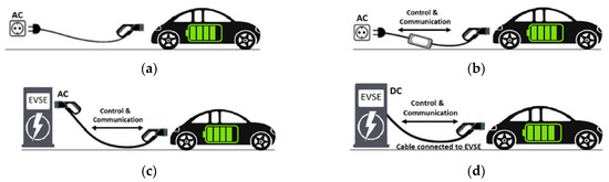
3.3. China GB Standards
3.3. China GB Standards
| Standard Code | GB Standard Title | ||||
|---|---|---|---|---|---|
| GB/T 20234.1-2015 |
| ||||
| GB/T 20234.2-2015 |
| ||||
| DC Level 1 |
| ||||
| GB/T 20234.3-2015 | |||||
| DC Level 2 |
| |||
| GB/T 27930-2015 |
|
| |||
| GB/T 28569-2012 |
| ||||
| GB/T 29317-2012 |
| ||||
| GB/T 29318-2012 |
| ||||
| GB/T 38775-2020 |
|
4. EV Charging Couplers
4.1. SAE J1772 Coupler
The Yazaki manufacturer produced the SAE J1772 coupler in 2009 with full respect to the SAE J1772-2009 standard. Its specifications were later stated to the IEC 62196-2 standard in May 2011 (i.e., IEC Type 1 coupler). It’s widely utilized for AC charging systems in the United States, Canada, and Japan. It accepts a single-phase AC power supply and can charge up to 19.2 kW (240 V @ 80 A). 11 shows the EV J-plug and its corresponding EV Inlet [86].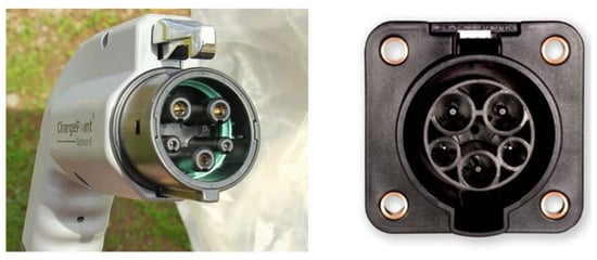
4.2. IEC Type 2 Coupler
4.3. CCS Combo Coupler
4.3. CCS Combo Coupler
DC fast charging is also available in Europe, as it is in North America, where CCS Combo 2 is the standard utilized by almost all manufacturers except for Nissan and Mitsubishi [39][85]. It combines two DC-fast charging pins with the Type 2 connector in the same way that the CCS Combo 1 system (J1772 connector) does in the United States and Canada.4.4. CHAdeMO Coupler
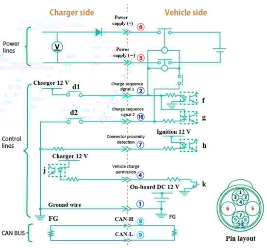
CHAdeMO is a DC fast-charging coupler for electric vehicles with a charging power ranging from 6 KW to 400 KW. Its coupler is shown in Figure 17, while Figure 18 illustrates its sequence circuit and pin layout [40][96]. There are ten (10) pins, and one of them is not connected (Pin #3). The sequence circuit establishes the exchanged parameters necessary during charging control. In addition, the EV and the DC fast-charging EVSE are equipped with terminating resistors for communications.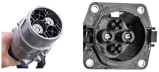
4.5. GB/T Coupler
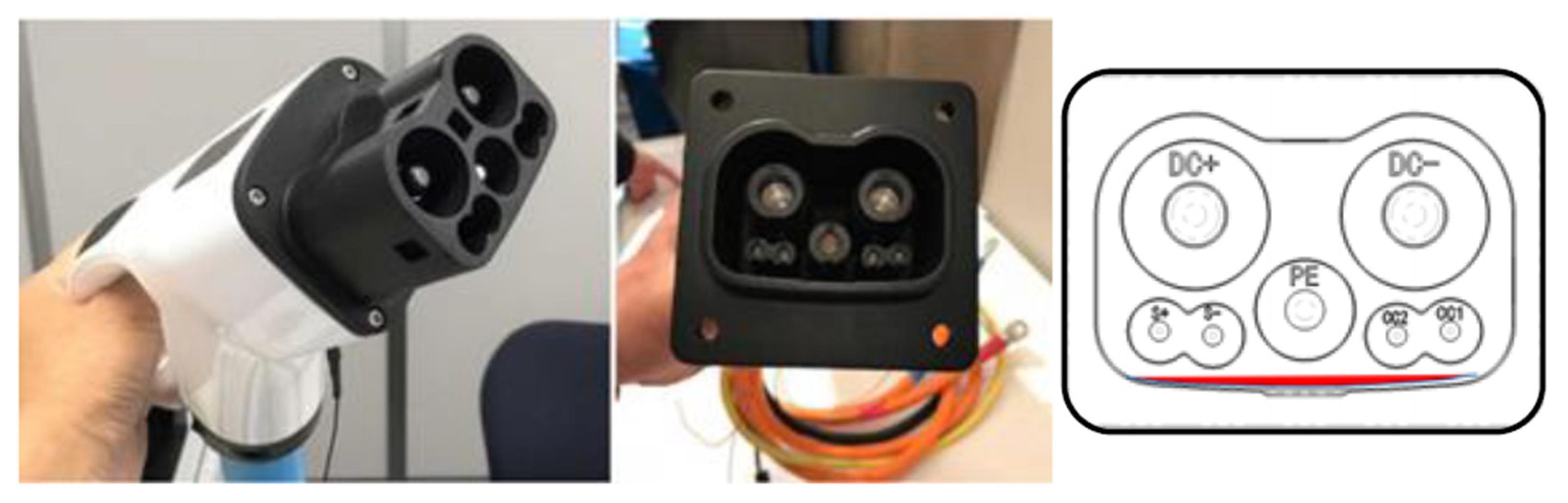
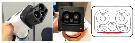
With the support of the governments of China and Japan, the CHAdeMO Organization and the China electricity council (CEC) have lately been working on a new international high-power DC charging standard that is backward compatible with existing CHAdeMO and GB/T standards. Figure 925 shows the new GB/T- CHAdeMO coupler prototype, which was revealed during the CHAdeMO general assembly with a charging power of up to 900 kW (1500 V @ 600 A) [41][42][43][101,108,109].
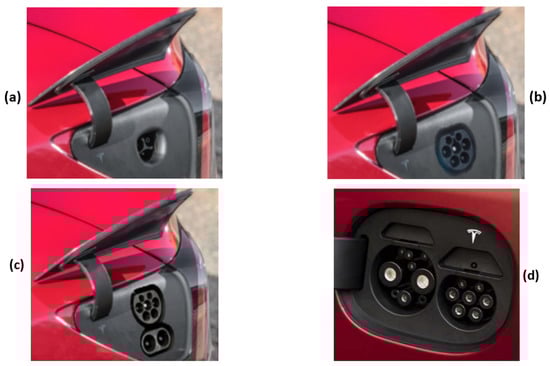
4.6. Tesla Coupler
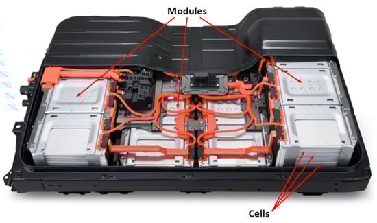
5. EV Batteries