| Version | Summary | Created by | Modification | Content Size | Created at | Operation |
|---|---|---|---|---|---|---|
| 1 | Miguel V. Andrés | -- | 1778 | 2023-02-16 12:36:11 | | | |
| 2 | Lindsay Dong | + 120 word(s) | 1898 | 2023-02-17 03:55:52 | | | | |
| 3 | Lindsay Dong | + 2 word(s) | 1900 | 2023-02-17 03:58:06 | | |
Video Upload Options
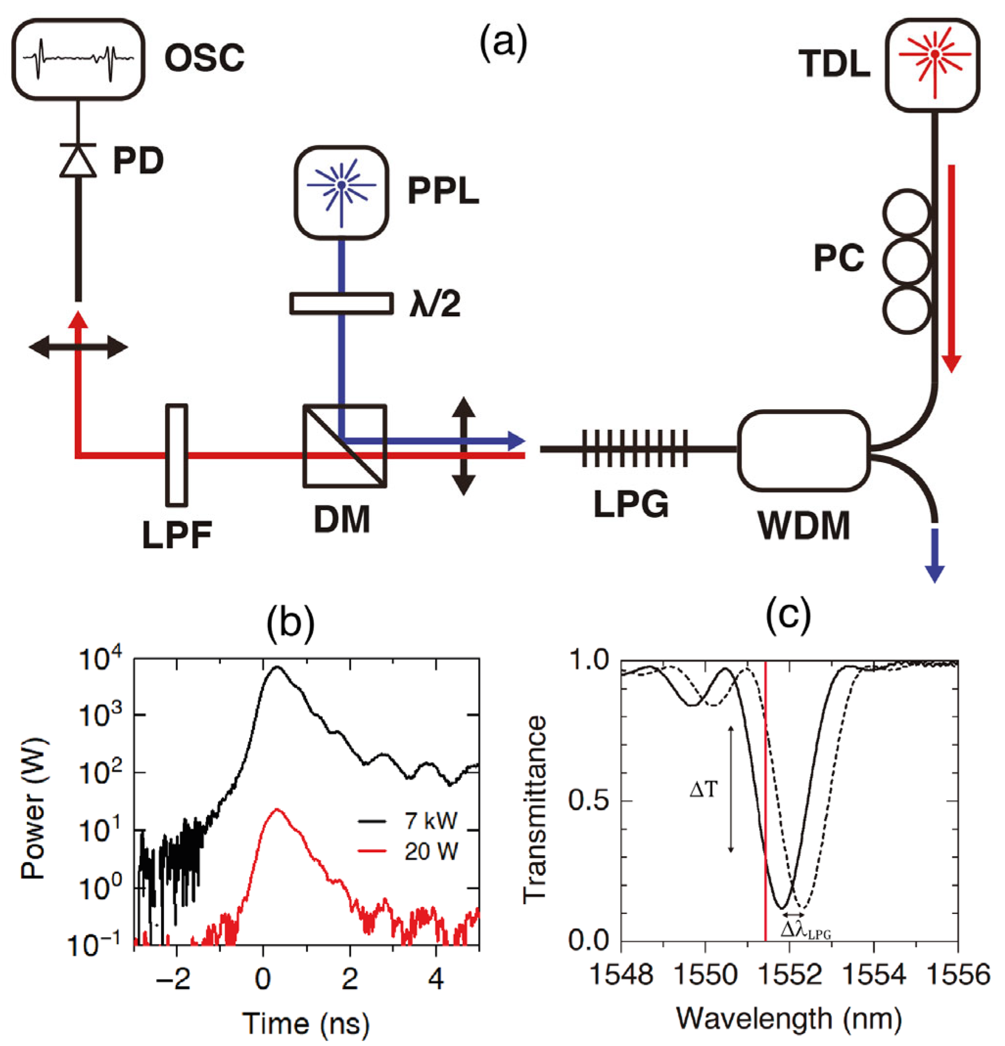
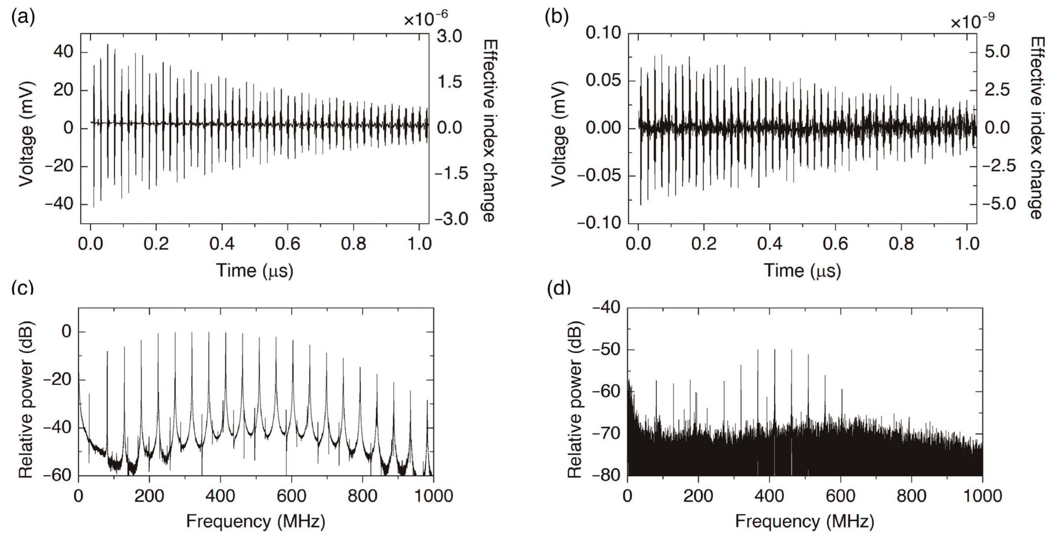
In-fiber opto-mechanics based on forward Brillouin scattering enables sensing the surrounding of the optical fiber. Optical fiber transverse acoustic resonances are sensitive to both the inner properties of the optical fiber and the external medium. A particularly efficient pump and probe technique—assisted by a fiber grating—can be exploited for the development of point sensors of only a few centimeters in length. When measuring the acoustic resonances, this technique provides the narrowest reported linewidths and a signal-to-noise ratio better than 40 dB. The longitudinal and transverse acoustic velocities—normalized with the fiber radius—can be determined with a relative error lower than 10−4, exploiting the derivation of accurate asymptotic expressions for the resonant frequencies.
1. Introduction
2. A Point Pump and Probe Technique


3. Asymptotic Expressions for High-Order Resonances
The characteristic equations for R0,m and TR2,m resonances are:
where z is the normalized frequency given by z = 2πa f /VS, and α = VS/VL, with f being the frequency, a the fiber radius, VS and VL the shear and longitudinal acoustic wave velocities, and Jm the Bessel functions of the first kind of order, m.
4. Sensor Applications
4.1. High-Accuracy Measurement of Poisson’s Ratio
4.2. Simultaneous Strain and Temperature Measurement with a Single-Point Sensor
Here, the implementation of simultaneous and discriminative measurements of strain (ε) and temperature using a single-point sensor that exploits the FBS pump and probe technique is discussed. The proposed approach exploits the different sensitivities of radial, , and torsional-radial, , resonances with strain and temperature, generated by the different temperature and strain coefficients of the longitudinal and shear acoustic wave velocities (∂VL/∂T ≠ ∂VS/∂T and ∂VL/∂ε ≠ ∂VS/∂ε). In addition, for large values of the order m and according to the asymptotic expressions (4) and (5), we found that the relative shift of all the resonance frequencies of radial modes versus temperature and strain, , will be independent of the order m, and the same happens for the relative shift of the torsional-radial resonances, . Thus, instead of measuring only one radial resonance and one torsional-radial resonance, it can be more robust to measure several of them, or even the whole spectrum. Figure 4 shows the relative frequency shift of two specific resonances and the averaged value obtained using the whole spectrum, showing that there is a perfect agreement. From these measurements, one can calibrate the sensor and obtain the temperature and strain coefficients for and defined by the elements of the following 2 × 2 matrix:

References
- Shelby, R.M.; Levenson, M.D.; Bayer, P.W. Guided acoustic-wave Brillouin scattering. Phys. Rev. B 1985, 31, 5244–5252.
- Zadok, A.; Diamandi, H.H.; London, Y.; Bashan, G. Forward Brillouin Scattering in Standard Optical Fibers: Single-Mode, Polar-ization-Maintaining, and Multi-Core, 1st ed.; Springer: Cham, Switzerland, 2022.
- Kang, M.S.; Brenn, A.; Wiederhecker, G.S.; Russell, P.S. Optical excitation and characterization of gigahertz acoustic resonances in optical fiber tapers. Appl. Phys. Lett. 2008, 93, 131110.
- Kang, M.S.; Nazarkin, A.; Brenn, A.; Russell, P. Tightly trapped acoustic phonons in photonic crystal fibres as highly nonlinear artificial Raman oscillators. Nat. Phys. 2009, 5, 276–280.
- Beugnot, J.-C.; Lebrun, S.; Pauliat, G.; Maillotte, H.; Laude, V.; Sylvestre, T. Brillouin light scattering from surface acoustic waves in a subwavelength-diameter optical fibre. Nat. Commun. 2014, 5, 5242.
- Chow, D.M.; Yang, Z.; Soto, M.A.; Thévenaz, L. Distributed forward Brillouin sensor based on local light phase recovery. Nat. Commun. 2018, 9, 2990.
- Pang, C.; Hua, Z.; Zhou, D.; Zhang, H.; Chen, L.; Bao, X.; Dong, Y.K. Opto-mechanical time-domain analysis based on coherent forward stimulated Brillouin scattering probing. Optica 2020, 7, 176–184.
- Alcusa-Sáez, E.P.; Díez, A.; Rivera-Pérez, E.; Margulis, W.; Norin, L.; Andrés, M.V. Acousto-optic interaction in polyimide coated optical fibers with flexural waves. Opt. Express 2017, 25, 17167–17173.
- Diamandi, H.H.; London, Y.; Bashan, G.; Zadok, A. Distributed opto-mechanical analysis of liquids outside standard fibers coated with polyimide. Appl. Phys. Lett. Photonics 2019, 4, 016105.
- Bashan, G.; Diamandi, H.H.; London, Y.; Preter, E.; Zadok, A. Optomechanical time-domain reflectometry. Nat. Commun. 2018, 9, 2991.
- Diamandi, H.H.; London, Y.; Bashan, G.; Shemer, K.; Zadok, A. Forward Stimulated Brillouin Scattering Analysis of Optical Fibers Coatings. J. Light. Technol. 2021, 39, 1800–1807.
- Poveda-Wong, L.; Cruz, J.L.; Delgado-Pinar, M.; Roselló-Mechó, X.; Díez, A.; Andrés, M.V. Fabrication of long period fiber gratings of subnanometric bandwidth. Opt. Lett. 2017, 42, 1265–1268.
- Biryukov, A.S.; Sukharev, M.E.; Dianov, E.M. Excitation of sound waves upon propagation of laser pulses in optical fibres. Quantum Electron. 2002, 32, 765–775.
- Antman, Y.; Clain, A.; London, Y.; Zadok, A. Optomechanical sensing of liquids outside standard fibers using forward stimulated Brillouin scattering. Optica 2016, 3, 510–516.
- Olver, F.W.J. Bessel Functions of integer order. In Handbook of Mathematical Functions with Formulas, Graphs and Mathematical Tables, 10th ed.; Abramowitz, M., Stegun, I.A., Eds.; National Bureau of Standards Applied Mathematics Series No. 55; U.S. Government Printing Office: Washington, DC, USA, 1972; pp. 364–365.
- Sánchez, L.A.; Díez, A.; Cruz, J.L.; Andrés, M.V. High accuracy measurement of Poisson’s ratio of optical fibers and its temperature dependence using forward-stimulated Brillouin scattering. Opt. Express 2022, 30, 42–52.
- Bertholds, A.; Dandliker, R. Determination of the individual strain-optic coefficients in single-mode optical fibres. J. Light. Technol. 1988, 6, 17–20.
- El-Diasty, F. Multiple-beam interferometric determination of Poisson's ratio and strain distribution profiles along the cross section of bent single-mode optical fibers. Appl. Opt. 2000, 39, 3197–3201.
- L. A. Sánchez, A. Díez, J. L. Cruz, and M. V. Andrés High accuracy measurement of Poisson’s ratio of optical fibers and its temperature dependence using forward-stimulated Brillouin scattering. Optics Express 2022, 30, 42, https://doi.org/10.1364/OE.442295.


