Your browser does not fully support modern features. Please upgrade for a smoother experience.
Submitted Successfully!
 +1 credit
Thank you for your contribution! You can also upload a video entry or images related to this topic.
For video creation, please contact our Academic Video Service.
| Version | Summary | Created by | Modification | Content Size | Created at | Operation |
|---|---|---|---|---|---|---|
| 1 | Michel Feidt | -- | 1704 | 2023-02-06 09:59:08 | | | |
| 2 | Catherine Yang | + 1 word(s) | 1705 | 2023-02-06 10:05:03 | | |
Video Upload Options
We provide professional Academic Video Service to translate complex research into visually appealing presentations. Would you like to try it?
Cite
If you have any further questions, please contact Encyclopedia Editorial Office.
Costea, M.; Feidt, M. Technologies of Combined Heat and Power Production. Encyclopedia. Available online: https://encyclopedia.pub/entry/40863 (accessed on 25 July 2026).
Costea M, Feidt M. Technologies of Combined Heat and Power Production. Encyclopedia. Available at: https://encyclopedia.pub/entry/40863. Accessed July 25, 2026.
Costea, Monica, Michel Feidt. "Technologies of Combined Heat and Power Production" Encyclopedia, https://encyclopedia.pub/entry/40863 (accessed July 25, 2026).
Costea, M., & Feidt, M. (2023, February 06). Technologies of Combined Heat and Power Production. In Encyclopedia. https://encyclopedia.pub/entry/40863
Costea, Monica and Michel Feidt. "Technologies of Combined Heat and Power Production." Encyclopedia. Web. 06 February, 2023.
Copy Citation
The combined hot heat and power (CHHP) terminology adopted nowadays is more representative than the CHP that was designated at the end of 19th century, the first combination of useful effects of the electricity production based on the thermomechanical engine industry. The two useful effects of CHHP, electricity and heat, are differentiated by priority, together with the corresponding first law efficiency expressions.
combines heat and power
trigeneration
environmental impacts
thermodynamic modelling
constraints
1. Gas Engine CHHP
This alternative uses an internal combustion engine fueled with natural gas or biogas.
Figure 1 illustrates the configuration of a gas engine CHHP. The engine could be fueled with natural gas from the network (at a pressure of 4 bar). Generally, the produced electricity is of low voltage or mean voltage for industrial applications (power).
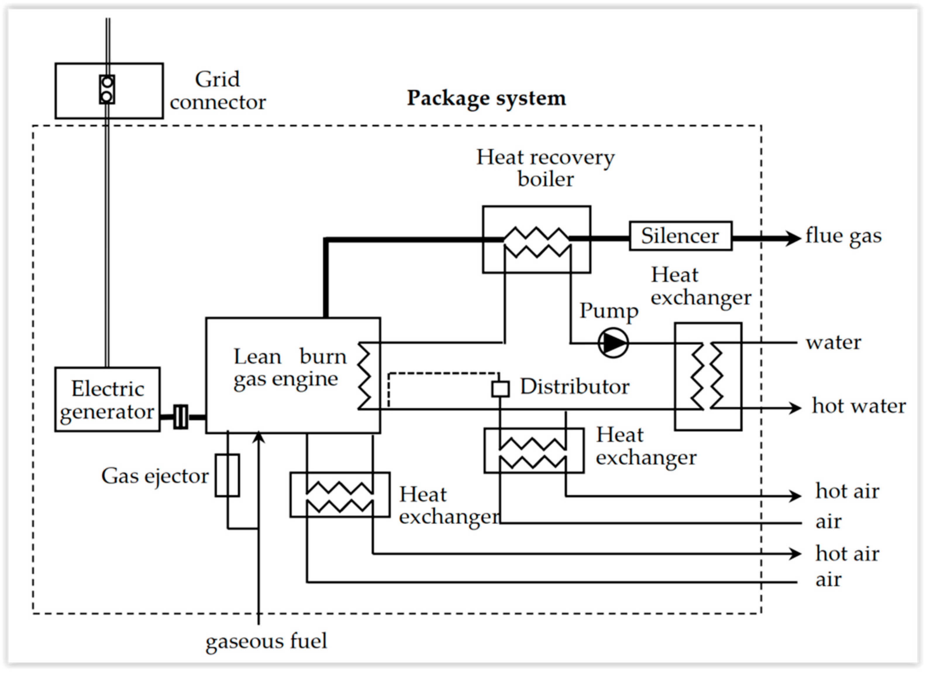
Figure 1. Schematic diagram of a gas engine cogeneration unit [1].
Heat is recuperated as warm water from various heat exchangers: cooling lubricant, cooling exhaust gas (flue gases), cooling turbocharger. The main use seems to be in the tertiary domain, with 1 MW order of magnitude (building, hospital, university) [2].
2. Gas Turbine CHHP
Figure 2 represents such a system. The air is compressed (within the range 15 to 40 bar) in a turbocompressor, before being introduced in the combustion chamber, where it maintains the burning of liquid fuel or natural gas. After the combustion, the flue gas is expanded in the turbine coupled to the alternator to produce electricity. Part of the mechanical energy produced by the gas turbine is used to drive the compressor.
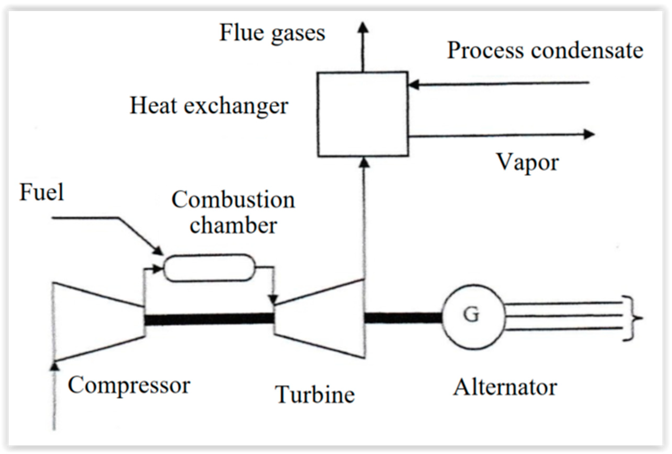
Figure 2. Scheme of a CHHP with Gas Turbine engine [3].
The exhaust gases (flue gases) are at 450–550 °C, while the combustion temperature is 850–1200 °C. Sensible heat could be recuperated in heat exchangers or within a post-combustion chamber.
Gas turbine engine CHHP is mainly used for power upper to 1 MW. Examples are available in the following sections. The researchers indicate that the new tendency is to consider microturbines [4][5][6].
3. Diesel Engine
This CHHP configuration is interesting, due to the high value of the first law efficiency of the diesel engine over a large domain of power output, the flexibility of the fuel that can be used, and the large variety of CHHP configurations. The recuperated heat comes from three sources: (1) exhaust gases, (2) engine cooling water (around 110 °C) or low-pressure vapor (about 0.5 bar), (3) engine lubricant cooling.
The industrial use of this configuration is not so evident, but it is well-adapted for air conditioning systems. Generally, the diesel CHHP systems have a lower global first law efficiency, due to the low thermal recuperated heat associated with high mechanical efficiency.
4. Vapor Engine
This CHHP configuration uses a back pressure vapor turbine (with an exit pressure higher than the ambient one) [6][7].
Its main use is in industry where it ensures the delivery of water vapor in the networks (generally at 3 bar or 12 bar). The water vapor could be also extracted during its expansion in the turbine [6].
5. CHHP with Combined Cycles
In this case, there is a coupling between a gas turbine and a vapor turbine (Figure 3). The heat rejection of the gas turbine is used to produce water vapor for the vapor turbine. Many variants of this system exist [6][8].
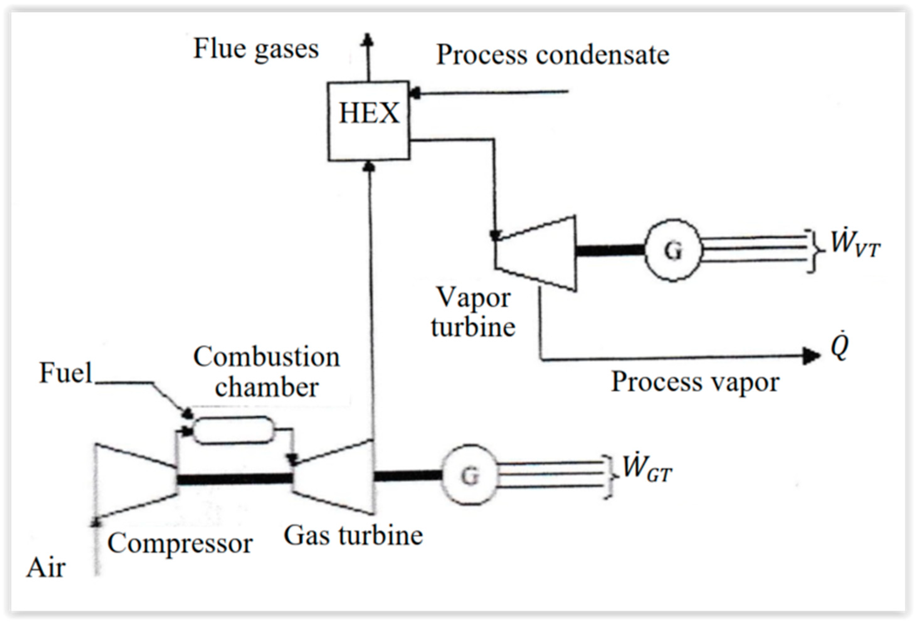
Figure 3. Combined cycle Gas Turbine + Vapor Turbine and cogeneration [6].
The high efficiency of the conversion from chemical (fuel) energy to the electrical one implies that the rejected heat from the gas turbine tends to be low, since the main interest is to produce water vapor for industrial use.
6. External Combustion Engine CHHP
The two main types of external combustion engines are the Stirling [9][10] and Ericsson [9] configurations. These two cycles are also used for reverse cycle applications (cold production). Note that the Stirling configuration is present in more applications than the Ericsson one. A great advantage of these systems consists of the fact that external combustion control is easier with whatever fuel is used. Additionally, external heat source does not exclude other configurations, for example, solar ones [11]. Complementary references on the subject with specific configurations are given in [12][13][14].
7. Fuel Cells
The most common fuel cell (FC) uses the reciprocal chemical transformation of water dissociation (electrolysis of water), according to:
where H2 is the fuel, and O2 is the oxidizer.
This chemical reaction is environmentally safe because it produces only water. The fuel H2 could also be produced from natural gas, liquefied petroleum gas (LPG), or other fuels by chemical reaction with the catalysis that is used to boost the electrochemical reaction.
Globally, the electrochemical reaction produces electrical energy and heat. The first law of efficiency for electrical production is around 50%, according to the fuel cell architecture.
If H2 is produced from a hydrocarbon species, CO2 emission is identical to one of the most performant diesel engines, due to the functional temperature of FC in the range of 80 °C for PEMFC (proton exchange membrane fuel cell) and 1000 °C for SOFC (solid oxide fuel cell). However, the rejection of NOx is suppressed, as well as the sulfur oxides.
The rejected heat recovery essentially depends on the level of temperature rejection. In this respect, SOFC [15][16] could turn a gas turbine, due to their high temperature rejection, and thus improve the first law efficiency for electricity production, always with an interesting level of temperature for the remaining heat rejection.
Even if FC are well-studied, their applications seem to remain rather demonstrative projects.
8. Comparison and Some Other Possibilities
Table 1 summarizes the advantages and inconveniences of the three main configurations of CHHP, apart from industrial uses.
Table 1. Comparison of three cogeneration systems.
| Cogeneration System | Gas Turbine | Gas Engine | Diesel Engine |
|---|---|---|---|
| Power range | 1–230 MW | 0.2–5 MW | 0.15–10 MW |
| Fuel used | Heavy oil, kerosene, biogas | LPG, biogas | Heavy oil, kerosene |
| Flue gas temperature | 500–600 °C | 400–600 °C | 350–400 °C |
| Cooling water temperature | - | 80–90 °C | 70–75 °C |
| Efficiency of the electricity production | 25–40% | 28–38% | 30–45% |
| Total efficiency | 60–85% | 60–80% | 40–70% |
More recently, some new configurations of CHHP appear, for example, based on solar energy conversion, namely:
-
Thermal configuration of solar CHHP, for example the dish Stirling [14] engine, where solar energy is the hot source ensuring heat to mechanical energy conversion,
-
Photovoltaic and thermal conversion (PVT).
This more recent approach considers the direct conversion of radiative solar energy to electricity, while the remaining heat could be used for air conditioning (heating or cooling), as well as hot water production.
Actually, the situation is very contrasted, due to the importance of the laws and specificities of nations. In France, the cogeneration is poorly used (3% around 2000), due to the high weight of nuclear energy in the electricity production. Thereby, cogeneration is used for the industry heat network and tertiary domain (hospital, buildings, university).
In Europe, according to Cogen Europe [17], the cogeneration in 2000 was 10% of the total production, with 50% in industry (chemistry, paper, petroleum industry). Eurostat [18] provides an interesting repartition of used fuel (Figure 4) and technologies (Figure 5).
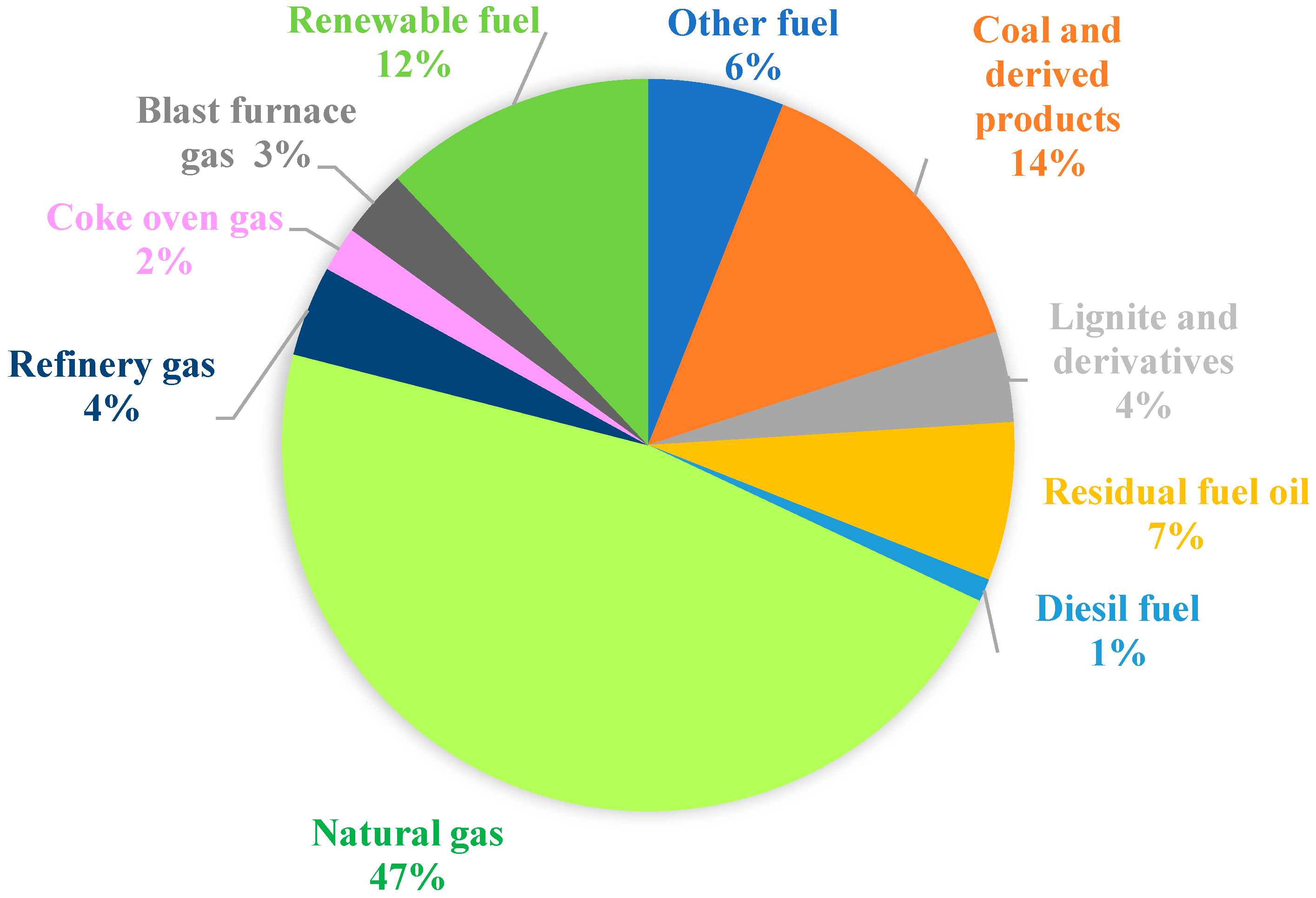
Figure 4. Use of different types of fuel [18].
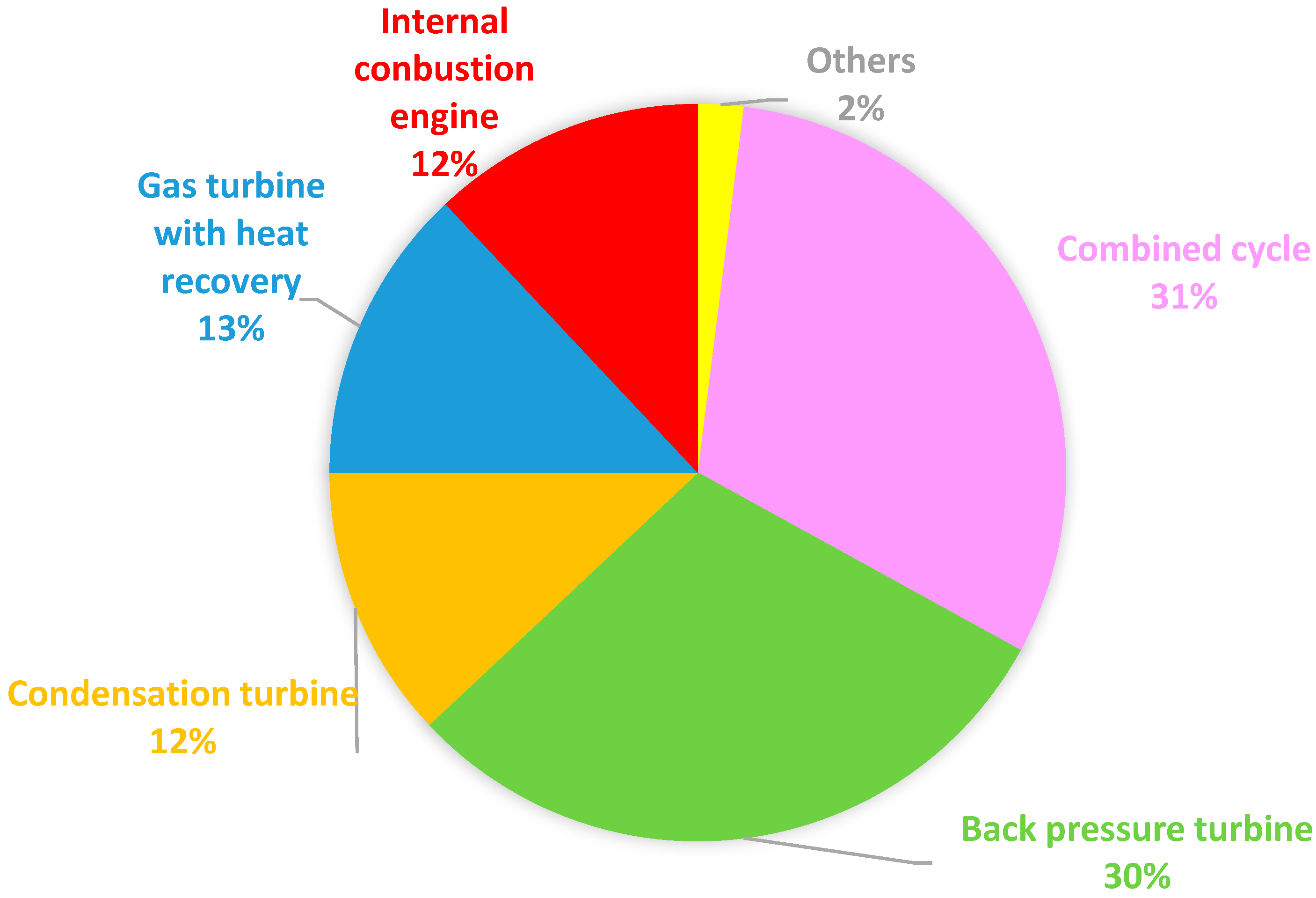
Figure 5. Electricity production distribution among different CHP systems in EU [18].
Figure 4 shows that the most used fuel in EU is natural gas (47%), followed by coal and derived products (14%) and renewable fuel (12%), while the weight of the other fuels is below 10%.
Figure 5 confirms that the vapor turbine is dominant in the EU, with 73% of usage, since it is present in condensation turbines (12%), back pressure turbines (30%), and combined cycles (31%).
9. Considerations Regarding Efficiencies
9.1. First Law Efficiency of CHHP
The first law of efficiency of CHHP was introduced differently, since its expression depends on the priority of the useful effect given to (i) work or (ii) heat (particularly heat networks).
Figure 6 shows the first law efficiency values for different CHP power plants and the main cogeneration systems in EU countries, with the average of the 15 countries, followed by the distribution of each of them. It appears that the combined cycle efficiency is the highest in Denmark, Germany, Luxembourg, Sweden, and Finland, but modest on EU-15 (about 52%), while the CHHP using the back pressure turbine have the highest efficiency in Spain, France, Ireland, Italy, Netherlands, and UK, as well as an average on EU-15 (about 79%).
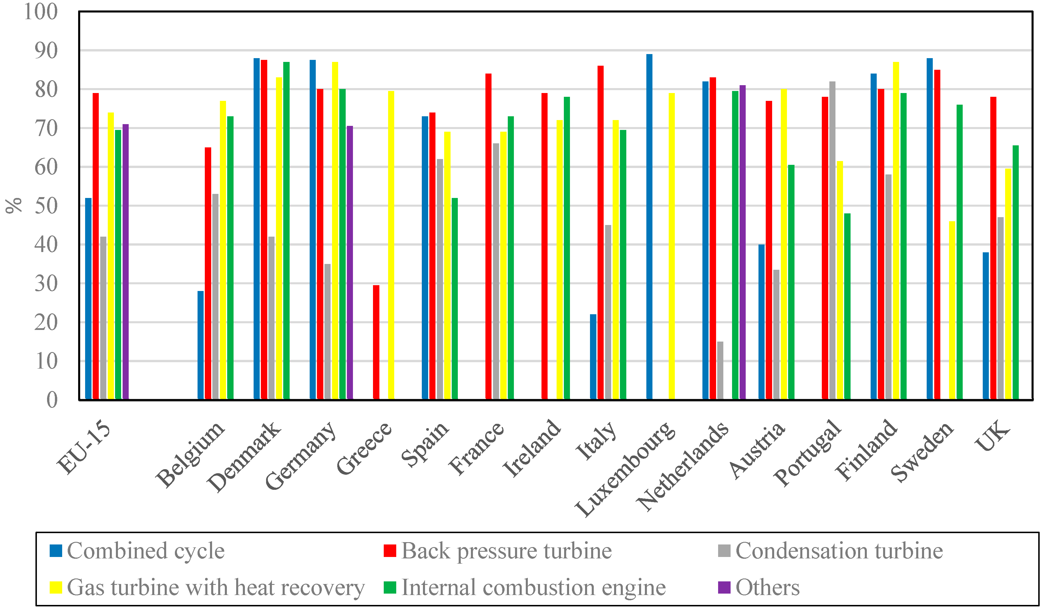
Figure 6. First law efficiency of different CHP systems in EU [18].
The configuration with condensation and steam extraction is less efficient, with an average of the first law efficiency about 42% for EU-15, but the criterion used is doubtful.
9.2. First Law Efficiency for Trigeneration
The general definition of the first law of efficiency in the case of trigeneration involves three useful effects:
-
Hot heat flux ,
-
Cold heat flux ,
-
Power output , with the steady-state operation assumption.
The energy rate expense is generally heat flux, . Thus, the first law efficiency expression for trigeneration is:
The value of this efficiency is less than 1, due to the thermal losses rate of the system and rejected heat rate, . By considering these two heat rates, an equivalent expression of the first law efficiency for trigeneration results in:
Figure 7 illustrates a general scheme of the heat flow in a trigeneration system, starting with:
-
E—the primary heat, from the source to the system,
-
H—the hot heat delivery,
-
C—cold heat delivery,
-
R—heat rejected to the sink.
Note that the important issues associated with trigenerations are considered and discussed in [19].
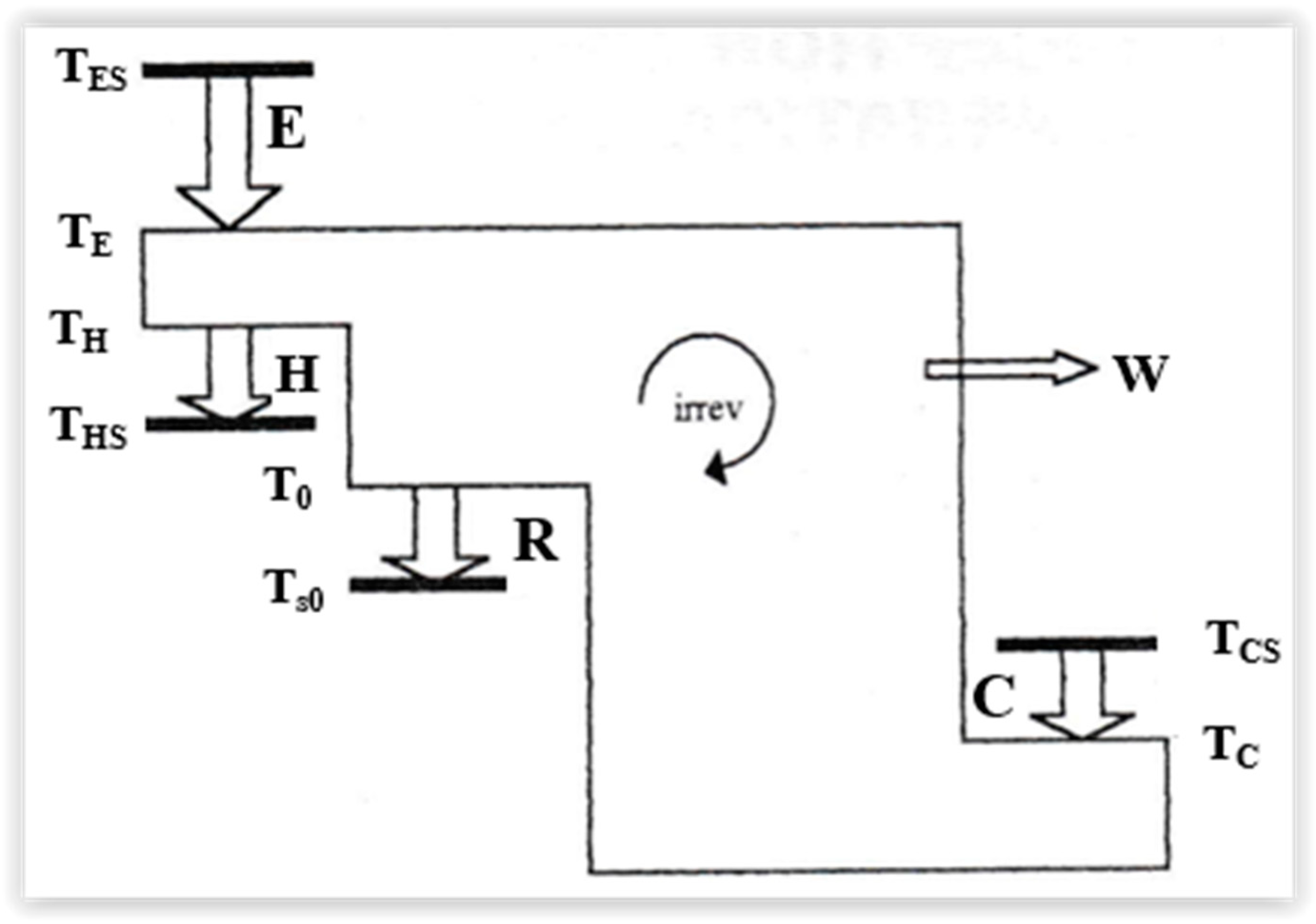
Figure 7. Scheme of a general trigeneration configuration [19].
9.3. Exergy Efficiency
The exergy efficiency indicator is a useful tool for maximizing the benefit and efficiently using the resources [20]. It allows us to emphasize the losses and internal irreversibilities leading to the reduction of the energy potential to produce useful effects.
It is well-known that the heat rate exergy is expressed as the product of the Carnot efficiency and the heat rate [20]:
where T0 is the ambient temperature, and T is the temperature at which the heat transfer occurs.
Replacing the various heat rate terms in the first law efficiency (Equation (3)) with the corresponding heat rate exergy from Equation (5) provides the expression of the exergy efficiency for trigeneration:
with THS, hot heat effect temperature > T0,
TCS, cols heat effect temperature < T0,
TES, primary heat effect temperature > THS.
This temperatures associated to the heat rates delivery are indicated by bold lines in Figure 7.
References
- Thiers, S.; Aoun, B.; Peuportier, B. Experimental characterization, modelling and simulation of a wood pellet micro-combined heat and power unit used as a heat source for residential building. Energy Build. 2010, 42, 896–903.
- Löffler, P. Research Executive GOGEN EUROP. In Proceedings of the Communication in Seminar on Decentralized Energy, Paris, France, 15 October 2002. (In French).
- Costea, M.; Feidt, M.; Alexandru, G.; Descieux, D. Optimisation of gas turbine cogeneration system for various heat exchanger configuration. Oil Gas Sci. Technol. 2012, 67, 517–535.
- Sepehr, S.; Masoud, Z.; Maziar, G. Optimal design of gas turbine CHP plant with preheater and HRSG. Int. J. Energy Res. 2009, 33, 766–777.
- Postelnicu, V. Micro Cogeneration—Micro Gas Turbine. Master’s Thesis, National Polytechnic Institute of Lorraine, Nancy, France, 2003. (In French).
- Cenusa, V. Contribution to the improvement of the Thermodynamic Coupling between the Gas Turbine Installation and the Steam Turbine Installation of A Gas-Steam Combined Cycle Power Plants. Ph.D. Thesis, University Henri Poincaré (Lorraine University now), Nancy, France, 25 October 2006. (In French).
- Remy, P.M.; Boissenin, Y.M.; Moliere, M.M. Combustion turbine and cogeneration facilities with complex architecture: Example of the Metz electricity plant. Int. J. Thermal Sci. 1994, 396, 717–725. (In French)
- Starfelt, F.; Yan, J.Y. Case study of energy systems with gas turbine cogeneration technology for industrial peek. Int. J. Energy Res. 2008, 12, 1128–1135.
- Stouffs, P. Micro cogeneration: Choice of heat engine. Bul. Inst. Poli. Iasi 2010, 56, 3a. Machine Construction section. (In French)
- Boucher, J.; Garcia Burel, I.; Lanzetta, F.; Nika, P. Parametric study of the performance of a Duval-type free-piston cogenerator. In Proceedings of the French Thermal Congress SFT 2007, Île des Embiez, France, 29 May–1 June 2007; pp. 1139–1144. (In French).
- Mathieu, A. Contribution to the Conception and Thermodynamic Optimization of A Solar Thermoelectric Micro Power Plant. Ph.D. Thesis, Lorraine University, Nancy, France, 23 May 2012. (In French).
- Mikalsen, R.; Roskilly, A.P. A review of free-piston engine history and applications. Appl. Thermal Eng. 2007, 27, 2339–2352.
- Francois, P.; Garcia Burel, I.; Ben Ahmed, H.; Prevond, L.; Multon, B. 3D Analytical model for a tubular linear induction generator in a Stirling cogeneration system. In Proceedings of the IEEE IEMDC, Antalya, Turkey, 3–5 May 2007; pp. 392–397, hal-00676232.
- Schaechtele, K.; Nepveu, F.; Ferriere, A. Technical and Economic Study of the Dish-Stirling System: Methodology Based on a Multi-Criteria Analysis Technique; Report PROMES-CNRS: Paris, France, 2006. (In French)
- Radulescu, M. Electricity Cogeneration System with Pemfc or Sofc Type Fuel Cell and Internal Reforming. Ph.D. Thesis, University Henri Poincaré (Lorraine University now), Nancy, France, 25 September 2006. (In French).
- Gay, C. Improving the Energy Efficiency of the Vehicle of the Future: Stirling Engine/Sofc Fuel Cell Association. Ph.D. Thesis, University of Franche Comté, Besançon, France, 19 October 2008. (In French).
- Europe, C. A Guide to Cogeneration; Technical Report; Cogen Europe: Brussel, Belgium, 2000.
- Quel Futur Pour L’humanité. Available online: htttp://www.quelfutur.org/consommationeurope.html (accessed on 7 July 2022). (In French).
- Feidt, M.; Lang, S. Optimal design of combined systems generating power, heat, force. Entropie 2002, 242, 2–11. (In French)
- Dincer, I.; Zamfirescu, C. Advanced Power Generation Systems, 1st ed.; Elsevier: Amsterdam, The Netherlands, 2014; pp. 27–49.
More
Information
Subjects:
Engineering, Electrical & Electronic
Contributors
MDPI registered users' name will be linked to their SciProfiles pages. To register with us, please refer to https://encyclopedia.pub/register
:
View Times:
1.1K
Revisions:
2 times
(View History)
Update Date:
06 Feb 2023
Table of Contents


Notice
You are not a member of the advisory board for this topic. If you want to update advisory board member profile, please contact office@encyclopedia.pub.
OK
Confirm
Only members of the Encyclopedia advisory board for this topic are allowed to note entries. Would you like to become an advisory board member of the Encyclopedia?
Yes
No
${ textCharacter }/${ maxCharacter }
Submit
Cancel
Back
Comments
${ item }
|
${ item.createdUser.fullName }
${ item.createdAt }
${ item.vote }
${ item.reply }
Delete
${ reply.createdUser.fullName }
${ reply.createdAt }
${ reply.vote }
Delete
There is no reply to this comment~
${ item.replyTextCharacter }/${ item.replyMaxCharacter }
Submit
Cancel
More
No more~
There is no comment~
${ textCharacter }/${ maxCharacter }
Submit
Cancel
${ selectedItem.replyTextCharacter }/${ selectedItem.replyMaxCharacter }
Submit
Cancel
Confirm
Are you sure to Delete?
Yes
No