| Version | Summary | Created by | Modification | Content Size | Created at | Operation |
|---|---|---|---|---|---|---|
| 1 | NATHIRULLA SHERIFF | -- | 1389 | 2023-01-18 08:51:39 | | | |
| 2 | Amina Yu | -14 word(s) | 1375 | 2023-01-19 01:49:17 | | |
Video Upload Options
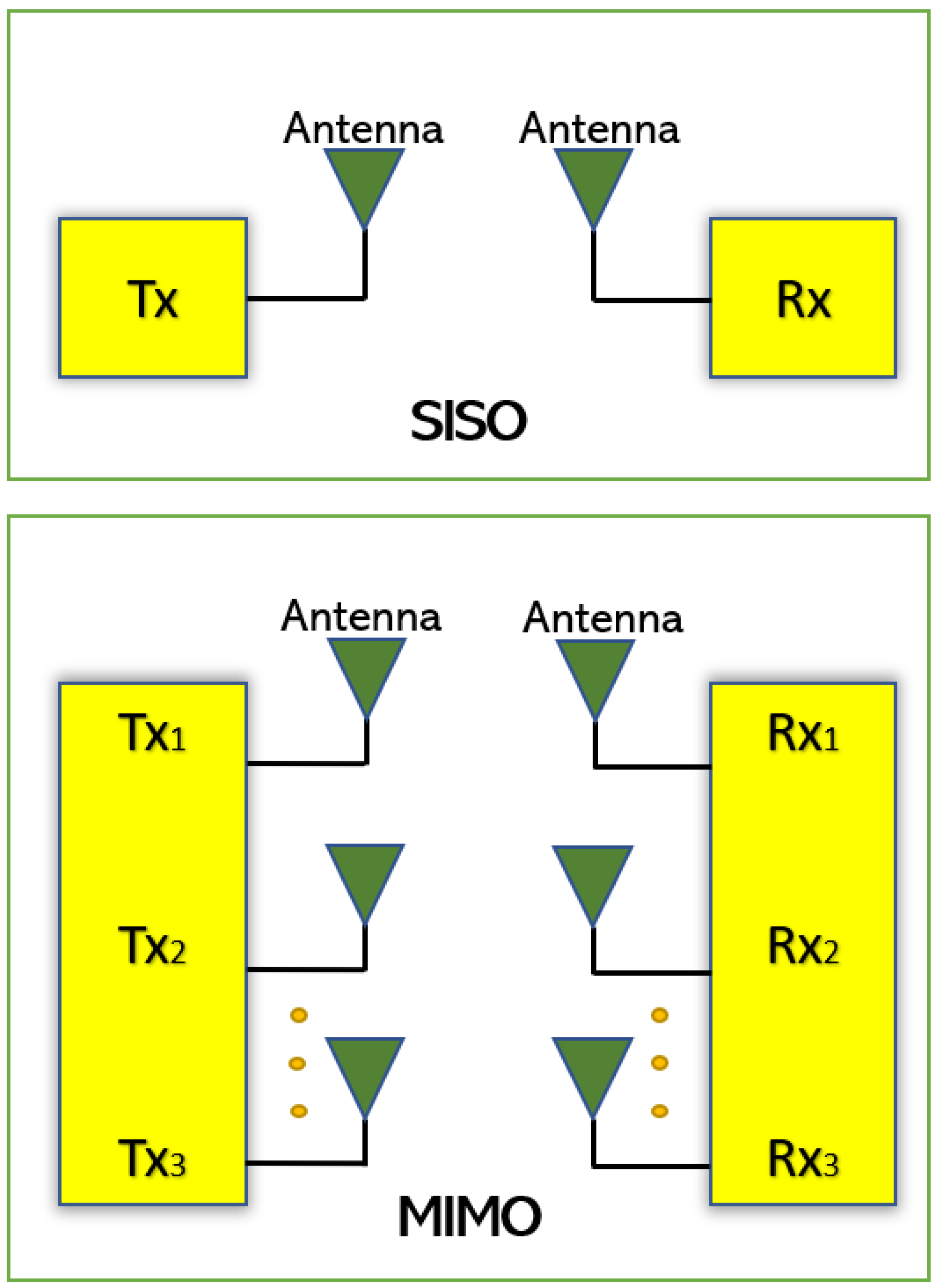
In response to the increasing demand for voice, data, and multimedia applications, the next generation of wireless communication systems is projected to provide faster data rates and better service quality to customers. Techniques such as Multiple-Input–Multiple-Output (MIMO) and diversity are being studied and implemented to meet the needs of next-generation wireless communication systems. Embedding multiple antennas into the same antenna system is seen as a promising solution, which can improve both the system’s channel capacity and the communication link’s quality. For small handheld and portable devices, embedding many antennas into a single device in a small area and at the same time providing good isolation becomes a challenge.
1. Introduction
2. Mathematical Concepts of MIMO


| Acronyms | Meanings |
|---|---|
| SISO | Single Input Single Output |
| MIMO | Multiple Input Multiple Output |
| TARC | Total Active Reflection Coefficient |
| ECC | Envelop Correlation Coefficient |
| DG | Diversity Gain |
| DGS | Defected Ground Structure |
| DMN | Decoupling and matching network |
| CDRN | Coupled Resonator Decoupling Network |
| CSRR | Complementary Split Ring Resonators |
| ACS | Asymmetric Coplanar Strip |
| CPW | Co Planar Waveguide |
| CE | Common Element |
| PIFA | Planar Inverted-F antenna |
| iMAT | Isolated Mode Antenna Technology |
| EBG | Electromagnetic Bandgap |
| MEG | Mean Effective Gain |
| WiFi | Wireless Fidelity |
| UWB | Ultra-Wide Band |
| LTE | Long-Term Evolution |
| WiMax | Worldwide Interoperability for Microwave Access |
The mean effective gain (MEG) is an important performance parameter and can be defined as the ratio of the mean power received to the mean incident power of the antenna. It is used to calculate the average received signal strength of each antenna [12]. Another performance parameter, which is the total active reflection coefficient (TARC) is the ratio of square root of total reflected powers to the total incident powers [13][14]. The TARC is a function of frequency and is expressed in Equations (2) and (3).


 Like the above parameters, the dielectric substrate permittivity, loss tangent and thickness play an important role in designing the antennas. The efficiency, return loss and gain can also be improved by the proper selection of the dielectric material.
References
- Liu, H.; Yang, W.; Zhang, A.; Zhu, S.; Wang, Z.; Huang, T. A Miniaturized Gain-Enhanced Antipodal Vivaldi Antenna and Its Array for 5G Communication Applications. IEEE Access 2018, 6, 76282–76288.
- Takahashi, K.; Arai, H.; Ihara, T.; Ishikawa, Y. A study of antenna configuration and channel capacity about MIMO. In Proceedings of the 2015 IEICE Society Conference, Tokyo, Japan, 16–18 September 2015.
- Rohani, B.; Arai, H. Enhancing 4× 4 MIMO channel capacity by dual polarized directional antenna. In Proceedings of the IEICE General Conference, Yokohama, Japan, 28–31 March 2016; p. 181.
- Nadeem, I.; Choi, D.-Y. Study on Mutual Coupling Reduction Technique for MIMO Antennas. IEEE Access 2018, 7, 563–586.
- Roy, S.; Ghosh, S.; Chakarborty, U. Compact dual wide-band four/eight elements MIMO antenna for WLAN applications. Int. J. RF Microw. Comput. Eng. 2019, 29, e21749.
- Dixit, A.S.; Kumar, S. A miniaturized antipodal Vivaldi antenna for 5G communication applications. In Proceedings of the 2020 7th International Conference on Signal Processing and Integrated Networks (SPIN), Noida, India, 27–28 February 2020.
- Seyyedesfahlan, M.; Uzun, A.; Skrivervik, A.; Tekin, I. Wideband Multiport Antennas. Sensors 2020, 20, 6960.
- Vaughan, R.; Andersen, J. Antenna diversity in mobile communications. IEEE Trans. Veh. Technol. 1987, 36, 149–172.
- Mattheijssen, P.; Herben, M.; Dolmans, G.; Leyten, L. Antenna-Pattern Diversity Versus Space Diversity for Use at Handhelds. IEEE Trans. Veh. Technol. 2004, 53, 1035–1042.
- Chouhan, S.; Panda, D.K.; Gupta, M.; Singhal, S. Multiport MIMO antennas with mutual coupling reduction techniques for modern wireless transreceive operations: A review. Int. J. RF Microw. Comput. Eng. 2017, 28, e21189.
- Votis, C.; Tatsis, G.; Kostarakis, P. Envelope Correlation Parameter Measurements in a MIMO Antenna Array Configuration. Int. J. Commun. Netw. Syst. Sci. 2010, 3, 350–354.
- Glazunov, A.A.; Molisch, A.; Tufvesson, F. Mean effective gain of antennas in a wireless channel. IET Microw. Antennas Propag. 2009, 3, 214–227.
- ho Chae, S.; il Kawk, W.; Park, S.O.; Lee, K. Analysis of mutual coupling in MIMO antenna array by TARC calculation. In Proceedings of the 2006 Asia-Pacific Microwave Conference, Yokohama, Japan, 12–15 December 2006; pp. 2090–2093.
- Fritz-Andrade, E.; Jardon-Aguilar, H.; Tirado-Mendez, J.A. The correct application of total active reflection coefficient to evaluate MIMO antenna systems and its generalization to N ports. Int. J. RF Microw. Comput. Eng. 2019, 30, e22113.


