In response to the increasing demand for voice, data, and multimedia applications, the next generation of wireless communication systems is projected to provide faster data rates and better service quality to customers. Techniques such as Multiple-Input–Multiple-Output (MIMO) and diversity are being studied and implemented to meet the needs of next-generation wireless communication systems. Embedding multiple antennas into the same antenna system is seen as a promising solution, which can improve both the system’s channel capacity and the communication link’s quality. For small handheld and portable devices, embedding many antennas into a single device in a small area and at the same time providing good isolation becomes a challenge.
1. Introduction
With the explosive growth in users of present and future technology, there is a pressing need to design new compact antenna systems for higher data rate and large bandwidth. Design and implementation of Single-Input Single-Output (SISO) antennas for portable devices are easy and can be easily integrated into the portable systems. However, SISO systems are susceptible to the problems caused by multipath effect and for obtaining higher gain, the size of a SISO antenna should be increased proportionally
[1]. For antenna to work efficiently at higher data rates in the existing frequency with an improved channel capacity is a great challenge. With the growing demand, designing Multiple-Input Multiple-Output (MIMO) antenna systems is a significant solution
[2][3][2,3]. The MIMO systems precisely provide a technique in which multiple independent channels send and receive data concurrently in the same radio channel. The multiple transmit-and-receive antennas used in MIMO technology improve the radio link capacity to attain the multipath propagation. Next-generation wireless communication technology has presented MIMO systems as a feasible solution to solve the data rate limitation problem experienced by SISO systems, due to its multiple antennas’ capability which can also provide better system reliability and increased channel capacity
[4][5][4,5]. The MIMO antenna system can enhance the signal quality and the gain of an antenna but leads to complexity in design and an increase in size
[6]. To attain a required level of signal independence and good isolation in MIMO operation, the multiple antennas should be placed with adequate separation from each other. But for portable devices, this approach would need to be given more space for multiple antennas, as well as additional feedline length
[7]. The close placement of the antenna elements for MIMO operations can solve the space issue but results in higher mutual coupling among antenna elements.
In this perspective, various isolation techniques and different types of isolation enhancement techniques are found in literature to improve the isolation in various antenna structures which are discussed
in detail in Section 2. Through these techniques, the gain, bandwidth, envelop correlation coefficient (ECC), and efficiency can be enhanced. The antenna diversity technique used in MIMO systems enhances the performance of MIMO systems through multipath fading and co-channel interference reduction
[8][9][8,9]. Depending on the requirement, the diversity gain is achieved by employing different methods such as spatial, polarization, and pattern diversities.
Several findings regarding the potential antenna designs suitable for portable devices and small handheld terminals for the MIMO applications have been described in the literature. Existing literatures discussed
in Section 4 have presented works on numerous MIMO antenna designs. In all these designs, more than one antenna elements are integrated or etched on single substrate to apprehend a compact MIMO antenna. This occupies more space and hence presents a big challenge in the industrial design process.
The shared radiator with multiport arrangement is a good alternative to miniaturizing the overall size of MIMO antennas. However, due to the difficulties in getting high isolation among connected ports, only a countable number of antenna designs having shared radiators with more than one port are available in literature. Compared to the array designs and separated ports, there is much less focus on common radiator designs with multiple feeding ports. To regulate mutual coupling, these coupled ports with the shared radiator require extra effort. Thus, designing an antenna becomes critical while considering the required parameters suitable for portable devices.
Currently, we could not find any related review paper accessible could not be found in the literature which can provide us in detail about the shared radiator multiport MIMO antenna systems and their performance improvement techniques. So, herein, there isin this paper, we have endeavoured to explore all the multiport MIMO antennas with a shared radiator, presented in recent years in a holistic manner considering their performance-enhancing techniques and aims to address the design issues for the further advancement in the MIMO antenna design as per their application. TheOur main aim herein this paper is to provide a comprehensive literature review of multiport MIMO antenna systems having one shared radiator and a comparative study on different multiport-shared radiator antenna designs and the isolation improvement techniques used in these designs. The primary antenna features of shared radiator multiport MIMO antennas such as gain, frequency, mutual coupling, ECC and their applications are reviewed and compared herein this paper. In addition, a brief overview of MIMO mathematical concepts and approaches used in these antenna designs for increasing the isolation are also discussed.
2. Mathematical Concepts of MIMO
In this section, the mathematical concepts for MIMO antenna design are discussed
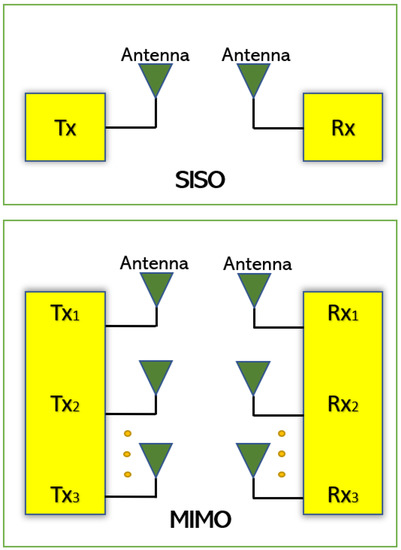
[10]. Since the MIMO antenna system has multiple antennas at the transmit side (M
t) and receive end (M
r) as shown in
Figure 1, the MIMO system capacity (C) can be expressed by Equation (1).

where P
T—total input power,
σ2n—noise power, H—channel matrix, H
H—Hermitian transpose of channel matrix and I
Mr—identity matrix.
where P
T—total input power,
σ2n
—noise power, H—channel matrix, H
H—Hermitian transpose of channel matrix and I
Mr—identity matrix.
Figure 1.
SISO and MIMO Antenna system.
Mutual coupling occurs when antenna elements are placed in closed proximity, which results in isolation reduction thus affecting performance. The envelope correlation coefficient (ECC) is required because the S-parameters such as S
12 or S
21 measured in between the ports are inadequate to encompass the effect of all S-parameters. The mutual coupling and return loss at the ports can be used to determine ECC, which helps to find the diversity performance of the MIMO antennas
[11]. The acceptable and standard value of ECC should be less than 0.5 for portable devices. However, the ECC calculation through S-parameters is effective only in case of lossless antenna substrates but in case of lossy antenna substrate, the ECC must be calculated/measured from the antennas’ far-field radiation patterns. In
Table 1, the acronyms and their meanings are included.
Table 1.
Acronyms.
| Acronyms |
Meanings |
| SISO |
Single Input Single Output |
| MIMO |
Multiple Input Multiple Output |
| TARC |
Total Active Reflection Coefficient |
| ECC |
Envelop Correlation Coefficient |
| DG |
Diversity Gain |
| DGS |
Defected Ground Structure |
| DMN |
Decoupling and matching network |
| CDRN |
Coupled Resonator Decoupling Network |
| CSRR |
Complementary Split Ring Resonators |
| ACS |
Asymmetric Coplanar Strip |
| CPW |
Co Planar Waveguide |
| CE |
Common Element |
| PIFA |
Planar Inverted-F antenna |
| iMAT |
Isolated Mode Antenna Technology |
| EBG |
Electromagnetic Bandgap |
| MEG |
Mean Effective Gain |
| WiFi |
Wireless Fidelity |
| UWB |
Ultra-Wide Band |
| LTE |
Long-Term Evolution |
| WiMax |
Worldwide Interoperability for Microwave Access |
The mean effective gain (MEG) is an important performance parameter and can be defined as the ratio of the mean power received to the mean incident power of the antenna. It is used to calculate the average received signal strength of each antenna [12]. Another performance parameter, which is the total active reflection coefficient (TARC) is the ratio of square root of total reflected powers to the total incident powers [13][14][13,14]. The TARC is a function of frequency and is expressed in Equations (2) and (3).


where, [b] = [S][a] and [S] is the antenna’s scattering matrix, vector [a] is the sum of the available incident power at all the ports, vector [b] is the power reflected to the source and a
n, b
n are the nth element of the vector [a] and vector [b] respectively.
Similarly, the antenna Diversity Gain (DG) is a well-known performance parameter used to verify the efficacy of the diversity. It can be defined as the ratio of rise in SNR of mixed signal from a multiple antenna to the SNR from a single antenna in the system. The DG can be calculated using Equation (4).

Like the above parameters, the dielectric substrate permittivity, loss tangent and thickness play an important role in designing the antennas. The efficiency, return loss and gain can also be improved by the proper selection of the dielectric material.