 +1 credit
| Version | Summary | Created by | Modification | Content Size | Created at | Operation |
|---|---|---|---|---|---|---|
| 1 | S M Sajjad Hossain Rafin | -- | 5988 | 2023-01-09 14:58:50 | | | |
| 2 | Amina Yu | -6 word(s) | 5982 | 2023-01-10 02:49:16 | | | | |
| 3 | Amina Yu | Meta information modification | 5982 | 2023-01-10 02:51:53 | | |
Video Upload Options
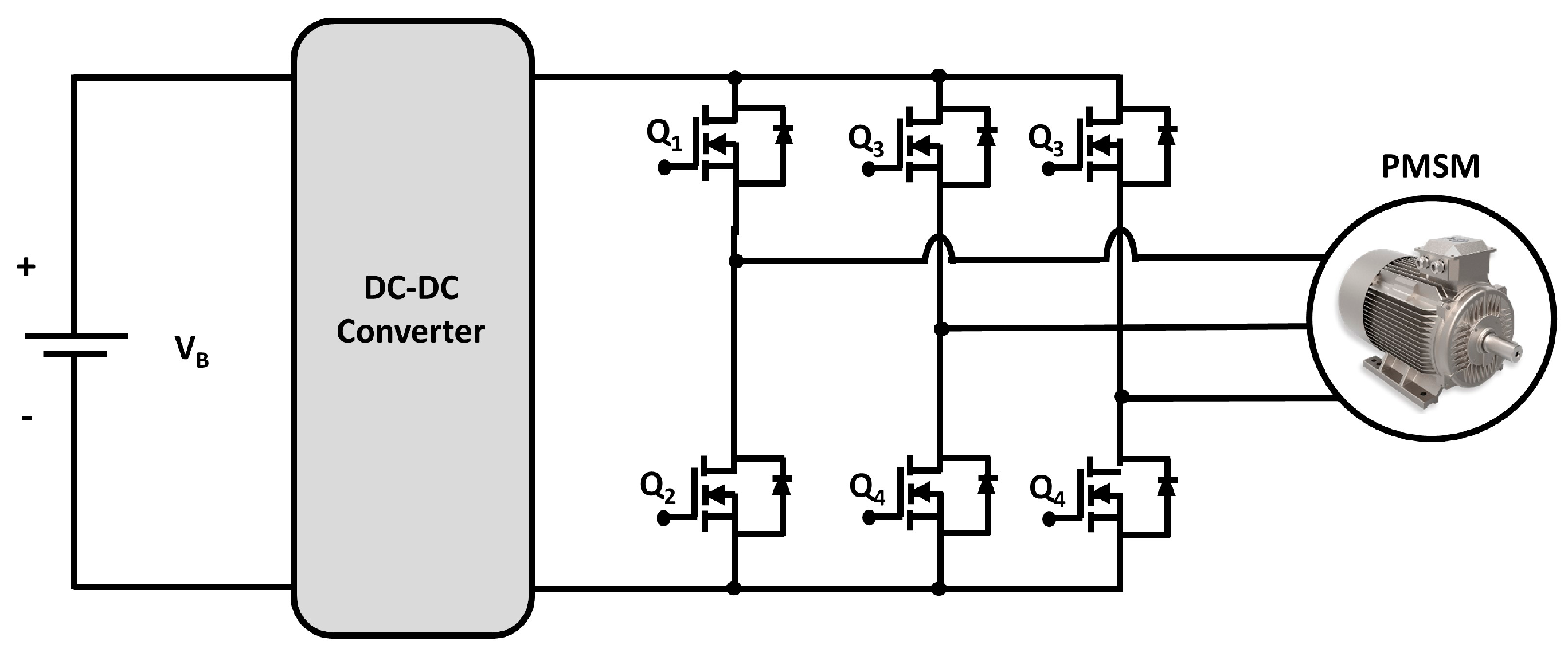
In the electric vehicle (EV) powertrain, all the electric input sources are connected to a HV–DC bus by an individual DC–DC converter, and the output three-phase electric motor (EM), i.e., the main load of the EV, is powered from this HV–DC bus through a three-phase inverter which drives the EM. Here, the voltage level of this HV–DC bus of the EV is around 400–750 V. Moreover, moving the EV via an EM from electric batteries, a DC–DC voltage is required because the batteries’ output voltage is much lower than the required voltage of EM. A traction inverter is needed to drive the EM by converting the DC batteries into variable-frequency AC. However, a disagreement could be made for stepping up the output AC voltage level of the inverter by utilizing a high-voltage transformer instead of a DC–DC converter. This is due to its having several essential advantages, such as reliability, cost-effectiveness, compact size, and lightweight DC–DC converters appear to be excellent candidates for EVs and HEVs powertrains.
1. DC–DC Converter
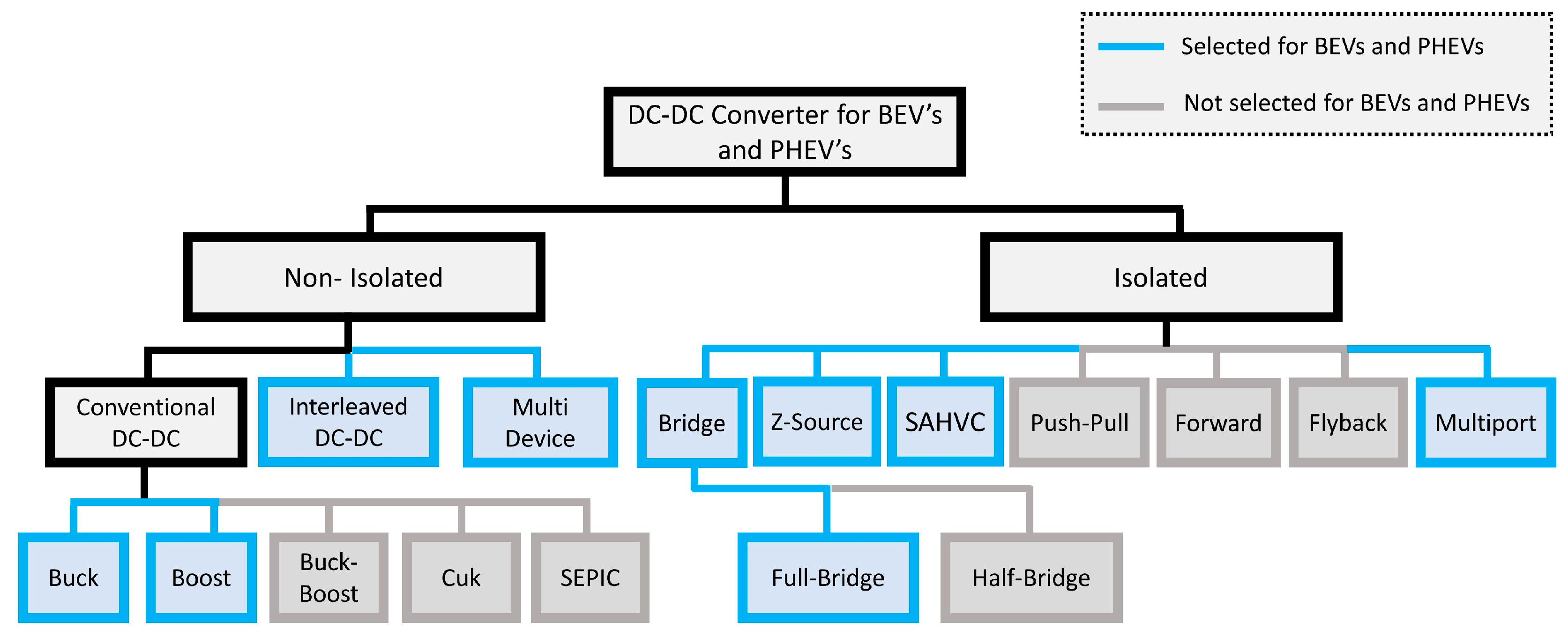
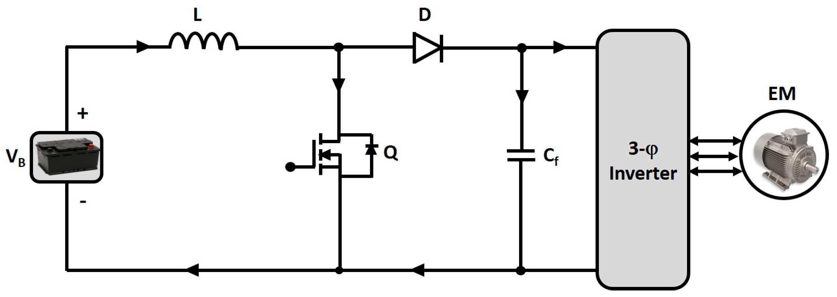
1.1. Conventional Boost DC–DC Converter (BC)
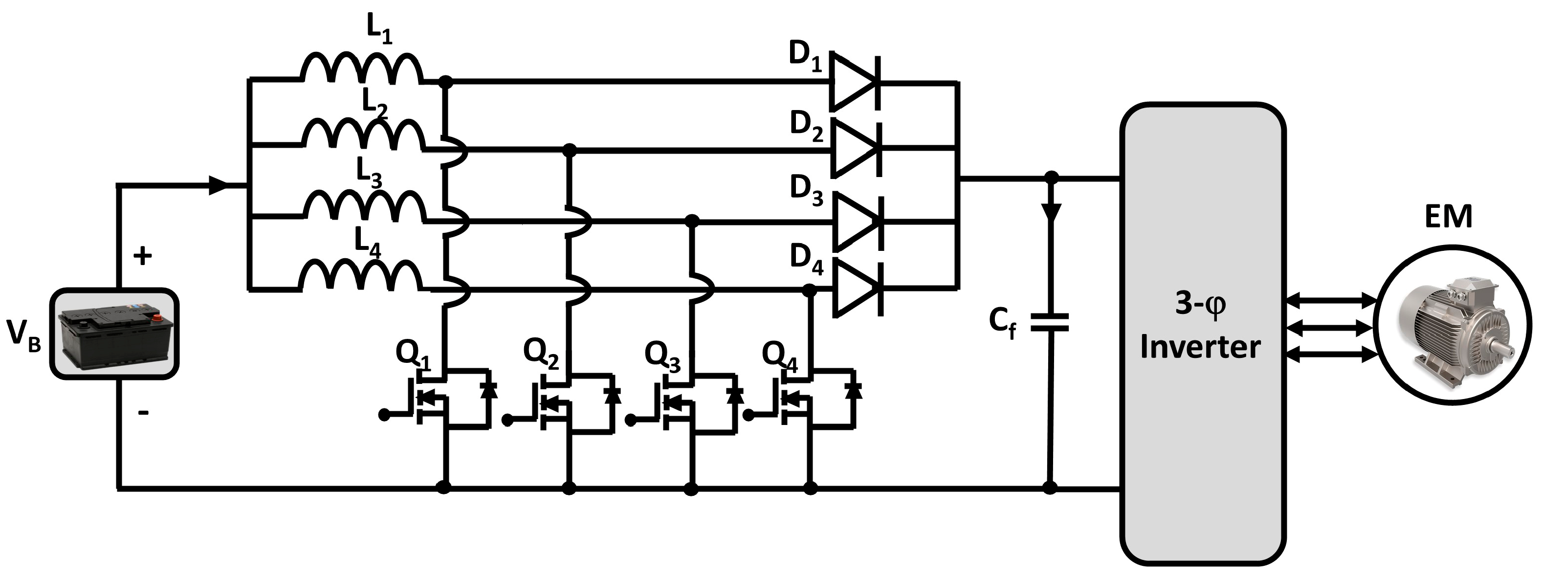
1.2. Interleaved Four-Phase Boost DC–DC Converter (IBC)
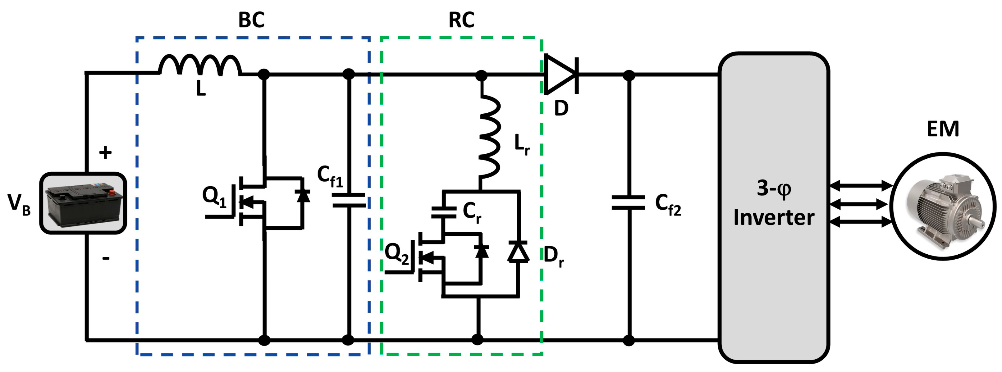
1.3. Boost DC–DC Converter with Resonant Circuit (BCRC)
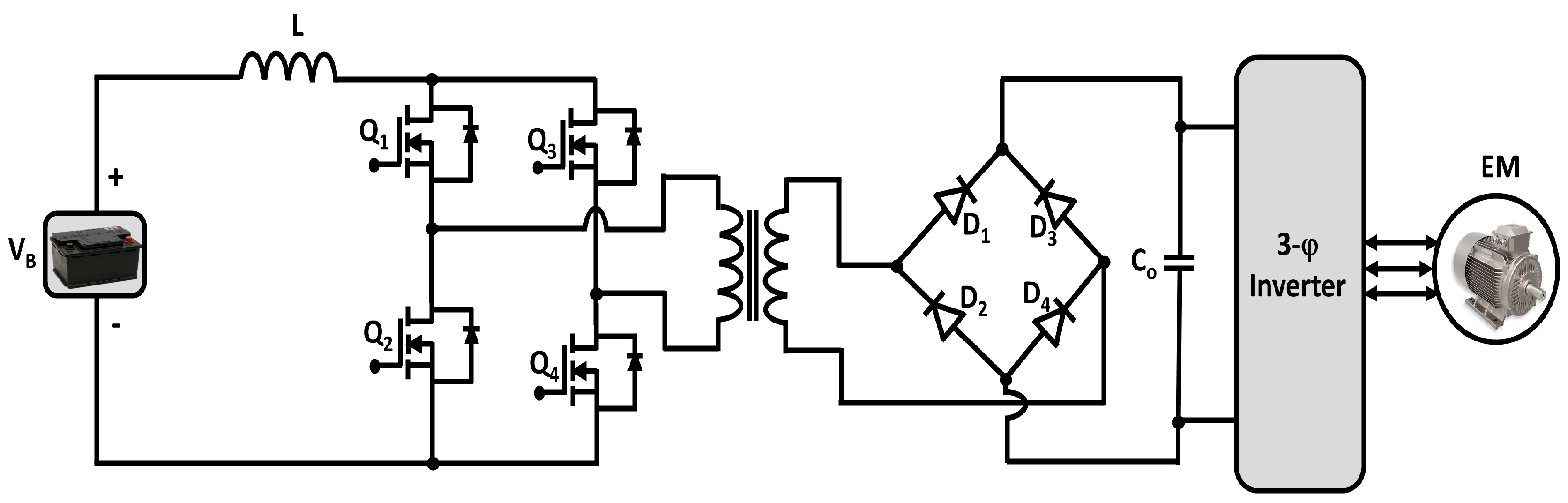
1.4. Full Bridge Boost DC–DC Converter (FBC)
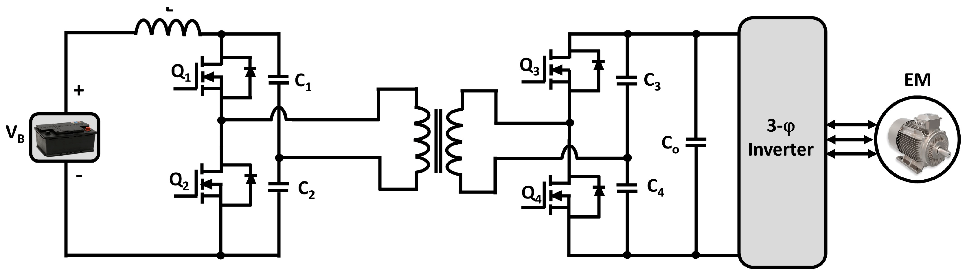
1.5. Isolated ZVS DC–DC Converter (ZVSC)
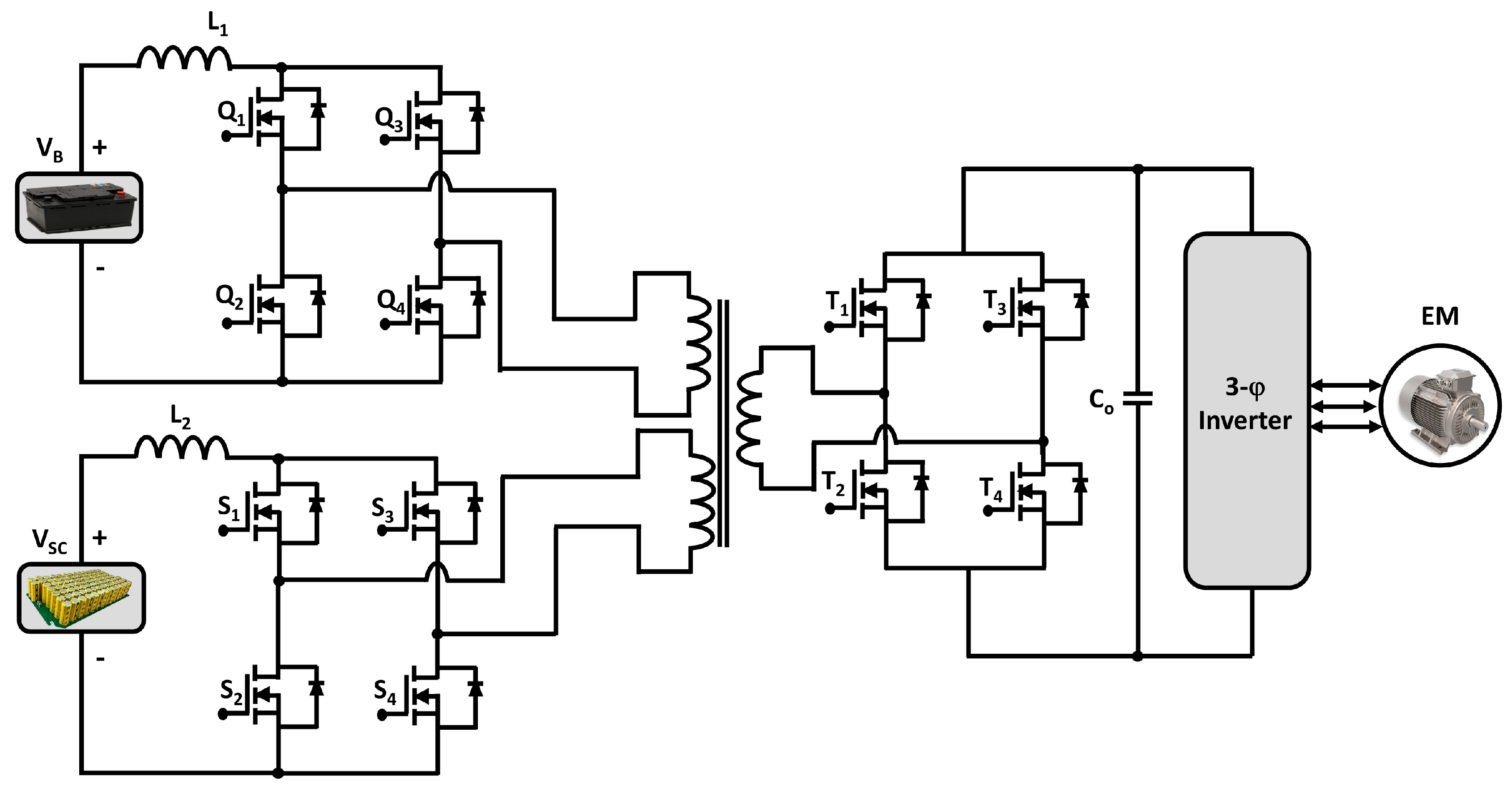
1.6. Isolated Multiport DC–DC Converter (MPC)
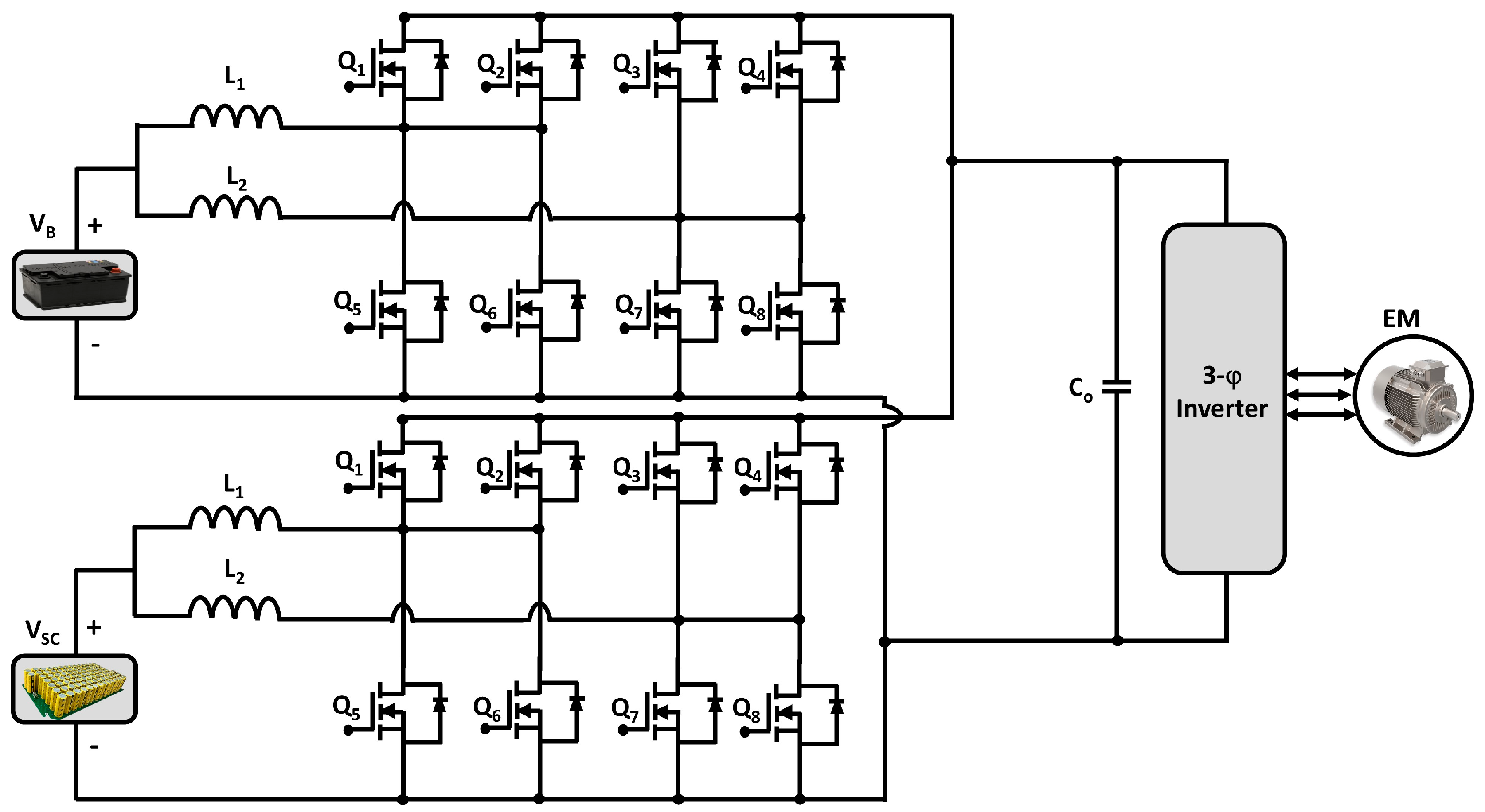
1.7. Multidevice Interleaved DC–DC Bidirectional Converter (MDIBC)
2. Energy Storage
3. Inverter
3.1. Two-Level Inverter (TLI)
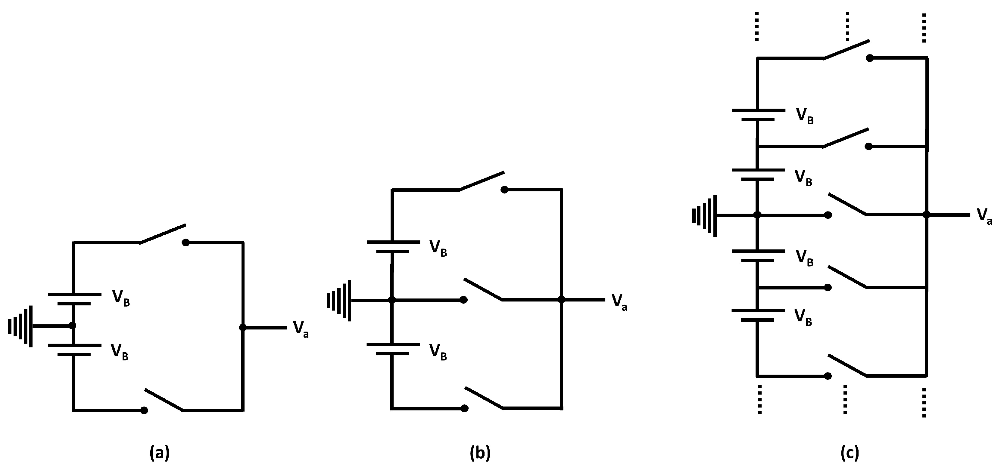
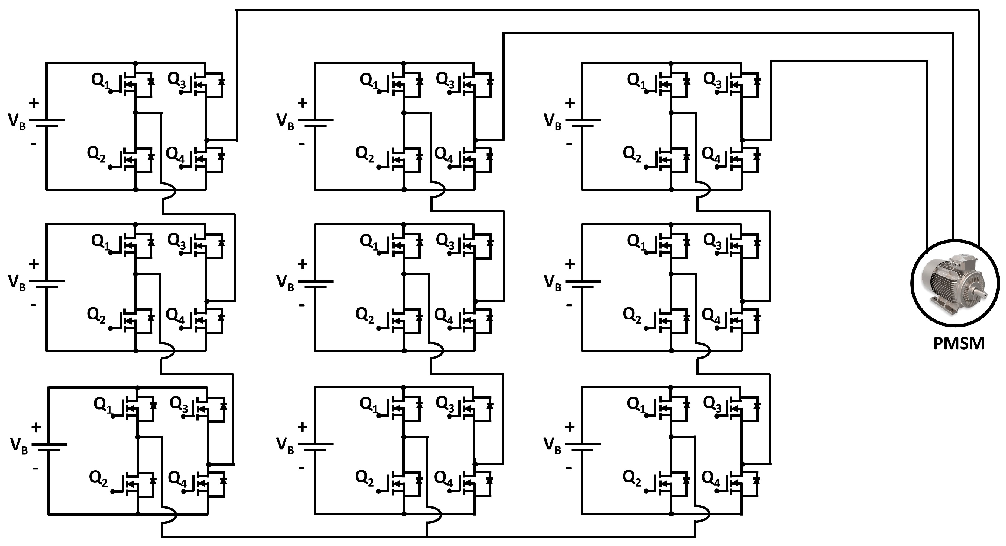
3.2. Multi-Level Inverter (MLI)
4. Motor and Drive
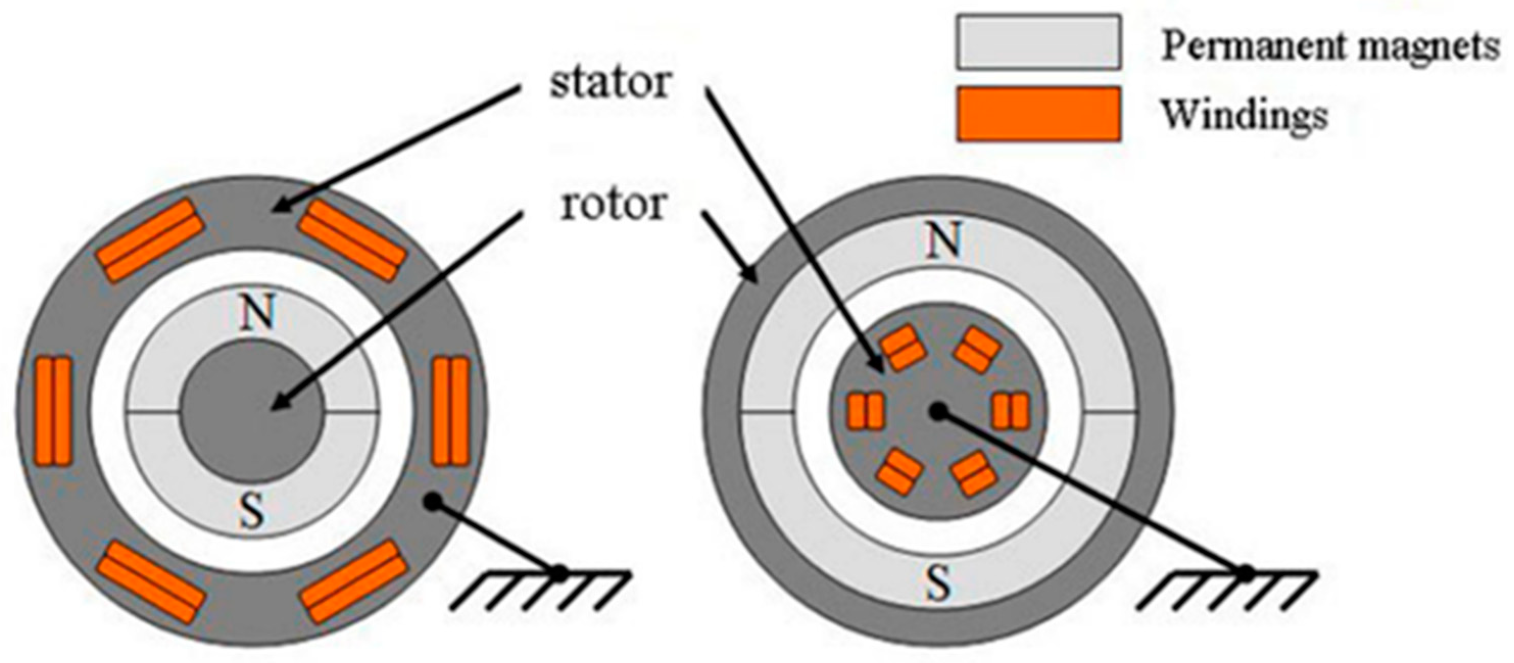
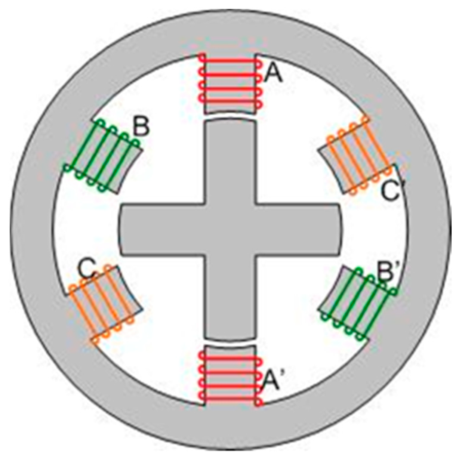
4.1. Traction Motor
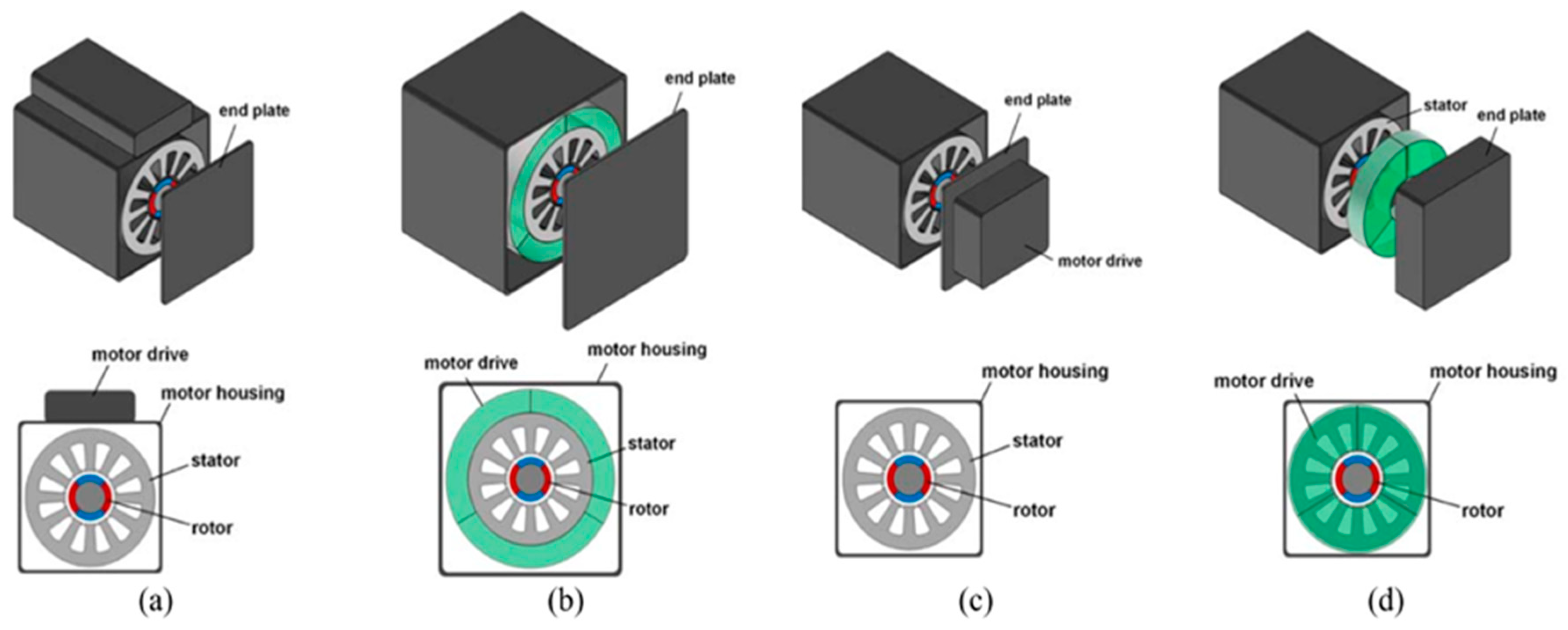
4.2. Integrated Motor Drive
References
- Chakraborty, S.; Vu, H.-N.; Hasan, M.M.; Tran, D.-D.; El Baghdadi, M.; Hegazy, O. DC-DC Converter Topologies for Electric Vehicles, Plug-in Hybrid Electric Vehicles and Fast Charging Stations: State of the Art and Future Trends. Energies 2019, 12, 1569.
- Forouzesh, M.; Siwakoti, Y.P.; Gorji, S.A.; Blaabjerg, F.; Lehman, B. Step-Up DC-DC converters: A comprehensive review of voltage-boosting techniques, topologies, and applications. IEEE Trans. Power Electron. 2017, 32, 9143–9178.
- Rashid, M.H. Power Electronics Handbook; Butterworth-Heinemann: Oxford, UK, 2017.
- Rashid, M.H. Power Electronics: Circuits, Devices, and Applications; Pearson Prentice Hall: Upper Saddle River, NJ, USA, 2004.
- Corcau, J.-I.; Dinca, L. Experimental tests regarding the functionality of a DC to DC Boost Converter. In Proceedings of the 2014 International Symposium on Power Electronics, Electrical Drives, Automation and Motion, Ischia, Italy, 18–20 June 2014; pp. 579–582.
- Al Sakka, M.; Van Mierlo, J.; Gualous, H. DC/DC Converters for Electric Vehicles, Electric Vehicles. Electr. Veh. Model. Simul. 2011, 100, 466.
- Kazimierczuk, M.K. Pulse-Width Modulated DC-DC Power Converters; Wiley: Hoboken, NJ, USA, 2008; ISBN 9780470773017.
- Seo, S.-W.; Choi, H.H. Digital Implementation of Fractional Order PID-Type Controller for Boost DC–DC Converter. IEEE Access 2019, 7, 142652–142662.
- Banerjee, S.; Chakrabarty, K. Nonlinear modeling and bifurcations in the boost converter. IEEE Trans. Power Electron. 1998, 13, 252–260.
- Beg, O.A.; Abbas, H.; Johnson, T.T.; Davoudi, A. Model validation of PWM DC-DC converter. IEEE Trans. Ind. Electron. 2017, 64, 7049–7059.
- di Bernardo, M.; Vasca, F. Discrete-time maps for the analysis of bifurcations and chaos in DC/DC converters. IEEE Trans. Circuits Syst. I Regul. Pap. 2000, 47, 130–143.
- Cafagna, D.; Grassi, G. Bifurcation Analysis and Chaotic Behavior in Boost Converters: Experimental Results. Nonlinear Dyn. 2006, 44, 251–262.
- Rajashekara, K. Power conversion and control strategies for fuel cell vehicles. In Proceedings of the IECON’03, 29th Annual Conference of the IEEE Industrial Electronics Society (IEEE Cat. No.03CH37468), Roanoke, VA, USA, 2–6 November 2003; Volume 3, pp. 2865–2870.
- Kong, X.; Choi, L.T.; Khambadkone, A. Analysis and control of isolated current-fed full bridge converter in fuel cell system. In Proceedings of the 30th Annual Conference of IEEE Industrial Electronics Society, Busan, Korea, 2–6 November 2005.
- Dhanasekaran, S.; Kumar, E.S.; Vijaybalaji, R. Different Methods of Control Mode in Switch Mode Power Supply—A Comparison. Int. J. Adv. Res. Electr. Electron. Instrum. Eng. 2014, 3, 6717–6724.
- Yasoda, S.S.K. Optimization and Closed Loop Control of Soft Switched Boost Converter with Flyback Snubber. Int. J. Comput. Appl. 2013, 975, 8887.
- Tan, S.-C.; Lai, Y.M.; Tse, C.K. Indirect Sliding Mode Control of Power Converters Via Double Integral Sliding Surface. IEEE Trans. Power Electron. 2008, 23, 600–611.
- Yazici, I.; Yaylaci, E.K. Fast and robust voltage control of DC–DC boost converter by using fast terminal sliding mode controller. IET Power Electron. 2016, 9, 120–125.
- Cheng, L.; Acuna, P.; Aguilera, R.P.; Jiang, J.; Wei, S.; Fletcher, J.E.; Lu, D.D.C. Model Predictive Control for DC–DC Boost Converters With Reduced-Prediction Horizon and Constant Switching Frequency. IEEE Trans. Power Electron. 2017, 33, 9064–9075.
- Mardani, M.M.; Khooban, M.H.; Masoudian, A.; Dragicevic, T. Model predictive control of DC-DC converters to miti-gate the effects of pulsed power loads in naval DC microgrids. IEEE Trans. Ind. Electron. 2019, 66, 5676–5685.
- Wei, Q.; Wu, B.; Xu, D.; Zargari, N.R. Model Predictive Control of Capacitor Voltage Balancing for Cascaded Modular DC–DC Converters. IEEE Trans. Power Electron. 2016, 32, 752–761.
- Beid, S.E.; Doubabi, S. DSP-based implementation of fuzzy output tracking control for a boost converter. IEEE Trans. Ind. Electron. 2014, 61, 196–206.
- Chung, G.-B.; Kwack, S.-G. Application of fuzzy integral control for output regulation of asymmetric half-bridge DC/DC converter with current doubler rectifier. J. Power Electron. 2007, 7, 238–245.
- Guo, L.; Hung, J.Y.; Nelms, R.M. Evaluation of DSP-based PID and fuzzy controllers for DC–DC converters. IEEE Trans. Ind. Electron. 2009, 56, 2237–2248.
- Bouarroudj, N.; Boukhetala, D.; Benlahbib, B.; Batoun, B. Sliding model control based on fractional order calculus for DC-DC converters. Int. J. Math. Model. Comput. 2015, 5, 319–333.
- Kumar, J.; Kumar, V.; Rana, K.P.S. A fractional order fuzzy PDCI controller for three-link electrically driven rigid ro-botic manipulator system. J. Intell. Fuzzy Syst. 2018, 35, 5287–5299.
- Shah, P.; Agashe, S. Review of fractional PID controller. Mechatronics 2016, 38, 29–41.
- Faraj, K.S.; Hussein, J.F. Analysis and Comparison of DC-DC Boost Converter and Interleaved DC-DC Boost Converter. Int. J. Eng. Technol. 2020, 38, 622–635.
- Chakraborty, S.; Hasan, M.M.; Abdur Razzak, M. Transformer-less single-phase grid-tie photovoltaic inverter topologies for residential application with various filter circuits. Renew. Sustain. Energy Rev. 2017, 72, 1152–1166.
- Kolli, A.; Gaillard, A.; De Bernardinis, A.; Bethoux, O.; Hissel, D.; Khatir, Z. A review on DC/DC converter architectures for power fuel cell applications. Energy Convers. Manag. 2015, 105, 716–730.
- Zhang, H.; Ma, R.; Han, C.; Xie, R.; Liang, B.; Li, Y. Advanced Control Design of Interleaved Boost Converter for Fuel Cell Applications. In Proceedings of the IECON 2020 The 46th Annual Conference of the IEEE Industrial Electronics Society, Singapore, 18–21 October 2020; pp. 5000–5005.
- Xie, Y.; Ghaemi, R.; Sun, J.; Freudenberg, J.S. Model Predictive Control for a Full Bridge DC/DC Converter. IEEE Trans. Control. Syst. Technol. 2011, 20, 164–172.
- Xu, Q.; Jiang, W.; Blaabjerg, F.; Zhang, C.; Zhang, X.; Fernando, T. Backstepping Control for Large Signal Stability of High Boost Ratio Interleaved Converter Interfaced DC Microgrids With Constant Power Loads. IEEE Trans. Power Electron. 2019, 35, 5397–5407.
- Saadi, R.; Bahri, M.; Ayad, M.Y.; Becherif, M.; Kraa, O.; Aboubou, A. Implementation and dual loop control of two phases interleaved boost converter for fuel cell applications. In Proceedings of the 3rd International Symposium on Environmental Friendly Energies and Applications (EFEA), Paris, France, 19–21 November 2014; pp. 1–7.
- Giral, R.; Martinez-Salamero, L.; Leyva, R.; Maixe, J. Sliding-mode control of interleaved boost converters. IEEE Trans. Circuits Syst. I: Fundam. Theory Appl. 2000, 47, 1330–1339.
- Cid-Pastor, A.; Giral, R.; Calvente, J.; Utkin, V.I.; Martinez-Salamero, L. Interleaved Converters Based on Sliding-Mode Control in a Ring Configuration. IEEE Trans. Circuits Syst. I Regul. Pap. 2011, 58, 2566–2577.
- Han, J. From PID to Active Disturbance Rejection Control. IEEE Trans. Ind. Electron. 2009, 56, 900–906.
- Chang, X.; Li, Y.; Zhang, W.; Wang, N.; Xue, W. Active Disturbance Rejection Control for a Flywheel Energy Storage System. IEEE Trans. Ind. Electron. 2015, 62, 991–1001.
- Ma, R.; Xu, L.; Xie, R.; Zhao, D.; Huangfu, Y.; Gao, F. Advanced Robustness Control of DC–DC Converter for Proton Ex-change Membrane Fuel Cell Applications. IEEE Trans. Ind. Appl. 2019, 55, 6389–6400.
- Varshney, A.; Kumar, R.; Kuanr, D.; Gupta, M. Soft-Switched Boost DC-DC Converter System for Electric Vehicles Using an Auxiliary Resonant Circuit. Inter. J. Emerg. Technol. Adv. Eng. 2014, 4, 845–850.
- Lin, B.-R.; Chao, C.-H. Soft-Switching Converter with Two Series Half-Bridge Legs to Reduce Voltage Stress of Active Switches. IEEE Trans. Ind. Electron. 2012, 60, 2214–2224.
- Zhang, X.; Bai, H.; Zhou, X. Soft switching DC-DC converter control using FBLSMC and frequency modulation in HESS based electric vehicle. In Proceedings of the 2016 IEEE 8th International Power Electronics and Motion Control Conference (IPEMC-ECCE Asia), Hefei, China, 22–26 May 2016; pp. 2209–2213.
- Song, I.; Jung, D.; Ji, Y.; Choi, S.; Jung, Y.; Won, C. A Soft Switching Boost Converter using an Auxiliary Resonant Circuit for a PV System. In Proceedings of the 2016 IEEE 8th International Power Electronics and Motion Control Conference (IPEMC-ECCE Asia), Hefei, China, 22–26 May 2016; pp. 2838–2843.
- Sreelakshmi, S.; Mohan Krishna, S.; Deepa, K. Bidirectional Converter Using Fuzzy for Battery Charging of Electric Vehicle. In Proceedings of the IEEE Transportation Electrification Conference (ITEC-India), Bengaluru, India, 17–19 December 2019; pp. 1–6.
- Veerachary, M. Digital controller design for fourth-order soft-switching boost converte. In Proceedings of the IEEE 7th International Conference on Industrial and Information Systems, Chennai, India, 6–9 August 2012; pp. 1–5.
- Veerachary, M.; Sekhar, R. Digital voltage-mode controller design for high gain soft-switching boost converter. In Proceedings of the 2010 Joint International Conference on Power Electronics, Drives and Energy Systems & 2010 Power India, New Delhi, India, 20–23 December 2010; pp. 1–5.
- Mummadi, V. Design of robust digital PID controller for H-bridge softswitching boost converter. IEEE Trans. Ind. Electron. 2011, 58, 2883–2897.
- Ramachandran, R.; Nymand, M. Loss Modelling and Experimental Verification of A 98.8% Efficiency Bidirectional Isolated DC-DC Converter. E3S Web Conf. 2017, 16, 18003.
- Averberg, A.; Mertens, A. Analysis of a Voltage-fed Full Bridge DC-DC Converter in Fuel Cell Systems. In Proceedings of the 2007 IEEE Power Electronics Specialists Conference, Orlando, FL, USA, 17–21 June 2007; pp. 286–292.
- Saeed, J.; Hasan, A. Control-oriented discrete-time large-signal model of phase-shift full-bridge DC–DC converter. Electr. Eng. 2017, 100, 1431–1439.
- Kim, B.-S.; Kim, H.-J.; Jin, C.; Huh, D.-Y. A digital controlled DC-DC converter for electric vehicle applications. In Proceedings of the 2011 International Conference on Electrical Machines and Systems, Beijing, China, 20–23 August 2011; pp. 1–5.
- Taeed, F.; Nymand, M. Modeling and control of isolated full bridge boost DC-DC converter implemented in FPGA. In Proceedings of the 2013 IEEE 10th International Conference on Power Electronics and Drive Systems (PEDS), Kitakyushu, Japan, 22–25 April 2013; pp. 119–124.
- Madhavi, S.V.; Das, G.T.R. Comparative Study of Controllers for an Isolated Full Bridge Boost Converter To-pology in Fuel Cell Applications. Int. J. Power Electron. Drive Syst. 2018, 9, 1644–1656.
- Peng, F.; Li, H.; Su, G.-J.; Lawler, J. A New ZVS Bidirectional DC–DC Converter for Fuel Cell and Battery Application. IEEE Trans. Power Electron. 2004, 19, 54–65.
- Bronstein, S.; Ben-Yaakov, S. Design considerations for achieving ZVS in a half bridge inverter that drives a piezoelectric transformer with no series inductor. In Proceedings of the IEEE Annual Power Electronics Specialists Conference, Cairns, Australia, 23–27 June 2002; IEEE Computer Society: Washington, DC, USA; pp. 585–590.
- Pahlevaninezhad, M.; Das, P.; Drobnik, J.; Jain, P.K.; Bakhshai, A. A Novel ZVZCS Full-Bridge DC/DC Converter Used for Electric Vehicles. IEEE Trans. Power Electron. 2012, 27, 2752–2769.
- Jeon, S.-J.; Cho, G.-H. A zero-voltage and zero-current switching full bridge DC-DC converter with transformer isolation. IEEE Trans. Power Electron. 2001, 16, 573–580.
- Cho, J.-G.; Baek, J.-W.; Jeong, C.-Y.; Rim, G.-H. Novel zero-voltage and zero-current-switching full-bridge PWM converter using a simple auxiliary circuit. IEEE Trans. Ind. Appl. 1999, 35, 15–20.
- Hamada, S.; Gamage, L.; Morimoto, T.; Nakaoka, M. A novel zero-voltage and zero-current soft-switching PWM DC-DC converter with reduced conduction losses. IEEE Trans. Power Electron. 2002, 2, 741–747.
- Kim, J.; Song, H.; Nam, K. Asymmetric Duty Control of a Dual-Half-Bridge DC/DC Converter for Single-Phase Distrib-uted Generators. IEEE Trans. Power Electron. 2011, 26, 973–982.
- Miftakhutdinov, R.; Nemchinov, A.; Meleshin, V.; Fraidlin, S. Modified asymmetrical ZVS half-bridge DC-DC converter. In Proceedings of the APEC’99. Fourteenth Annual Applied Power Electronics Conference and Exposition. 1999 Conference Proceedings (Cat. No. 99CH36285), Dallas, TX, USA, 14–18 March 1999; Volume 1, pp. 567–574.
- Chen, W.; Xu, P.; Lee, F. The optimization of asymmetric half bridge converter. In Proceedings of the APEC 2001. Sixteenth Annual IEEE Applied Power Electronics Conference and Exposition (Cat. No. 01CH37181), Anaheim, CA, USA, 4–8 March 2002.
- Mao, H.; Abu-Qahouq, J.; Luo, S.; Batarseh, I. Zero-voltage-switching half-bridge DC-DC converter with modi-fied PWM control method. IEEE Trans. Power Electron. 2004, 19, 947–958.
- Mao, H.; Abu-Qahouq, J.; Luo, S.; Batarseh, I. New zero-voltage-switching half-bridge DC-DC converter and PWM control method. In Proceedings of the Eighteenth Annual IEEE Applied Power Electronics Conference and Exposition, Miami Beach, FL, USA, 9–13 February 2004.
- Xie, M.; Huangfu, Y.; Zhang, Q.; Li, Q.; Zhao, D.; Liu, Y. Small Signal Analysis and Control Design of Snubberless Natu-rally Clamped ZCS/ZVS Current-Fed Half-Bridge DC/DC Converter for EV. In Proceedings of the IECON 2018—44th Annual Conference of the IEEE Industrial Electronics Society, Washington, DC, USA, 21–23 October 2018; pp. 4998–5004.
- Zhang, N.; Sutanto, D.; Muttaqi, K.M. A review of topologies of three-port DC–DC converters for the integration of renew-able energy and energy storage system. Renew. Sustain. Energy Rev. 2016, 56, 388–401.
- Al-chlaihawi, S.J.M. Multiport Converter in Electrical Vehicles—A Review. Int. J. Sci. Res. Publ. 2016, 6, 378–382.
- Zhao, C.; Round, S.D.; Kolar, J.W. An Isolated Three-Port Bidirectional DC-DC Converter with Decoupled Power Flow Management. IEEE Trans. Power Electron. 2008, 23, 2443–2453.
- Zeng, J.; Qiao, W.; Qu, L.; Jiao, Y. An Isolated Multiport DC/DC Converter for Simultaneous Power Management of Multi-ple Different Renewable Energy Sources. IEEE J. Emerg. Sel. Top. Power Electron. 2014, 2, 70–78.
- Li, W.; Xiao, J.; Zhao, Y.; He, X. PWM Plus Phase Angle Shift (PPAS) Control Scheme for Combined Multiport DC/DC Converters. IEEE Trans. Power Electron. 2011, 27, 1479–1489.
- Saeed, L.; Khan, M.Y.A.; Khan, S.H.; Azhar, M. Design and Control for a Multiport DC-DC Boost Converter with Battery Backup for Microgrid. In Proceedings of the 2019 International Conference on Engineering and Emerging Technologies (ICEET), Lahore, Pakistan, 21–22 February 2019; pp. 1–6.
- Rashidi, M.; Altin, N.N.; Ozdemir, S.S.; Bani-Ahmed, A.; Nasiri, A. Design and Development of a High-Frequency Mul-tiport Solid-State Transformer with Decoupled Control Scheme. IEEE Trans. Ind. Appl. 2019, 55, 7515–7526.
- Hegazy, O.; Barrero, R.; Van Mierlo, J.; Lataire, P.; Omar, N.; Coosemans, T. An Advanced Power Electronics Interface for Electric Vehicles Applications. IEEE Trans. Power Electron. 2013, 28, 5508–5521.
- Hegazy, O.; Van Mierlo, J.; Lataire, P. Analysis, modeling, and implementation of a multidevice interleaved DC/DC con-verter for fuel cell hybrid electric vehicles. IEEE Trans. Power Electron. 2012, 27, 4445–4458.
- Farakhor, A. Non-isolated multi-input–single-output DC/DC converter for photovoltaic power generation systems. IET Power Electron. 2014, 7, 2806–2816.
- Wu, H.; Xing, Y.; Xia, Y.; Sun, K. A family of non-isolated three-port converters for stand-alone renewable power system. In Proceedings of the IECON 2011—37th Annual Conference of the IEEE Industrial Electronics Society, Melbourne, VIC, Australia, 7–10 November 2011; pp. 1030–1035.
- Wu, H.; Sun, K.; Ding, S.; Xing, Y. Topology Derivation of Nonisolated Three-Port DC–DC Converters from DIC and DOC. IEEE Trans. Power Electron. 2012, 28, 3297–3307.
- Nahavandi, A.; Hagh, M.T.; Sharifian, M.B.B.; Danyali, S. A Nonisolated Multiinput Multioutput DC–DC Boost Converter for Electric Vehicle Applications. IEEE Trans. Power Electron. 2014, 30, 1818–1835.
- Samosir, A.; Taufiq; Shafie, A.; Yatim, A. Simulation and Implementation of Interleaved boost dc-dc converter for fuel cell application. Int. J. Power Electron. Drive Syst. 2011, 1, 168–174.
- Ho, C.N.-M.; Breuninger, H.; Pettersson, S.; Escobar, G.; Serpa, L.A.; Coccia, A. Practical Design and Implementation Proce-dure of an Interleaved Boost Converter Using SiC Diodes for PV Applications. Power Electron. IEEE Trans. 2012, 27, 2835–2845.
- Ayoubi, Y.; Elsied, M.; Oukaour, A.; Chaoui, H.; Slamani, Y.; Gualous, H. Four-phase interleaved DC/DC boost converter in-terfaces for super-capacitors in electric vehicle application based on advanced sliding mode control design. Electr. Power Syst. Res. 2016, 134, 186–196.
- Hegazy, O.; Van Mierlo, J.; Lataire, P. Analysis, control and comparison of DC/DC boost converter topologies for fuel cell hybrid electric vehicle applications. In Proceedings of the 2011 14th European Conference on Power Electronics and Applications, Birmingham, UK, 30 August–1 September 2011.
- Smith, N.; McCann, R. Analysis and simulation of a multiple input interleaved boost converter for renewable energy applications. In Proceedings of the 2014 IEEE 36th International Telecommunications Energy Conference (INTELEC), Vancouver, BC, Canada, 28 September–2 October 2014; pp. 1–7.
- Veerachary, M.; Senjyu, T.; Uezato, K. Neural-network-based maximum-power-point tracking of coupled-inductor in-terleaved-boost-converter-supplied PV system using fuzzy controller. IEEE Trans. Ind. Electron. 2003, 50, 749–758.
- So, W.; Tse, C.; Lee, Y. A fuzzy controller for DC-DC converters. IEEE Trans. Power Electron. 2002, 1, 315–320.
- Gupta, T.; Boudreaux, R.; Nelms, R.; Hung, J. Implementation of a fuzzy controller for DC-DC converters using an inexpensive 8-b microcontroller. IEEE Trans. Ind. Electron. 1997, 44, 661–669.
- Mattavelli, P.; Rossetto, L.; Spiazzi, G.; Tenti, P. General-purpose fuzzy controller for DC/DC converters. IEEE Trans. Power Electron. 2002, 12, 79–86.
- Wu, T.-F.; Chang, C.-H.; Chen, Y.-H. A fuzzy-logic-controlled single-stage converter for PV-powered lighting system applications. IEEE Trans. Ind. Electron. 2000, 47, 287–296.
- Josefsson, O. Energy Efficiency Comparison between Two-Level and Multilevel Inverters for Electric Vehicle Applications; 27753488; Chalmers Tekniska Hogskola (Sweden) ProQuest Dissertations Publishing: Gothenburg, Sweden, 2013.
- Josefsson, O. Investigation of a Multilevel Inverter for Electric Vehicle Applications; Chalmers Tekniska Hogskola: Gothenburg, Sweden, 2015.
- Capasso, C.; Veneri, O. Experimental analysis on the performance of lithium based batteries for road full electric and hybrid vehicles. Appl. Energy 2014, 136, 921–930.
- Hannan, A.; Hoque, M.; Hussain, A.; Yusof, Y.; Ker, P.J. State-of-the-art and energy management system of lithium-ion batteries in electric vehicle applications: Issues and recommendations. IEEE Access 2018, 6, 19362–19378.
- Dunn, B.; Kamath, H.; Tarascon, J.-M. Electrical Energy Storage for the Grid: A Battery of Choices. Science 2011, 334, 928–935.
- Chen, W.; Liang, J.; Yang, Z.; Li, G. A Review of Lithium-Ion Battery for Electric Vehicle Applications and Beyond. Energy Procedia 2019, 158, 4363–4368.
- Manzetti, S.; Mariasiu, F. Electric vehicle battery technologies: From present state to future systems. Renew. Sustain. Energy Rev. 2015, 51, 1004–1012.
- Yi, T.-F.; Mei, J.; Zhu, Y.-R. Key strategies for enhancing the cycling stability and rate capacity of LiNi0.5Mn1.5O4 as high-voltage cathode materials for high power lithium-ion batteries. J. Power Sources 2016, 316, 85–105.
- Marongiu, A.; Nussbaum, F.; Waag, W.; Garmendia, M.; Sauer, D.U. Comprehensive study of the influence of aging on the hysteresis behavior of a lithium iron phosphate cathode-based lithium-ion battery—An experimental investigation of the hysteresis. Appl. Energy 2016, 171, 629–645.
- Park, M.; Shin, D.-S.; Ryu, J.; Choi, M.; Park, N.; Hong, S.Y.; Cho, J. Organic-Catholyte-Containing Flexible Rechargeable Lithium Batteries. Adv. Mater. 2015, 27, 5141–5146.
- Hoque, M.M.; Hannan, M.; Mohamed, A. Model development of charge equalization controller for lithium-ion battery. Adv. Sci. Lett. 2017, 23, 5255–5259.
- Tomaszewska, A.; Chu, Z.; Feng, X.; O’kane, S.; Liu, X.; Chen, J.; Ji, C.; Endler, E.; Li, R.; Liu, L.; et al. Lithium-ion battery fast charging: A review. eTransportation 2019, 1, 100011.
- Ronanki, D.; Kelkar, A.; Williamson, S.S. Extreme Fast Charging Technology—Prospects to Enhance Sustainable Electric Transportation. Energies 2019, 12, 3721.
- Meintz, A.; Zhang, J.; Vijayagopal, R.; Kreutzer, C.; Ahmed, S.; Bloom, I.; Burnham, A.; Carlson, R.B.; Dias, F.; Tanim, T.; et al. Enabling fast charging-vehicle considerations. J. Power Sour. 2017, 367, 216–227.
- Poorfakhraei, A.; Narimani, M.; Emadi, A. A Review of Multilevel Inverter Topologies in Electric Vehicles: Current Status and Future Trends. IEEE Open J. Power Electron. 2021, 2, 155–170.
- de Santiago, J.; Bernhoff, H.; Ekergård, B.; Eriksson, S.; Ferhatovic, S.; Waters, R.; Leijon, M. Electrical Motor Drivelines in Commercial AllElectric Vehicles: A Review. IEEE Trans. Veh. Technol. 2012, 61, 475–484.
- Bubert, A.; Oberdieck, K.; Xu, H.; De Doncker, R.W. Experimental Validation of Design Concepts for Future EV-Traction Inverters. In Proceedings of the 2018 IEEE Transportation Electrification Conference and Expo (ITEC), Long Beach, CA, USA, 13–15 June 2018; pp. 795–802.
- Wikipedia. Power Semiconductor Device. 2012. Available online: http://en.wikipedia.org/wiki/Power_semiconductor_device (accessed on 20 June 2020).
- Vijeh, M.; Rezanejad, M.; Samadaei, E.; Bertilsson, K. A general review of multilevel inverters based on main submodules: Structural point of view. IEEE Trans. Power Electron. 2019, 34, 9479–9502.
- Vemuganti, H.P.; Sreenivasarao, D.; Ganjikunta, S.K.; Suryawanshi, H.M.; Abu-Rub, H. A Survey on Reduced Switch Count Multilevel Inverters. IEEE Open J. Ind. Electron. Soc. 2021, 2, 80–111.
- Curkovic, M.; Jezernik, K.; Horvat, R. FPGA-Based Predictive Sliding Mode Controller of a Three-Phase Inverter. IEEE Trans. Ind. Electron. 2012, 60, 637–644.
- Rafin, S.M.S.H.; Lipo, T.A.; Kwon, B. A novel topology for a voltage source inverter with reduced transistor count and utilizing naturally commutated thyristors with simple commutation. In Proceedings of the 2014 International Symposium on Power Electronics, Electrical Drives, Automation and Motion, Ischia, Italy, 18–20 June 2014; pp. 643–648.
- Kumar, K.V.; Michael, P.A.; John, J.P.; Kumar, S.S. Simulation and comparison of SPWM and SVPWM control for three phase inverter. ARPN J. Eng. Appl. Sci. 2010, 5, 61–74.
- Kazmierkowski, M.P.; Krishnan, R.; Blaabjerg, F.; Irwin, J.D. Control in Power Electronics: Selected Problems; Academic: New York, NY, USA, 2002.
- Kennel, R.; Linder, A.; Linke, M. Generalized predictive control (GPC)—Ready for use in drive applications? In Proceedings of the 2001 IEEE 32nd Annual Power Electronics Specialists Conference (IEEE Cat. No. 01CH37230), Vancouver, BC, Canada, 17–21 June 2001; Volume 4, pp. 1839–1844.
- Bhattacharjee, T.; Jamil, M.; Jana, A. Design of SPWM based three phase inverter model. In Proceedings of the IEEE 2018 Technologies for Smart-City Energy Security and Power (ICSESP), Bhubaneswar, India, 28–30 March 2018; pp. 1–6.
- YingYing, J.; XuDong, W.; LiangLiang, M.; ShuCai, Y.; HaiXing, Z. Application and Simulation of SVPWM in three phase inverter. In Proceedings of the 2011 IEEE 6th International Forum on Strategic Technology, Harbin, China, 22–24 August 2011; Volume 1, pp. 541–544.
- Rivera, M.; Morales, F.; Baier, C.; Munoz, J.; Tarisciotti, L.; Zanchetta, P.; Wheeler, P. A modulated model predictive con-trol scheme for a two-level voltage source inverter. In Proceedings of the 2015 IEEE International Conference on Industrial Technology (ICIT), Seville, Spain, 17–19 March 2015; pp. 2224–2229.
- Leon, J.I.; Vazquez, S.; Franquelo, L.G. Multilevel Converters: Control and Modulation Techniques for Their Operation and Industrial Applications. Proc. IEEE 2017, 105, 2066–2081.
- Ronanki, D.; Williamson, S.S. Modular multilevel converters for transportation electrification: Challenges and oppor-tunities. IEEE Trans. Transp. Electrific. 2018, 4, 399–407.
- Trabelsi, M.; Vahedi, H.; Abu-Rub, H. Review on Single-DC-Source Multilevel Inverters: Topologies, Challenges, Industrial Applications, and Recommendations. IEEE Open J. Ind. Electron. Soc. 2021, 2, 112–127.
- Hinago, Y.; Koizumi, H. A single-phase multilevel inverter using switched series/parallel dc voltage sources. IEEE Trans. Ind. Electron. 2010, 57, 2643–2650.
- Gupta, K.K.; Jain, S. A Novel Multilevel Inverter Based on Switched DC Sources. IEEE Trans. Ind. Electron. 2013, 61, 3269–3278.
- Tolbert, L.M.; Peng, F.Z.; Habetler, T.G. Multilevel inverters for electric vehicle applications. In Proceedings of the Power Electronics in Transportation (Cat. No. 98TH8349), Gdansk, Poland, 27–30 June 2011; pp. 79–84.
- Nabae, A.; Takahashi, I.; Akagi, H. A new neutral-pointclamped PWM inverter. IEEETrans. Ind. Appl. 1981, IA-17, 518–523.
- Ounejjar, Y.; Al-Haddad, K.; Gregoire, L.-A. Packed U cells multilevel converter topology: Theoretical study and ex-perimental validation. IEEE Trans. Ind. Electron. 2011, 58, 1294–1306.
- Escalante, M.; Vannier, J.-C.; Arzande, A. Flying capacitor multilevel inverters and DTC motor drive applications. IEEE Trans. Ind. Electron. 2002, 49, 809–815.
- Rafin, S.M.S.H.; Lipo, T.A. A novel cascaded two transistor H-bridge multilevel voltage source converter topology. In Proceedings of the 2015 Intl Aegean Conference on Electrical Machines & Power Electronics (ACEMP), 2015 Intl Conference on Optimization of Electrical & Electronic Equipment (OPTIM) & 2015 Intl Symposium on Advanced Electromechanical Motion Systems (ELECTROMOTION), Side, Turkey, 2–4 September 2015; pp. 40–45.
- Hasan, N.S.; Rosmin, N.; Osman, D.A.A.; Musta’amal, A.H. Reviews on multilevel converter and modulation techniques. Renew. Sustain. Energy Rev. 2017, 80, 163–174.
- Richardeau, F.; Pham, T.T.L. Reliability Calculation of Multilevel Converters: Theory and Applications. IEEE Trans. Ind. Electron. 2012, 60, 4225–4233.
- Choudhury, A.; Pillay, P. Space Vector Based Capacitor Voltage Balancing for a Three-Level NPC Traction Inverter Drive. IEEE J. Emerg. Sel. Top. Power Electron. 2019, 8, 1276–1286.
- Malarvizhi, M.; Nagarajan, R.; Meenakshi, M.; Banupriya, R. Unipolar Sine Multicarrier SPWM Control Strategies for Seven-Level Cascaded Inverter. Int. J. Emerg. Technol. Eng. Res. 2018, 6, 111–117.
- Gupta, A.K.; Khambadkone, A.M. A Space Vector PWM Scheme for Multilevel Inverters Based on Two-Level Space Vector PWM. IEEE Trans. Ind. Electron. 2006, 53, 1631–1639.
- Colak, I.; Bayindir, R.; Kabalci, E. A modified harmonic mitigation analysis using Third Harmonic Injection PWM in a multilevel inverter control. In Proceedings of the 14th International Power Electronics and Motion Control Conference, Ohrid, Macedonia, 6–8 September 2010; pp. 215–220.
- Rafin, S.M.S.H.; Lipo, T.A.; Kwon, B.I. Performance analysis of the three-transistor voltage source inverter using different PWM techniques. In Proceedings of the 2015 9th International Conference on Power Electronics and ECCE Asia (ICPE-ECCE Asia), Seoul, Korea, 1–5 June 2015.
- Bilgin, B.; Liang, J.; Terzic, M.V.; Dong, J.; Rodriguez, R.; Trickett, E.; Emadi, A. Modeling and Analysis of Electric Motors: State-of-the-Art Review. IEEE Trans. Transp. Electrif. 2019, 5, 602–617.
- Bostanci, E.; Moallem, M.; Parsapour, A.; Fahimi, B. Opportunities and Challenges of Switched Reluctance Motor Drives for Electric Propulsion: A Comparative Study. IEEE Trans. Transp. Electrif. 2017, 3, 58–75.
- Popescu, M.; Foley, I.; Staton, D.A.; Goss, J.E. Multi-Physics Analysis of a High Torque Density Motor for Electric Racing Cars. In Proceedings of the 2015 IEEE Energy Conversion Congress and Exposition (ECCE), Montreal, QC, Canada, 20–24 September 2015; pp. 6537–6544.
- Zhu, Z.Q.; Howe, D. Electrical Machines and Drives for Electric, Hybrid, and Fuel Cell Vehicles. Proc. of the IEEE 2007, 95, 746–765.
- Boldea, I.; Tutelea, L.N.; Parsa, L.; Dorrell, D. Automotive Electric Propulsion Systems with Reduced or No Permanent Magnets: An Overview. IEEE Trans. Ind. Electron. 2014, 61, 5696–5711.
- Yilmaz, M. Limitations/capabilities of electric machine technologies and modeling approaches for electric motor design and analysis in plug-in electric vehicle applications. Renew. Sustain. Energy Rev. 2015, 52, 80–99.
- Dorrell, D.G.; Knight, A.M.; Popescu, M.; Evans, L.; Staton, D.A. Comparison of different motor design drives for hybrid electric vehicles. In Proceedings of the 2010 IEEE Energy Conversion Congress and Exposition, Atlanta, GA, USA, 12–16 September 2010; pp. 3352–3359.
- Zeraoulia, M.; Benbouzid, M.E.H.; Diallo, D. Electric Motor Drive Selection Issues for HEV Propulsion Systems: A Comparative Study. IEEE Trans. Veh. Technol. 2006, 55, 1756–1764.
- Ramarathnam, S.; Mohammed, A.K.; Bilgin, B.; Sathyan, A.; Dadkhah, H.; Emadi, A. A Review of Structural and Thermal Analysis of Traction Motors. IEEE Trans. Transp. Electrif. 2015, 1, 255–265.
- Fessler, R.R. Final report on assessment of motor technologies for traction drives of hybrid and electric vehicles. Oa-Kridge Nat. Lab. Oakridge TN Tech. Rep. 2011, 10, 2018.
- Ehsani, M.; Rahman, K.; Toliyat, H. Propulsion system design of electric and hybrid vehicles. IEEE Trans. Ind. Electron. 1997, 44, 19–27.
- Kamiya, M. Development of Traction Drive Motors for the Toyota Hybrid System. IEEJ Trans. Ind. Appl. 2006, 126, 473–479.
- Momen, F.; Rahman, K.; Son, Y. Electrical propulsion system design of Chevrolet Bolt battery electric vehicle. IEEE Trans. Ind. Appl. 2019, 55, 376–384.
- Iwai, A.; Honjo, S.; Suzumori, H.; Okazawa, T. Development of Traction Motor for New Zero—Emission Vehicle. In Proceedings of the 2018 International Power Electronics Conference (IPEC-Niigata 2018-ECCE Asia), Niigata, Japan, 20–24 May 2018.
- Namiki, K.; Murota, K.; Shorji, M. High Performance Motor and Inverter System for a Newly Developed Electric Vehicle; SAE Technical Paper 2018-01-0461; SAE International: Warrendale, PA, USA, 2018.
- El-Refaie, A.; Jahns, T. Optimal flux weakening in surface PM machines using concentrated windings. In Proceedings of the Conference Record of the 2004 IEEE Industry Applications Conference, 39th IAS Annual Meeting, Seattle, WA, USA, 3–7 October 2004.
- Gan, J.; Chau, K.T.; Chan, C.C.; Jiang, J.Z. A new surface-inset, permanent-magnet, brushless DC motor drive for electric vehicles. IEEE Trans. Magn. 2000, 36, 3810–3818.
- Chau, K.T.; Chan, C.C.; Liu, C. Overview of Permanent-Magnet Brushless Drives for Electric and Hybrid Electric Vehicles. IEEE Trans. Ind. Electron. 2008, 55, 2246–2257.
- Nerg, J.; Rilla, M.; Ruuskanen, V.; Pyrhönen, J.; Ruotsalainen, S. Direct-Driven Interior Magnet Permanent-Magnet Syn-chronous Motors for a Full Electric Sports Car. IEEE Trans. Ind. Electron. 2014, 61, 4286–4294.
- Parsa, L.; Toliyat, H.A. Fault-Tolerant Interior-Permanent-Magnet Machines for Hybrid Electric Vehicle Applications. IEEE Trans. Veh. Technol. 2007, 56, 1546–1552.
- Honda, Y.; Nakamura, T.; Higaki, T.; Takeda, Y. Motor design considerations and test results of an interior permanent magnet synchronous motor for electric vehicles. In Proceedings of the IAS’97. Conference Record of the 1997 IEEE Industry Applications Conference Thirty-Second IAS Annual Meeting, New Orleans, LA, USA, 5–9 October 2002.
- Makni, Z.; Besbes, M.; Marchand, C. Multiphysics design metholodology of permanent-magnet syncrhonous motors. IEEE Trans. Veh. Technol. 2007, 56, 1524–1530.
- Kiyota, K.; Sugimoto, H.; Chiba, A. Comparing Electric Motors: An Analysis Using Four Standard Driving Schedules. IEEE Ind. Appl. Mag. 2014, 20, 12–20.
- Wang, J.; Yuan, X.; Atallah, K. Design Optimization of a Surface-Mounted Permanent-Magnet Motor with Concentrated Windings for Electric Vehicle Applications. IEEE Trans. Veh. Technol. 2012, 62, 1053–1064.
- Lin, J.; Schofield, N.; Emadi, A. External-Rotor Switched Reluctance Motor for an Electric Bicycle. IEEE Trans. Transp. Electrif. 2015, 1, 348–356.
- Gerada, D.; Mebarki, A.; Brown, N.L.; Gerada, C.; Cavagnino, A.; Boglietti, A. High-Speed Electrical Machines: Technolo-gies, Trends, and Developments. IEEE Trans. Ind. Electron. 2014, 61, 2946–2959.
- Rafin, S.M.S.H.; Ali, Q.; Khan, S.; Lipo, T.A. A novel two-layer winding topology for sub-harmonic synchronous machines. Electr. Eng. 2022, 104, 3027–3035.
- Rafin, S.M.S.H.; Ali, Q.; Lipo, T.A. A Novel Sub-Harmonic Synchronous Machine Using Three-Layer Winding Topology. World Electr. Veh. J. 2022, 13, 16.
- Kiyota, K.; Chiba, A. Design of Switched Reluctance Motor Competitive to 60-kW IPMSM in Third-Generation Hybrid Electric Vehicle. IEEE Trans. Ind. Appl. 2012, 48, 2303–2309.
- Throne, D.; Martinez, F.; Marguire, R.; Arens, D. Integrated Motor/Drive Technology with Rockwell Connectivity; Tech. Rep.; Rexroth, Bosch Group: Lohr am Main, Germany; Available online: http://www.cmafh.com/enewsletter/PDFs/IntegratedMotorDrives.pdf (accessed on 20 March 2021).
- März, M.; Schimanek, E.; Billmann, M. Towards an integrated drive for hybrid traction. In Proceedings of the CPES Power Electronic Conference, Blacksburg, VA, USA, 17–20 April 2005; pp. 1–5.
- Zhang, H.; Wang, J. Active Steering Actuator Fault Detection for An Automatically-steered Electric Ground Vehicle. IEEE Trans. Veh. Technol. 2017, 66, 3685–3702.
- Meng, F.; Zhang, H.; Cao, D.; Chen, H. System modeling and pressure control of a clutch actuator for heavy-duty auto-matic transmission systems. IEEE Trans. Veh. Technol. 2016, 65, 4865–4874.
- Sun, W.; Pan, H.; Gao, H. Filter-Based Adaptive Vibration Control for Active Vehicle Suspensions With Electrohydraulic Actuators. IEEE Trans. Veh. Technol. 2015, 65, 4619–4626.
- Martins, I.; Esteves, J.; Marques, G.; da Silva, F.P. Permanent-Magnets Linear Actuators Applicability in Automobile Active Suspensions. IEEE Trans. Veh. Technol. 2006, 55, 86–94.
- Abebe, R.; Vakil, G.; Calzo, G.L.; Cox, T.; Lambert, S.; Johnson, M.; Gerada, C.; Mecrow, B. Integrated motor drives: State of the art and future trends. IET Electr. Power Appl. 2016, 10, 757–771.
- Brown, N.R.; Jahns, T.M.; Lorenz, R.D. Power converter design for an integrated modular motor drive. In Proceedings of the 2007 IEEE Industry Applications Annual Meeting, New Orleans, LA, USA, 23–27 September 2007; pp. 1322–1328.
- Lee, W.; Li, S.; Han, D.; Sarlioglu, B.; Minav, T.A.; Pietola, M. A Review of Integrated Motor Drive and Wide-Bandgap Power Electronics for High-Performance Electro-Hydrostatic Actuators. IEEE Trans. Transp. Electrif. 2018, 4, 684–693.
- Czyz, P.; Reinke, A.; Cichowski, A.; Sleszynski, W. Performance comparison of a 650 V GaN SSFET and CoolMOS. In Proceedings of the 2016 10th International Conference on Compatibility, Power Electronics and Power Engineering (CPE-POWERENG), Bydgoszcz, Poland, 29 June–1 July 2016; pp. 438–443.
- Bertelshofer, T.; Horff, R.; März, A.; Bakran, M.-M. A performance comparison of a 650 V Si IGBT and SiC MOSFET in-verter under automotive conditions. In Proceedings of the PCIM Europe 2016 International Exhibition and Conference for Power Electronics, Intelligent Motion, Renewable Energy and Energy Management, Nuremberg, Germany, 10–12 May 2016; pp. 1–6.
- März, M.; Poech, M.H.; Schimanek, E.; Schletz, A. Mechatronic integration into the hybrid powertrain—The thermal challenge. In Proceedings of the International Conference Automotive Power Electronics (APE), Tegernsee, Germany, 4–6 October 2006; pp. 1–6.
- Wang, J.; Li, Y.; Han, Y. Integrated Modular Motor Drive Design with GaN Power FETs. IEEE Trans. Ind. Appl. 2015, 51, 3198–3207.
- Shea, A.; Jahns, T.M. Hardware integration for an integrated modular motor drive including distributed control. In Proceedings of the 2014 IEEE Energy Conversion Congress and Exposition (ECCE), Pittsburgh, PA, USA, 14–18 September 2014; pp. 4881–4887.

