1. DC–DC Converter
For driving electric vehicles (EVs), a particular voltage level is required; otherwise, the device can be destroyed if the power is more significant than its required operating power or the device won’t be able to run if the power level is deficient. A DC–DC converter is utilized to mitigate the limitation
[1][6].
Generally, the voltage level of the battery storage and supercapacitor (SC) in electric vehicle (EV) topologies are around 250–360 V and 150–400 V, respectively, and the required operating voltage of an electric motor is about 400–750 V, which is much higher than the voltage levels of batteries and SCs. Hence, a high step-up voltage DC–DC converter is required for EV powertrains to increase the voltage level of the battery and SC. Classification of DC–DC converter topologies is depicted in
Figure 21, where light-bluer highlighted topologies are well-suited for EV powertrains due to their performance characteristics
[1][6]. In
[2][35], comparisons between different DC–DC converter topologies have been investigated and reviewed regarding voltage-boosting techniques, applications, and efficiency.
Figure 21. Classification of DC–DC converter topologies [1]. Classification of DC–DC converter topologies [6].
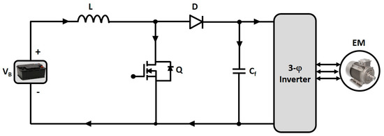
1.1. Conventional Boost DC–DC Converter (BC)
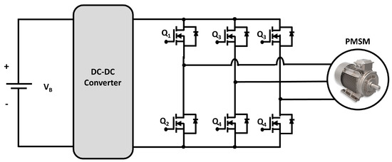
A conventional step-up or pulse-width modulation (PWM) boost converter is depicted in
Figure 22, which consists of a DC input voltage source Vs., energy storage element (i.e., inductor and capacitor), controlled switch (MOSFET, IGBT, etc.) Q, diode D, filter capacitor C, and load (electric motor). In a boost DC–DC converter, the output voltage is always more significant than the input voltage, hence the name “Boost”
[3][4][5][158,159,160].
Figure 22.
Conventional Boost DC–DC Converter.
The conventional boost converter has several merits, including simpler circuitry, lower cost due to fewer component counts, filtering and reducing electromagnetic interference efficiently, and high efficiency
[2][6][7][35,161,162]. Despite many merits, this converter cannot achieve high voltage gain; extra protection requires to protect the circuit from short-circuit, and the power-switching devices require a parallel arrangement for handling high power, and the system is quite large in volume and heavily weighted because the large capacitor that is used to filter out the output voltage ripples
[5][160].
To maintain a constant output voltage despite changes in input supply, designing a high-performance control system for DC–DC converters is very difficult due to the nonlinearity such as bifurcation, multiple equilibrium points, periodic behavior, and chaos of the converter
[8][9][10][11][12][163,164,165,166,167]. Controllers can be of two types: voltage mode controllers, and current mode controllers. Current mode controllers are widely utilized for DC–DC converters due to their several benefits
[13][14][15][16][168,169,170,171].
In
[4][159], several state-of-the-art control system design methods, such as sliding mode control (SMC)
[17][18][172,173], model predictive control (MPC)
[19][20][21][174,175,176], intelligent fuzzy logic/control system
[22][23][24][177,178,179], fractional-order proportional-integral-derivative (FOPID) control systems
[25][26][27][180,181,182] were proposed for conventional DC–DC boost converter topologies to mitigate these problems. The SMC method has invariance to internal parameter variations, insensitiveness to external disturbances, fast transient response, and can improve the robustness quickly against nonlinear uncertainties; the MPC can easily consider the state variables/input constraints in the design procedure and control the conventional DC–DC converter. The fuzzy logic-type PID control methods are generally utilized due to their effective, simple, practical, and easily tuned capabilities
[8][24][163,179]. In
[8][163], a fractional-order PID (FOPID) control method was proposed and verified via experimental studies, which showed that the control system can provide a faster recovery time and less overshoot for a DC–DC boost converter.
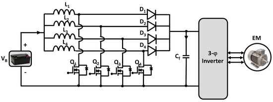
1.2. Interleaved Four-Phase Boost DC–DC Converter (IBC)
The interleaved boost converter comprises a parallel connection of boost or step-up converters, as depicted in
Figure 23. The current is divided due to a parallel connection. So, current stresses are decreased as the power losses are minimized
[28][183]. The interleaved four-phase boost DC–DC converter (IBC) comprises four similar inductors (L1, L2, L3, L4) in four step-up levels to reduce the conductor weight and input current ripples, four parallel power-switching devices for successive phase shifting, diodes, and a filtering capacitor to eliminate the output voltage ripples. All these inductors contain individual magnetic cores for better energy storing and release. As a result, the IBC topology can increase the voltage level by more than four times
[6][161].
Figure 23.
Four-phase Interleaved DC–DC Boost converter.
Moreover, the four-phase interleaved boost DC–DC converter has been chosen for EVs for its several compatible reasons, such as a reduction in inductor size and output capacitor size, a more significant reduction in input current and output voltage ripples, and higher overall system efficiency
[1][28][29][6,13,183]. Nevertheless, the IBC is sensitive to any changes in the duty cycle, high cost, and impact on the magnetic core due to any changes in load
[30][184].
The interleaved multi-phase boost converter has an enormous controlling process, but to make the system stable for significant disturbances
[22][31][32][33][34][35][36][37][38][39][177,185,186,187,188,189,190,191,192,193], some advanced control methods such as model predictive control
[32][33][186,187], fuzzy controller
[22][177], sliding mode control (SMC) and PI hybrid controller
[34][35][36][188,189,190], high order sliding mode control (HOSMC)
[31][185], active disturbance rejection control (ADRC)
[31][37][38][39][185,191,192,193] were proposed, designed, analyzed and applied to the multi-phase IBC. Moreover, an advanced hybrid Super-Twisting (ST) ADRC dual-loop controller was proposed and developed in
[31][185], where they discussed that the ST-ADRC controller provides stronger robustness against the input voltage and load disturbances, better voltage tracking performance, and a more significant reduction in both the recovery time and voltage fluctuations compared to the conventional control systems and can improve the control performance of the converter tremendously.
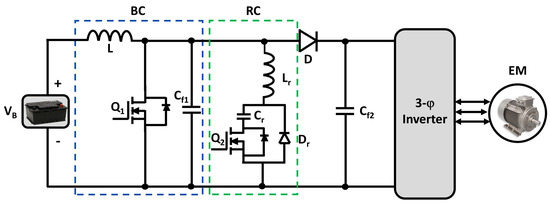
1.3. Boost DC–DC Converter with Resonant Circuit (BCRC)
Conventional boost DC–DC converters are typically operated with hard switching, which increases the switching loss of converters in BEV and PHEV powertrains. The boost DC–DC converter topologies uses a soft-switching configuration to suppress this loss. In the soft switching technique, during the switching transition (i.e., turn ON or turn OFF), voltage or current across the switch becomes zero. As a result, the product of the voltage and current is zero; hence power losses are zero. Thus, the converter can achieve high switching frequency by reducing switching losses. Due to the switching loss reduction, the heatsink size becomes lessened, which decreases the converter volume
[30][184]. The soft-switching configuration for the boost DC–DC converter with the resonant circuit is shown in
Figure 24, which consists of two switching devices, the main switch Q1 and the auxiliary switch Q2
[1][6].
Figure 24.
DC–DC Boost Converter with auxiliary Resonant Circuit.
Moreover, any abnormality in load power will not affect the converter as the converter has high safety regulations. However, BCRC is incompatible with high-power EV powertrains and does not support bidirectionality
[5][40][160,194].
Soft-switching techniques are considered the best-suited way to enhance the efficiency and reliability by reducing switching losses of electric vehicles’ DC–DC converters
[41][195]. Nevertheless, due to the necessity to exact control of numerous switches and load-dependent timing, the design of a control system for soft-switching DC–DC converters is considered complex. To meet transient requirements of voltage matching, power transfer, and response time, against system uncertainties, a robust control method is required for the electric vehicle’s soft-switching DC–DC converter because the converter must work under nonlinear transient load variations in the electric vehicle
[42][196]. In
[43][197], a proportional-integral (PI) controller for a soft-switching boost DC–DC converter with an auxiliary resonant circuit was analyzed and utilized, where they verified through simulation and experiment that the controller could improve the efficiency of the system. For electric vehicle soft-switching bidirectional DC–DC converter, a comparison with different time domains between PI and fuzzy logic controllers has been analyzed in
[44][198], where they presented during settling and peak overshoot rise, fuzzy controller has better performance than PI controller.
Although there are several established analog controllers available in the market to control soft-switching resonant circuit DC–DC boost converters, due to the low price-to-performance ratio, high-frequency conversion system, and latest developments of microcontrollers/digital signal processors (DSP), digital controllers have been growing interest in the field of low-medium power DC–DC converter topologies
[45][199]. However, the design of digital controllers for auxiliary resonant circuit boost converters was discussed in very few papers. In
[45][199], some investigations were made for the digital controller design of these kinds of DC–DC converter topologies to bridge this gap. In
[46][200], a digital control with a pole-zero placement technique was proposed, designed, and verified for a soft-switching high gain DC–DC boost converter through simulation and experimental studies. They showed that against various disturbances, the designed controller could regulate the load voltage. In
[47][201], a robust digital PID controller for a soft-switching H-bridge boost converter is proposed and designed where they ensure step loads and source rejection with robust performance against converter parameter uncertainties, system stability, and load voltage regulation. In
[45][199], several single-loop control methods were discussed; among them, the single-loop voltage-mode control technique is widely utilized due to its good dynamic response and simple controlling strategy. They designed the proposed digital voltage-mode controller and experimentally verified the reliability of the designed control scheme. In
[42][196], a fixed boundary layer sliding mode control (FBLSMC) method for an electric vehicle soft-switching DC–DC converter was presented and discussed so that the FBLSMC can fix the boundary width and the instability of traditional sliding mode control can be avoided.
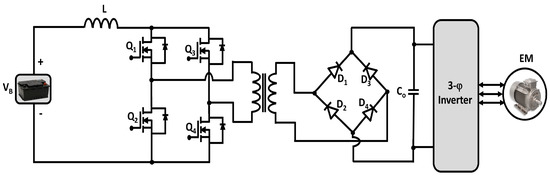
1.4. Full Bridge Boost DC–DC Converter (FBC)
The circuit diagram of an isolated full-bridge bidirectional DC–DC converter is depicted in
Figure 25. This converter works in buck-and-boost mode, thus it is a bidirectional converter. In the forward direction, it works as a buck converter; in the backward direction, it operates as a boost converter
[48][202]. Due to this bidirectionality, an isolated full-bridge bidirectional DC–DC converter can charge the batteries and provide the voltage to the load. The bidirectional full-bridge DC–DC converter has three working stages: DC–AC conversion as an inverter; step-up/step-down AC voltage with a high-frequency transformer (HFT); and AC–DC conversion as a rectifier
[1][6].
Figure 25.
Isolated Full-bridge Boost DC–DC Converter.
Furthermore, the interior high-frequency transformer (HFT) provides galvanic isolation between the input and the output side and offers high step-up voltage. The converter can provide around 92% of efficiency at a 30 kW load
[6][161]. However, the leakage inductance of the HFT has a crucial effect on the switching circuit due to high electrical stresses across the switching devices. Thus, the switching course required a clamping circuit to resolve the peak voltage issue
[30][49][50][184,203,204].
As discussed earlier, digital controllers are outrunning analog controllers in the application of DC–DC converters due to several advantages, such as simplifying complicated functions and accomplishing wide-load range soft-switching. Therefore, in
[51][205], a simple digital controller for an isolated full-bridge DC–DC converter of electric vehicle applications was presented where the driving signals for all power switching devices and the feedback control of the output power system were controlled via a single peripheral interface controller (PIC) microcomputer. For maintaining the output voltage, a digital PI control technique with a field-programmable gate array (FPGA) was presented and designed in
[52][206]. In
[32][186], two predictive model control (MPC), such as linear MPC (LMPC), and non-linear MPC (NMPC) techniques for an isolated DC–DC FBC, were presented and designed through both simulation and experimental results, where it was revealed that the peak current protection and the voltage regulation could be successfully achieved with both of these MPC algorithms. However, they do not assure better performance in a longer prediction horizon, and the linear MPC has a longer computational time than the non-linear MPC. In
[53][207], a comparative performance analysis among linear peak current mode control (LPCM), non-linear carrier control (NLC), and predictive switching modulator (PSM) control schemes for isolated DC–DC FBC were presented. They proposed the PSM control scheme for IFBC due to its several advantages, such as steady-state stability performance and good transient over both LPCM and NLC schemes. Moreover, the predictive switching modulator control scheme can also reduce the rise and settling time and the peak overshoot during load changes. In addition, the PSM control scheme can reduce the size of electromagnetic interference (EMI) by extending the range of continuous conduction mode, and to generate the carrier waveform proposed controller requires only two reset integrators, whereas the NLC requires three rest integrators.
However, digital control techniques are needed to fulfill a certain condition for the resolution of the analog-to-digital converter (ADC) and resolution of PWM, otherwise, the output voltage oscillates, which is not the desired phenomenon of a controller. Furthermore, digital controllers are inherently slower than conventional analog PI controllers due to the requirements of heavy calculations. Hence, to control the isolated full-bridge DC–DC boost converter, traditional analog PI control techniques are still preferred
[52][206].
1.5. Isolated ZVS DC–DC Converter (ZVSC)
For isolation, cold starting, and soft switching, an isolated ZVS DC–DC converter is needed
[54][55][208,209].
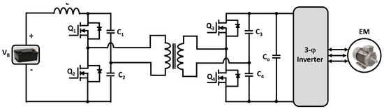
Figure 26 depicts an isolated zero-voltage switching DC–DC converter (ZVSC), where a dual half-bridge topology is placed on both sides of the transformer, and for soft-switching, each power switching device has a parallel capacitor
[54][208]. ZVSC has a simple control technique, higher efficiency, soft-switching without extra circuity, high-power density, less component count, compact packaging, and lightweight, and no real device rating consequences compared to the traditional full-bridge DC–DC converter
[6][54][161,208].
Figure 26.
Isolated Zero Voltage Switching (ZVS) DC–DC Converter.
Nevertheless, ZVS converters are unsuitable for high-power (>10 kW) EV applications due to the absence of tolerance operation and high voltage stress remaining across the power-switching devices. The full load current must be managed across the switches (Q
1–Q
4) by dividing DC capacitors (C
1–C
4). Furthermore, for filtering the output voltage ripples, a larger capacitor is needed
[54][56][57][58][59][208,210,211,212,213].
There are two conventional control schemes for controlling the isolated half-bridge ZVS DC–DC boost converter: symmetric and asymmetric. To control the isolated ZVSC, the conventional symmetric PWM control scheme is not a suitable candidate due to the soft-switching counterpart. For controlling the isolated ZVS boost converter, the asymmetric control scheme was proposed in
[60][61][62][214,215,216]. In
[60][214], a conventional asymmetric phase-shift control method was utilized to control the isolated half-bridge ZVSC by charging the upper and lower secondary capacitors differently. They adjusted the switching time of the secondary switches with this different charging mechanism. As a result, the voltage imbalance occurred.
Although an isolated half-bridge ZVS DC–DC converter can be controlled via a conventional asymmetric control scheme, due to the variable voltage and current equipment stresses, the asymmetric control scheme is unsuitable for wide-range input voltage
[63][217]. As a solution in
[63][64][217,218], a new asymmetric duty-cycle shifted PWM (DCS PWM) control method was proposed for an isolated half-bridge ZVS DC–DC boost converter to achieve zero voltage-switching and soft-switching behavior for all switching devices at a wide-range input voltage without adding additional components and without causing the asymmetric penalties. They experimentally verified that the proposed controller could eliminate the ringing and switching losses and operate at a higher efficiency and frequency than the conventional symmetric and asymmetric control schemes. In the DCS PWM control scheme, the lagging switch was achieved by shortening the interval between two symmetric PWM driving signals. Hence, one of the two symmetric PWM driving signals was shifted close to the other
[63][217]. Moreover, in
[65][219], a dual closed-loop controller of the inner balanced current loop and the outer voltage loop was designed to control and achieve the stability and robustness of a current-fed half-bridge isolated ZVS DC–DC converter of a hybrid electric vehicle. They verified the effectiveness of the designed controller with PSIM and MATLAB/Simulink simulations at various input voltages.
1.6. Isolated Multiport DC–DC Converter (MPC)
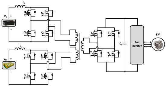
The isolated multiport DC–DC converter is used when more than one input source is needed with galvanic isolation between the source and load. The multiport converter is classified into three main categories: single-input multi-output (SIMO) converter, multi-input-single-output (MISO) converter, and the multi-input-multi-output (MIMO) converter. Among them, the MIMO multiport DC–DC converter is used in battery and plug-in hybrid vehicles. It has coupled multiple input sources (generally supercapacitor and battery) and uses them as a single source with the advantages of various sources. The circuit diagram of the MIMO-MPC boost DC–DC converter is shown in
Figure 27, which consists of a parallel connection of two boost DC–DC converters with bidirectional power flow, and it is advantageous for BEVs powertrains because it allows the converter to recharge the input sources during regenerative braking. Because of this, the effectiveness and functionality of the MPC increase, which makes it a high-power density converter. Moreover, all the input ports, as well as the output port, remain isolated from each other due to the interior multi-winding transformer
[1][2][29][6,13,35].
Figure 27.
Isolated Multiport DC–DC Converter.
Nevertheless, MPC has a great component count, which makes synchronization difficult. Also, the weight of the converter increases due to the presence of the multi-winding transformer; it is sensitive to any changes in the duty cycle and analyzing the converter’s steady-state and transient conditions is complex
[66][67][68][69][220,221,222,223].
A control scheme is needed to combine multiple input sources, such as batteries and supercapacitors, via MPC, and is supplied to a single output. Several control schemes, such as a novel PWM plus-phase angle shift (PPAS) control scheme
[70][224], PIC control-based scheme
[71][225], PID control scheme
[71][225], hybrid phase-shift and duty cycle-based control scheme
[72][226] have been proposed and designed by many researchers to control multi-port DC–DC converters. The PAPS control scheme can achieve decoupled control and improve the device-sharing ratio among different ports
[70][224]. Moreover, the hybrid phase-shift and duty cycle-based control scheme ensure the balance of each port power by the phase-shift control based on a reference value and the desired load voltage level kept by the duty cycle control. Therefore, this new control scheme can easily achieve the wide range of power flow control and voltage regulation
[72][226].
1.7. Multidevice Interleaved DC–DC Bidirectional Converter (MDIBC)
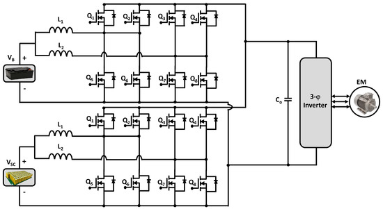
A transformer is a heavy component that increases the weight of an isolated boost DC–DC converter. For this reason, a non-isolated multidevice interleaved bidirectional DC–DC converter is used in high-power vehicular applications. A non-isolated multi-device interleaved bidirectional DC–DC converter (MDIBC) is shown in
Figure 28, which uses a battery as the primary power source and a supercapacitor as a secondary or auxiliary power source. MDIBC is a multiphase multiport bidirectional converter consisting of a phase interleaving technique with four high-frequency switching devices per phase. The number of parallel devices per phase decreases with the increasing number of phases
[66][220]. Multidevice interleaved boost DC–DC converters merge the power from two or more input sources and are supplied at a constant single output voltage level.
Figure 28.
Bidirectional Multidevice Interleaved DC–DC Boost Converter.
Furthermore, MDIBC can sustain the required input current and output voltage ripples level without increasing the value of passive components (inductors and capacitors). The electrical breakdown chances are most negligible in MDIBC because a common control technique, a common heat-sink, and a standard capacitor are mutually shared by both ports, which enhances the reliability of the multidevice interleaved boost converter compared to conventional converter topologies. The overall system efficiency and effectiveness of MDIBC increases due to the regenerative braking power using the bidirectional power flow capability. Moreover, dividing the current between multiple phases is the central prominence of the multidevice interleaved boost converter. The input current ripples reduce due to the operation of the gate signals with the interleaving technique
[1][6].
On the contrary, MDIBC has a high component count, stability, and sensitivity problem because of changes in the current load profile. Analyzing the characteristics at the transient and steady-state conditions is difficult
[73][74][75][76][77][78][227,228,229,230,231,232]. Although current ripples, volume, cost-effectiveness, and the weight of vehicular power electronics interfaces are the main design challenges, bulky weight elements (filtering capacitor, inductor, and heat-sink) of MDIBC are reduced by the interleaving technique as well as by achieving high switching frequency, which fulfills the design goals
[1][6].
For a common high-voltage DC-bus to control power regulation, the design of the controller plays an important role
[74][228]. For controlling the multidevice interleaved DC–DC boost converter for electric vehicle applications, there are several control schemes, such as direct digital control (DDC) based digital dual-loop control
[74][228], dynamic evolution control
[79][233], digital phase shift control
[80][234], advanced sliding mode control (ASMC)
[81][235], voltage and current controllers
[82][236], and fuzzy logic controllers (FLCs)
[83][84][237,238].
To eliminate the chattering effects, which is one of the main drawbacks of the conventional sliding mode control, the ASMC controller was designed and analyzed. The elimination of chattering effects and the reduction of the voltage and current ripples with a faster transient response, stable steady-state response, and slight overshoot during startup can easily be achieved with this advanced SMC scheme
[81][235]. Furthermore, the digital dual-loop control based on direct digital control was designed and validated via simulation and experimental results to achieve the proper regulator for the converter with a fast transient response, high performance, and high efficiency
[74][228].
Although conventional controllers are easy and straightforward to design, due to several disadvantages, such as working point dependent performance, the stabilization problem, and control parameters need to be changed whenever the input supply and/or output parameters change, etc. Among the conventional controllers, FLCs are widely utilized in the field of power electronics MDIBC converters applications
[85][239]. Moreover, the FLCs are simple to design and implement and are practical and powerful under parameter variations for both linear and non-linear systems
[86][87][88][240,241,242]. Hence, FLCs provide better performance for traction applications than conventional controllers
[84][238].
2. Energy Storage
The battery is modeled as a fixed voltage source with an internal resistance
[89][90][243,244]. High performance is required for batteries since they are the core component of an EV
[91][245]. Several types of rechargeable batteries, such as Ni–Cd, Ni–MH, Lead–acid, and Lithium–ion (Li–ion), are now available in the world markets for powering electric vehicles
[92][93][94][40,246,247]. Among all battery types, Li–ion batteries are considered the best and are widely used in EVs due to their superior characteristics and performance, such as high energy and power density, long service life, negligible memory effect, low self-discharge rate, and environmental friendliness
[94][95][96][247,248,249]. Due to these advantages mentioned above, EVs commonly utilize Li–ion batteries as the primary energy source
[97][98][99][250,251,252]. Nevertheless, the biggest problems of these electrified transportations, i.e., BEVs, trucks, and buses, are the longer charging times and low driving range, averting their fast growth
[100][17]. Hence, a higher voltage (800 V) Li–ion battery (i.e., lithium titanate, lithium nickel manganese cobalt oxide, and lithium iron phosphate oxide) is needed together with fast chargers (FCs) or extreme fast chargers (XFCs)
[1][101][5,6].
In order to describe the electrical behavior of a battery, several test models exist
[90][244]. In terms of the time required for 845 km inter-city travel, a comparison between EVs and internal combustion engine vehicles (ICEVs) was made in
[102][4], where it was disclosed that, based on the present battery capabilities, charges with a power greater than 400 kW are required to have comparable travel time between EVs and ICEVs.
Furthermore, the advantage of XFC in EVs is that it enables a higher-voltage DC link. Higher DC-link voltage provides several benefits, such as lower manufacturing cost, higher power density, faster charging, lighter cables, lower weight, and loss for EV applications
[103][1]. Hence, the motor current can be reduced due to the high-voltage operation which achieves high efficiency and low conduction losses
[104][105][253,254]. Because of these advantages, manufacturing companies are moving toward a higher-voltage DC link.
However, despite all the merits of the high-voltage DC-link, some demerits, such as higher switching losses due to higher voltage, cannot be neglected. As a result, the overall efficiency can be decreased if the inverter topology for converting DC–AC remains the same
[97][250]. Hence, the conventional two-level inverter is not recommended for a high-voltage DC link. Therefore, in electric vehicles, a multi-level inverter (MLI) can be a well-suited solution for high-voltage batteries
[1], [103]which will be discussed in Section 5.
3. Inverter
3.1. Two-Level Inverter (TLI)
The two-level inverter is depicted in
Figure 29, which consists of six power-switching devices. These six power switches are connected into three legs, and each leg contains two switches, which are connected in series. An antiparallel diode is connected to each switch to allow the current to flow in the opposite direction. By controlling these six switches in different manners, the inverter can generate eight other states
[89][90][243,244].
Figure 29.
Topology of a two-level inverter (TLI).
The requirement of large filters to mitigate the output harmonics and the limited capabilities for high-power applications are the major demerits of conventional two-level inverters (TLI)
[106][255]. Hence, to reduce the harmonics and filtering efforts, multilevel inverter (MLI) topologies were introduced
[107][108][36,256].
In recent decades, power converters have become very popular for a wide range of applications, such as traction, energy conversion, and motor driver applications
[109][257]. A new topology of a two-level voltage source inverter (VSI) was introduced in
[110][258] that utilized a reduced number of expensive yet high-performance transistor counts, with three transistors only, having a similar performance as compared to the conventional six-transistor VSIs. Although the three-transistor VSI is designed for motor control applications, it has never been adopted for electric vehicle applications. Thus, this topology could be investigated for electric vehicle applications. Due to the high-power variable voltage and frequency supply requirement, the AC drivers are more ascendant than DC drivers
[111][259]. Therefore, the requirement of control schemes for these power converters is also ascendant; hence, researchers present, propose, and design new schemes every year
[112][113][260,261]. There are several control schemes, such as triangle comparison-based PWM (TCPWM)
[110][258], sine-wave pulse width modulation (SPWM)
[111][114][259,262], space vector-based PWM (SVPWM)
[111][115][259,263], novel predictive variable structure-switching-based current controller
[109][257], and modulated model predictive control (MMPC)
[116][264] are available in the market of electric vehicles to control three-phase motor drive two-level power inverters. Among them, SPWM was widely utilized for its merits, such as its simple circuit, rugged and easy controllability, low power dissipation, compatibility of a digital microprocessor, and lower switching losses
[114][262]. In
[111][115][259,263], a comparison between SPWM and SVPWM control schemes for two-level inverters was conducted, showing that the SVPWM has the highest possible peak phase fundamental, less output waveform distortion, more efficient dc-bus voltage compared to the SPWM control scheme. Therefore, space vector PWM is the best-suited control scheme to drive AC induction, brushless DC, switched reluctance, and permanent magnet synchronous motors via three-phase two-level inverters
[111][259].
3.2. Multi-Level Inverter (MLI)
To gain less current and voltage total harmonic distortion (THD), less voltage stress on semiconductor devices, high efficiency, low EMI, and common-mode voltage, many conventional two-level inverters have been replaced in the past decades by their multilevel counterparts. In addition, due to the modularity and fault tolerance capability, some MLI topologies becomes more beneficial for specific applications
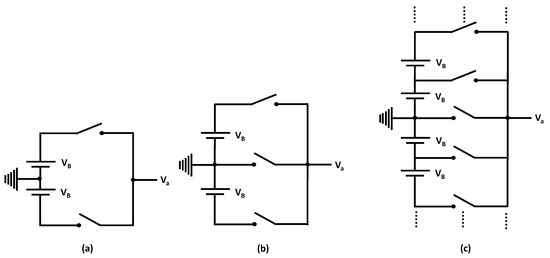
[117][118][265,266]. The basic concept of an MLI is depicted in
Figure 130, where switching devices carry much lower voltages than TLI, and the output filter size is decreased due to the ability to produce various voltage levels with better voltage/current quality at the lower switching frequency. As a result, higher power levels can be achieved with MLIs without switches derating
[119][37].
Figure 130.
One leg of (
a
) 2-level, (
b
) 3-level and (
c
)
Although multiple-DC-source multilevel inverters (MDCS-MLIs) require multiple isolated DC supplies
[120][121][267,268], in high-power motor driving applications like electric vehicles, cascaded H-bridge inverter (CHB) MDCS-MLIs are most commonly utilized due to their high modularity and identical voltage rating of the employed switches
[119][37]. For military combat vehicles and heavy-duty trucks, cascaded H-bridge (CHB) MLI was first recommended in 1998 as a suitable choice due to it can drive high-voltage motors easily with low-voltage switching devices
[122][269]. Furthermore, there are many different topologies, such as Neutral Point Clamped (NPC) topology
[123][270], Packed U-Cells (PUC) topology
[124][271], and Flying Capacitor Inverter (FCI) topology
[125][272], by which a multi-level inverter can be built but the topology discussed
in th
ereis paper is the cascaded multilevel inverter
[90][244]. Moreover, a novel H-bridge two-transistor cascaded multi-level voltage source converter is introduced in
[126][273], and this promising multi-level converter could be explored for electrified transportation applications.
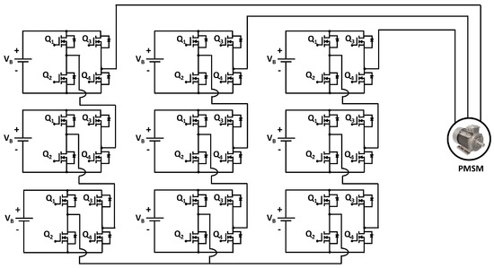
Figure 131 depicts a multi-level inverter, which consists of series-connected H-bridges. These H-bridges can be controlled independently, and each H-bridges consists of an individual energy storage V
DCML and four power-switching devices. The MLI can create different outputs like V
DCML, −V
DCML, 0, and open circuits by controlling these power switches in different manners
[89][243].
Figure 311. Topology of a 7-level multilevel inverter (MLI) [89][90]. Topology of a 7-level multilevel inverter (MLI) [243,244].
Therefore, because of their remarkable characteristics, such as high-power and low electromagnetic interference (EMI), MLIs are utilized in many medium and high-power applications. However, the challenges like the suppression of circulating currents, reduction of reliability due to the higher component count (i.e., semiconductor devices and capacitors), and capacitor voltage balancing are needed to be addressed to utilize the MLI
[127][128][129][274,275,276].
To control cascaded H-bridge multi-level inverter, several types of feed-forward and feed-back PWM control schemes such as sinusoidal PWM (SPWM)
[130][277], space vector PWM (SVPWM)
[130][277], third harmonic injection PWM (THI-PWM)
[131][278], etc. have been presented and designed. A novel multicarrier SPWM control scheme for cascaded H-bridge seven-level inverter was proposed in
[130][277], where the main objectives are to enhance the fundamental component of the output voltage and increase the per-phase carrier utilization by more than one. In
[130][277], a simple SVPWM control scheme has been proposed for MLI topology where the controller utilizes a simple mapping and can be easily implemented using a microcontroller. On the other hand, the THI-PWM control scheme modifies the modulation signal and the carrier signal by adding third harmonic and phase-shifting processes to control the power converter topologies
[132][279]. Furthermore, a performance analysis among SPWM, SVPWM, and THI-PWM in
[133][280] where it was found that performance wise SVPWM and THI-PWM very similar, but when converter topology was considered, multi-level converters performed more efficiently with THI-PWM as compared with SPWM or SVPWM. Moreover, the DC link voltage utilization was also more than that of SVPWM.
Although the SVPWM for an MLI is complicated to implement, it is the most widely utilized control scheme for a multilevel inverter due to its several tremendous advantages such as the highest possible peak phase fundamental, more efficient dc-bus voltage, less output waveform distortion compared to SPWM, and THI-PWM
[131][278].
4. Motor and Drive
4.1. Traction Motor
For traction applications (i.e., electric vehicles, trains, ships, aircraft), designing electric motors have hard and fast operational requirements because of high efficiency, high power density, high specific torque, low noise, fast dynamic response, high torque at low speeds, low torque at high speeds, low cost, overload capability, fault tolerance, high mechanical robustness, and ruggedness is required for traction motors
[134][135][38,281]. The design should be such that the machine can produce high starting torque and low torque with high power at high speed. Therefore, to design an electric traction motor, modeling and analysis are required from multiple engineering domains to satisfy all these requirements
[104][136][253,282].
In terms of suitability for EV applications, various types of electric motors (EMs) have been presented and analyzed in
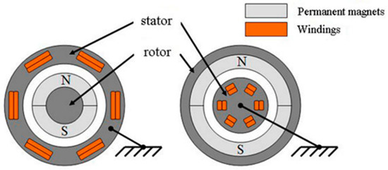
[104][137][138][139][140][141][142][143][144][145][253,283,284,285,286,287,288,289,290,291]. Among them, permanent magnet synchronous motors are widely used due to their high efficiency and power density
[146][147][148][292,293,294], depicted in
Figure 132. There are several types of permanent magnet (PM) machines that can be utilized as traction motors they are surface-mounted permanent magnet synchronous machines (SM-PMSM)
[149][295], brushless direct current machines (BLDCM)
[150][151][296,297], interior permanent magnet synchronous machines (IPMSM)
[152][153][154][298,299,300] for both axial and radial flux magnetic configurations
[151][297]. However, PMSM traction motors are highly temperature sensitive. So, thermal management is a crucial aspect to design for these motors since they are expected to be performed under extreme temperature conditions as traction motors. To design and develop an accurate traction model, many parameters play an important role, such as heat transfer coefficients, boundary conditions, material properties, and geometry restrictions
[155][301].
Figure 132.
Structure of Permanent Magnet Synchronous Machine (PMSM).
Although several advantages make the PM motors a suitable nominee for EVs, the resources of the permanent magnet are limited, and the increasing demand for electric vehicles are increasing the price of the PM continuously. Moreover, the cost of the rare earth metal neodymium magnet (NdFeB) was 250 US$/Kg in 2005. On the other hand, in 2012 it was increased to 437 USD/Kg, which eventually affected the price-sensitive markets such as EVs, electric bikes, etc.
[156][302]. Demagnetization analysis is an integral part of the design process to define the performance of a permanent magnet traction motor at a particular operating temperature
[157][303]. Hence, the design parameters and motor geometry must be synthesized to prevent the reduction in output torque due to the irreversible demagnetization of permanent magnets
[153][299]. From a mechanical point of view, the components of an electric motor drive system, such as bearings, couplings, and shafts, need to be analyzed to ensure reliable operation
[155][301].
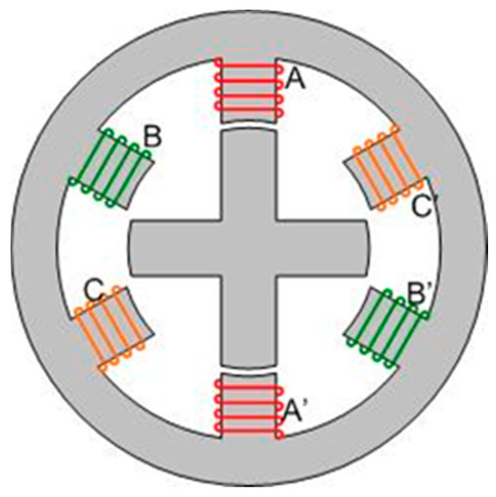
As a result, PM-free machines such as switched reluctance machines (SRMs), induction machines (IMs), and synchronous reluctance machines (SyncRels) have come into interest. Switched reluctance machine (SRM) is considered a strong candidate for electric bikes and scooters due to their robust structure and low cost
[158][14], depicted in
Figure 1 33.
Figure 133.
Structure of Switched Reluctance Machine (SRM).
Moreover, they can be utilized as secondary electrical power generation in electric aircraft engines due to their harsh environment operating ability
[159][304]. In
[152][298], several types of switched reluctance machines (SRMs) topologies such as segmental rotor SRM (SR-SRM), double stator SRM (DSSRM), and mutually coupled SRM (MCSRMs) are presented and analyzed with their performance comparison in terms of their torque density, torque ripple, power factor, and voltage utilization. In addition, the opportunities, challenges, advantages, and disadvantages of SRM drives are also discussed. In the growing electric propulsion market, because of the unpredictable cost of rare earth metals and supply chain issues of conventional interior permanent magnet synchronous machines, the switched reluctance motor (SRM) drives have started to take their rightful place as a reliable alternative
[152][298]. Furthermore, a new PM-less brushless synchronous machine that uses sub-harmonic magnetomotive force (MMF) to excite the rotor winding was introduced in
[160][161][305,306], where the stators use novel two layers of winding in
[160][305] and three layers in
[161][306] for the brushless operation of the synchronous machine.
However, although SRMs have been proposed in many research articles instead of conventional IPMSMSs due to their comparable power density/torque, there is no SRM-based powertrain for electric vehicles in the market so far
[148][152][162][294,298,307]. Nevertheless, the overall system installation and manufacturing cost can be reduced by 30–40%, and the power density can be improved with 10–20% lesser volume by utilizing the integrated motor drive (IMD)
[163][164][308,309].
4.2. Integrated Motor Drive
The structural integration of an electric motor drive, such as the elimination of shielded connection cables, centralized controller cabinet, and high current/voltage bus bars, is referred to as the integrated motor drive (IMD). Due to the rapidly growing interest in electric vehicles, the role of the electrified actuation system is becoming more critical. An electric vehicle requires highly efficient and reliable steering, suspension, braking, and heavy-duty actuators
[165][166][167][168][310,311,312,313]. The integrated motor drive offers viable solutions for the increased demands of high-power density and highly efficient electro-hydrostatic actuator (EHA) systems
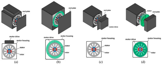
[169][314]. In
[169][314], four different IMD configurations were reported: (i) radially housing-mounted (RHM); (ii) axially housing-mounted (AHM); (iii) radially stator iron-mounted (RSM)l and (iv) axially stator iron-mounted (ASM), which are depicted in
Figure 134a–d, respectively
[169][170][314,315].
Figure 134.
Conceptual illustration of four different IMD configurations: (
a
) RHM; (
b
) RSM; (
c
) AHM; and (
Moreover, the performance of the IMDs in high-temperature operation, fault tolerance, power density, low switching and conduction losses, lower ON-state resistance, and high efficiency can significantly be achieved by utilizing wide-bandgap semiconductor (WBGS) devices, such as gallium nitride (GaN) and silicon carbide (SiC), in motor drive technology
[163][172][173][174][175][176][32,33,308,316,317,318]. Although the cost of WBGS-based devices is much higher than silicon-based devices due to the reduction in cooling, control cabinet, passive components, packaging, and connecting wires, the overall IMD system cost can be significantly reduced by using WBGS devices
[169][314].