| Version | Summary | Created by | Modification | Content Size | Created at | Operation |
|---|---|---|---|---|---|---|
| 1 | Shantanu PARDHI | -- | 7053 | 2023-01-05 17:04:05 | | | |
| 2 | Jason Zhu | + 227 word(s) | 7280 | 2023-01-06 06:05:58 | | | | |
| 3 | Jason Zhu | Meta information modification | 7280 | 2023-02-14 09:27:54 | | |
Video Upload Options
Long-haul heavy-duty vehicles, including trucks and coaches, contribute to a substantial portion of the modern-day European carbon footprint and pose a major challenge in emissions reduction due to their energy-intensive usage. Depending on the hydrogen fuel source, the use of fuel cell electric vehicles (FCEV) for long-haul applications has shown significant potential in reducing road freight CO2 emissions until the possible maturity of future long-distance battery-electric mobility. Fuel cell heavy-duty (HD) propulsion presents some specific characteristics, advantages and operating constraints, along with the notable possibility of gains in powertrain efficiency and usability through improved system design and intelligent onboard energy and thermal management.
1. Introduction
1.1. Hydrogen and Battery Electric Propulsion for Long-Haul Decarbonisation
1.2. Fuel Cells over Combustion Engines for Hydrogen Mobility
1.3. Renewable Hydrogen towards Sustainability
1.4. Challenges in H2 Refuelling
1.5. HD Fuel Cell Vehicle Total Cost of Ownership
2. FCEV Heavy-Duty Applications
3. FCEV Powertrain
3.1. Powertrain Topology
3.1.1. eDrive and Transmission
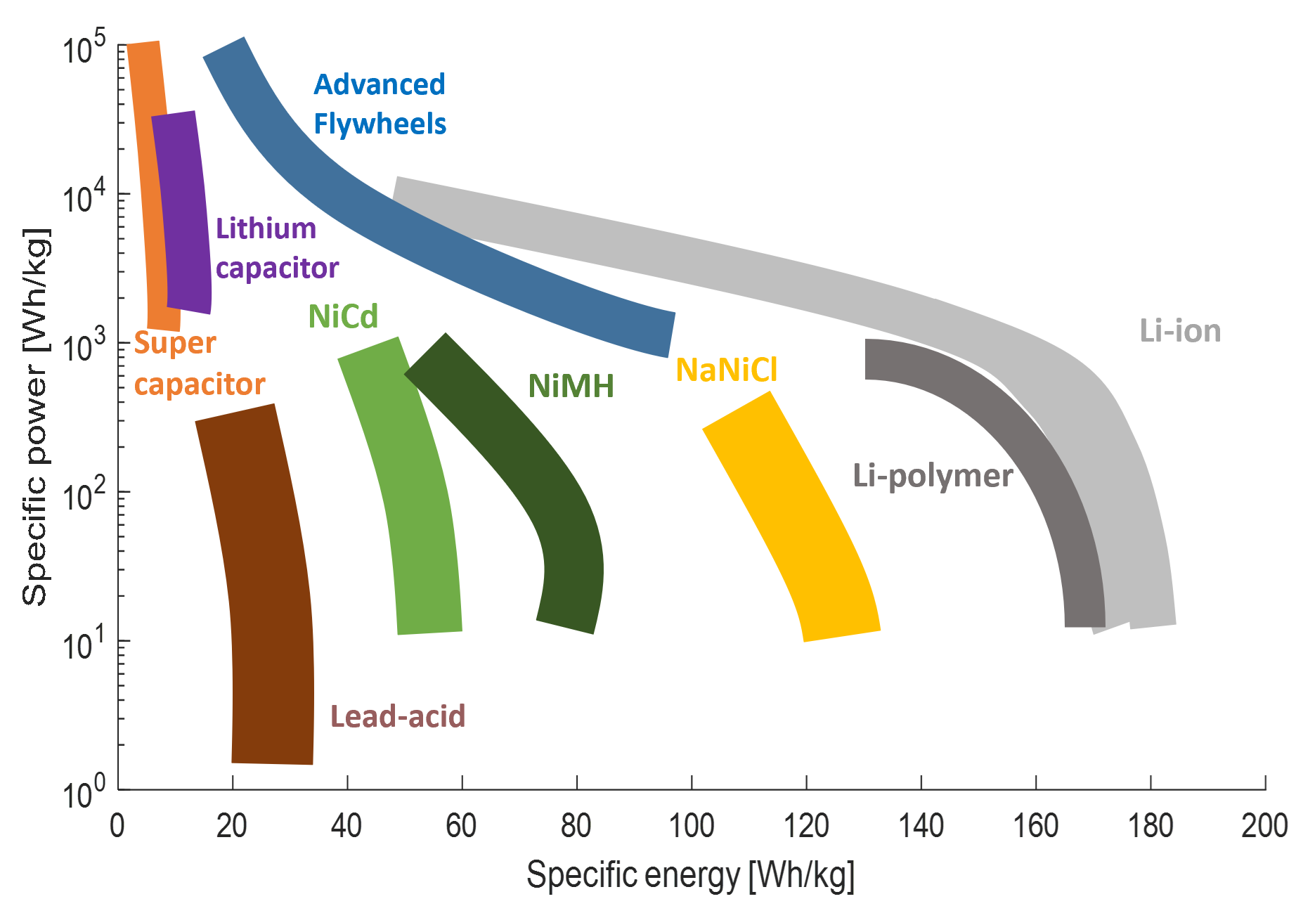
3.1.2. Power Sources
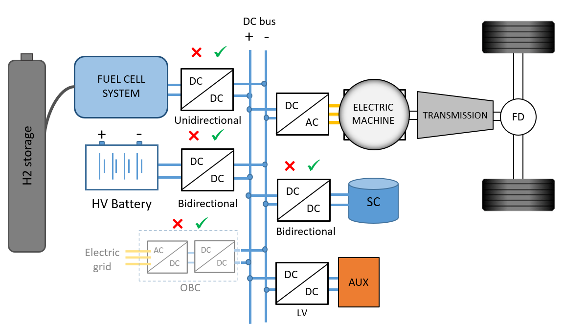
3.1.3. DC Link and Converter Combinations
3.1.4. Auxiliary Loads
3.1.5. On-Board H2 Storage
| Method | Volumetric Density [gH2/L] | Gravimetric Density [gH2/kg] | Pressure [bar] | Temperature [◦C] |
| Compressed 350 | 16 | 55 | 350 | Ambient |
| Compressed 700 | 27 | 57 | 700 | Ambient |
| Liquid | 36 | 75 | 1 to 70 | -253 to -244 |
| Cryo compressed | 72 | 55 | 300 | -150 to -240 |
| Metal hydride (NaAlH4) | 70 | 35 | 20 | 260 to 425 |
| Metal hydride (LiBH + MgH2) | 80 | 80 | - | - |
| Metal borohydride (AL(BH4)3) | 70 | 100 | 105 | -140 |
| Liquid organic hydrogen carrier | 56 | 65 | Ambient | Ambient |
| Metal organic framework | 13 | 50 | 1 to 350 | -203 to ambient |
3.2. HD 40T Fuel Cell Truck Simulation and Energy Audit
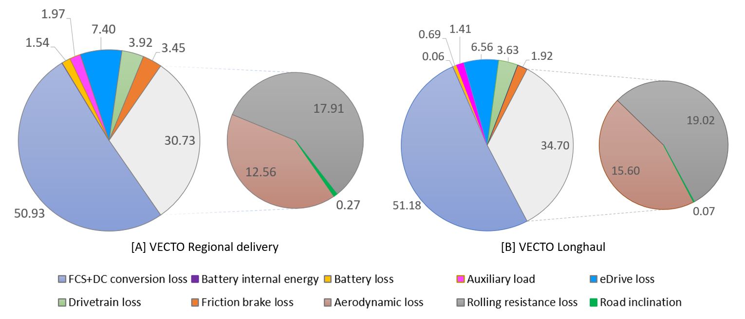
Figure 3. Percentage distribution of H2 fuel energy expenditures and losses among different powertrain subsystems and driving resistances for 40-tonne fuel cell truck running on (A) VECTO Regional Delivery and (B) Longhaul drive cycles.
3.3. Fuel Cell System—Balance of Plant
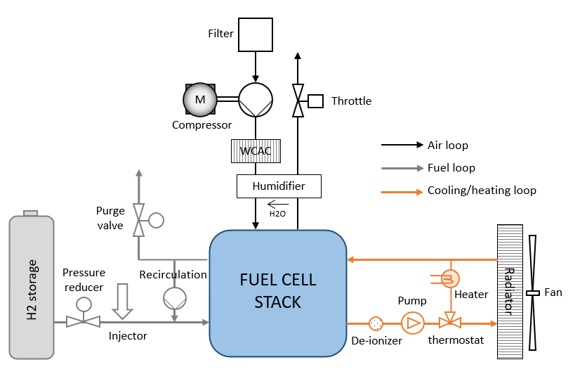
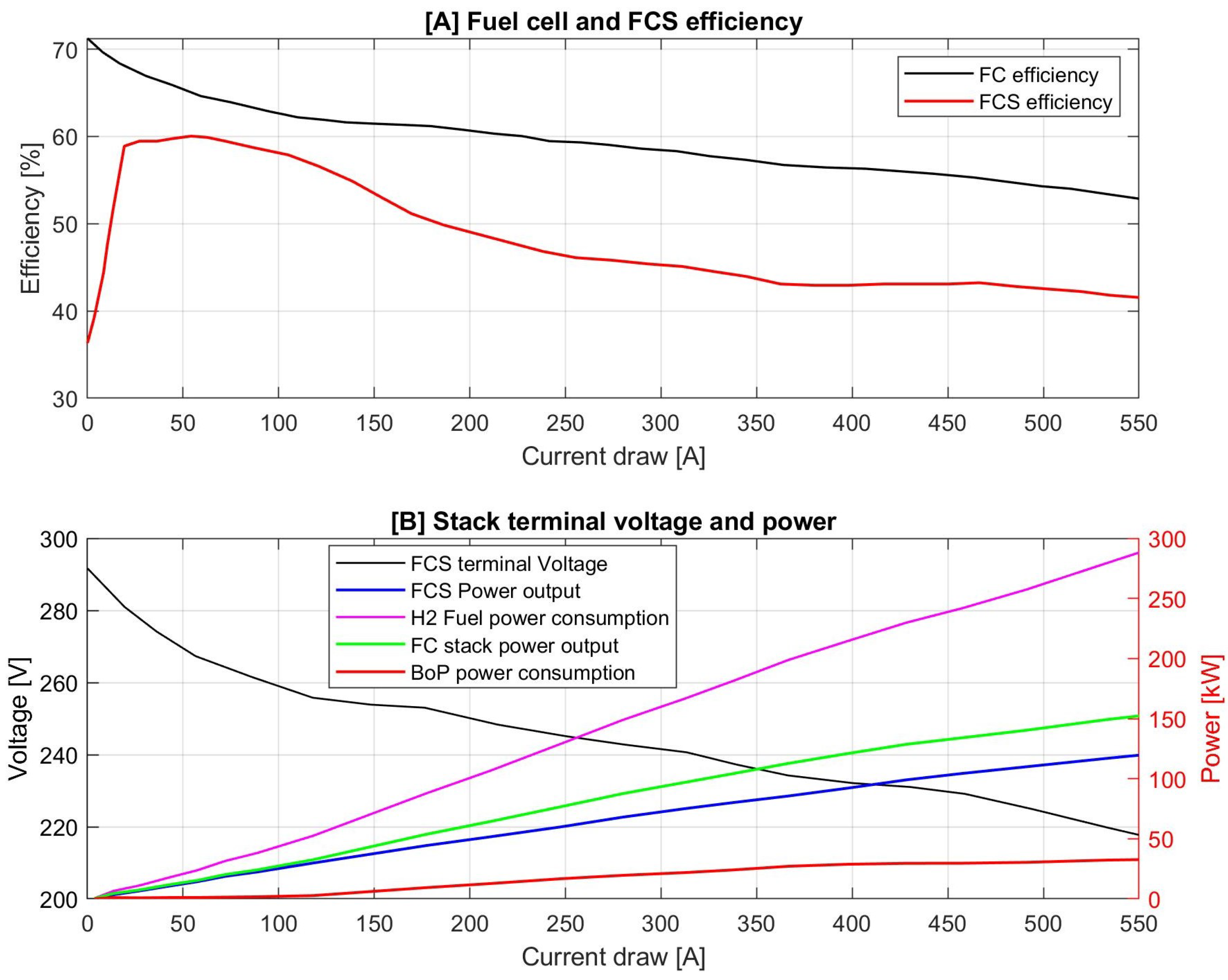
Figure 5. (A) Fuel cell stack and fuel cell system energy conversion efficiencies based on current draw inspired from Toyota Mirai 2 bench-marking tests performed by AVL and FEV, (B) corresponding stack terminal voltage drop and FCS, FC stack, BoP components, H2 fuel power [117][126].
3.3.1. Effect of Temperature, Pressure and Humidity
3.3.2. Air System
3.3.3. Fuel System
3.3.4. Thermal Management System
3.4. Proton Exchange Membrane Fuel cell

3.5. Fuel Cell Ageing
-
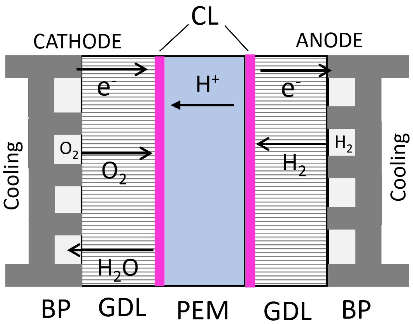
Design changes in the inlet flow field, air-fuel system and the MEA structure can lower non-uniformity of humidity, reactant concentration, temperature and pressure across FC surface under extreme operating conditions such as rapid transients, sub-zero cold starts, very low and high load. In terms of materials, membrane reinforcement by polytetrafluoroethylene binder (PTFE) has been shown to improve FC lifetime. Chemical and electrochemical performance could be extended by incorporating inhibitors, free-radical stabilisers and sacrificial materials in the membrane. Platinum dissolution can be lowered by changing the CL design and using Pt-based compounds. By changing the design of PTFE and ionomer using water-blocking components, water retention can be improved on the anode side to lower carbon corrosion issues. Increasing the PTFE content can also improve the water management ability of the GDL. Coating with noble metals, nitrides or carbide-based alloys is the current subject for bipolar plate ageing mitigation. However, the coating can lead to reduced mechanical strength and fractures under high load, especially under repeated thermal cycling, and is a subject of current research [158].
-
By using intelligent control strategies at the FCS level, flow field non-uniformity can be further lowered by preparing the FCS for immediate operating events, especially under transient driving conditions in terms of humidity, boost pressure, electrode reactant concentrations, preconditioning of BoP components, etc. Membrane reliability can be improved by maintaining high relative humidity and water content, especially at the reactant inlets. The durability of the CL can be improved by maintaining appropriate conditions such as relative humidity and low temperature throughout the operation [158].
-
The effect of transient driving, sub-zero cold starts, very high and low load operation can be further lowered by regulating the load demand from the FCS in different parts of the drive cycle using the added degree of freedom from the hybridised FCEV powertrain. This will include the usage of OTA predictive route information to estimate upcoming FCS ageing-inducing situations and preparing the ESS state of energy, temperature and FCS reactant concentrations, humidity, temperature, pressure for these events.
References
- Bethoux, O. Hydrogen Fuel Cell Road Vehicles: State of the Art and Perspectives. Energies 2020, 13, 5843.
- Ruf, Y.; Baum, M.; Zorn, T.; Menzel, A.; Rehberger, J. Fuel Cells Hydrogen Trucks—Heavy-Duty’s High Performance Green Solution. Fuel Cells and Hydrogen 2 Joint Undertaking. 2020. Available online: https://www.rolandberger.com/en/Insights/Publications/Fuel-Cells-Hydrogen-Trucks.html (accessed on 2 December 2022).
- Ambel, C.C. Too Big to Ignore—Truck CO2 Emissions in 2030. Transport and Environment. 2015. Available online: https://www.transportenvironment.org/discover/too-big-ignore-truck-co2-emissions-2030/#:~:text=Emissions%20from%20heavy%2Dduty%20vehicles,of%20all%20EU%20CO2%20emissions. (accessed on 2 December 2022).
- European Commission. Reducing CO2 Emissions from Heavy-Duty Vehicles. Available online: https://ec.europa.eu/clima/eu-action/transport-emissions/road-transport-reducing-co2-emissions-vehicles/reducing-co2-emissions-heavy-duty-vehicles_en#ecl-inpage-530 (accessed on 2 December 2022).
- European Commission. EU Regulation 2019/1242 Setting CO2 emission performance standards for new heavy-duty vehicles and amending Regulations (EC) No 595/2009 and(EU)2018/956 of the European Parliament and of the Council and Council Directive 96/53/EC. Off. J. Eur. Union 2019, 202–239.
- Clean Technica. Green Trucking Watershed Moment as EU Adopts New Tolling Rules. Available online: https://cleantechnica.com/2022/02/17/green-trucking-watershed-moment-as-eu-adopts-new-tolling-rules/amp/ (accessed on 2 December 2022).
- Becker, H.; Bichucher, V.; Dwyer, J.; Engstrom, S.; Farrag-Thibault, A.; Hamdi-Cherif, C.; Heid, B.; Hertzke, P.; de Monts, A.; Östgren, E.; et al. Road Freight Global Pathways Report. Available online: https://www.mckinsey.com/industries/automotive-and-assembly/our-insights/road-freight-global-pathways-report (accessed on 2 December 2022).
- International Energy Agency. Tracking Transport 2021. Available online: https://www.iea.org/reports/tracking-transport-2021 (accessed on 2 December 2022).
- Transport Decarbonisation Alliance; C40; POLIS. Zero-Emission Zones—Don’t Wait to Start with Freight! How-to Guide Zero-Emission Zones. 2020. Available online: https://www.polisnetwork.eu/wp-content/uploads/2020/10/4_MOMOB_ReVeAL-Dynaxibility-Freight.pdf (accessed on 2 December 2022).
- Cui, H.; Gode, P.; Wappelhorst, S. A Global Overview of Zero-Emission Zones in Cities and Their Development Progress. International Council on Clean Transportation report. 2021. Available online: https://theicct.org/publication/a-global-overview-of-zero-emission-zones-in-cities-and-their-development-progress/ (accessed on 2 December 2022).
- Sandy Thomas, C. Transportation options in a carbon-constrained world: Hybrids, plug-in hybrids, biofuels, fuel cell electric vehicles, and battery electric vehicles. Int. J. Hydrogen Energy 2009, 34, 9279–9296.
- Chan, C.C. The State of the Art of Electric, Hybrid, and Fuel Cell Vehicles. Proc. IEEE 2007, 95, 704–718.
- Van de Kaa, G.; Scholten, D.; Rezaei, J.; Milchram, C. The Battle between Battery and Fuel Cell Powered Electric Vehicles: A BWM Approach. Energies 2017, 10, 1707.
- Wilkins, S. Challenges and Opportunities For Highly Electrified Heavy Duty Vehicles. Decarbonisation of Heavy-Duty Vehicle Transport: Zero-Emission Heavy Goods Vehicles TNO. 2020. Available online: https://www.scribd.com/document/525429500/Steven-Wilkins-Challenges-and-Opportunities-for-Highly-Electrified-Heavy-Duty-Vehicles-Public (accessed on 2 December 2022).
- Heid, B.; Martens, C.; Wilthaner, M. Unlocking Hydrogen’s Power for Long-Haul Freight Transport. Available online: https://www.mckinsey.com/capabilities/operations/our-insights/global-infrastructure-initiative/voices/unlocking-hydrogens-power-for-long-haul-freight-transport (accessed on 2 December 2022).
- Jung, S. A Sneak Peek at the Next-Generation Hydrogen Engine for Commercial Trucks. Available online: https://blog.ballard.com/hydrogen-engine (accessed on 2 December 2022).
- Verbruggen, F.; Hoekstra, A.; Hofman, T. Evaluation of the state-of-the-art of full-electric medium and heavy-duty trucks. In Proceedings of the 2018 World Electric Vehicle Symposium and Exhibition (EVS31), Kobe, Japan, 30 September–3 October 2018.
- Kast, J.; Morrison, G.; Gangloff, J.J.; Vijayagopal, R.; Marcinkoski, J. Designing hydrogen fuel cell electric trucks in a diverse medium and heavy duty market. Res. Transp. Econ. 2018, 70, 139–147.
- Bethoux, O. Hydrogen Fuel Cell Road Vehicles and Their Infrastructure: An Option towards an Environmentally Friendly Energy Transition. Energies 2020, 13, 6132.
- Tsakiris, A. Analysis of Hydrogen Fuel Cell and Battery Efficiency. World Sustainable Energy Days 2019, Young Energy Researchers Conference. 2019. Available online: https://c2e2.unepccc.org/wp-content/uploads/sites/3/2019/09/analysis-of-hydrogen-fuel-cell-and-battery.pdf (accessed on 2 December 2022).
- Ruf, Y. Study on European business cases for fuel cells and hydrogen trucks. In EU Hydrogen Week; Roland Berger GmbH: Munich, Germany, 2020.
- Edwards, P.; Kuznetsov, V.; David, W.; Brandon, N. Hydrogen and fuel cells: Towards a sustainable energy future. Energy Policy 2008, 36, 4356–4362.
- Cunanan, C.; Tran, M.K.; Lee, Y.; Kwok, S.; Leung, V.; Fowler, M. A Review of Heavy-Duty Vehicle Powertrain Technologies: Diesel Engine Vehicles, Battery Electric Vehicles, and Hydrogen Fuel Cell Electric Vehicles. Clean Technol. 2021, 3, 474–489.
- Miller, A. Applications—Transportation Rail Vehicles: Fuel Cells. In Encyclopedia of Electrochemical Power Sources; Garche, J., Ed.; Elsevier: Amsterdam, The Netherlands, 2009; pp. 313–322.
- Moriarty, P.; Honnery, D. Prospects for hydrogen as a transport fuel. Int. J. Hydrogen Energy 2019, 44, 16029–16037.
- Braga, L.B.; Silveira, J.; Silva, M.; Blanco Machin, E.; Pedroso, D.; Tuna, C. Comparative Analysis Between A Pem Fuel Cell And An Internal Combustion Engine Driving An Electricity Generator: Technical, Economical And Ecological Aspects. Appl. Therm. Eng. 2013, 63, 351–361.
- IFP School. Hydrogen for Mobility 2022. Available online: https://mooc.innovation.ifp-school.com/Training/view/227190 (accessed on 2 December 2022).
- Stępień, Z. A Comprehensive Overview of Hydrogen-Fueled Internal Combustion Engines: Achievements and Future Challenges. Energies 2021, 14, 6504.
- Lejeune, M. Decarbonized Powertrains for Road Freight. In Proceedings of the CNAM/SIA Conference Rational Use of Energy, Paris, France, 9 March 2021.
- Fayaz, H.; Saidur, R.; Razali, N.; Anuar, F.; Saleman, A.; Islam, M. An overview of hydrogen as a vehicle fuel. Renew. Sustain. Energy Rev. 2012, 16, 5511–5528.
- Robledo, C.B.; Oldenbroek, V.; Abbruzzese, F.; van Wijk, A.J. Integrating a hydrogen fuel cell electric vehicle with vehicle-to-grid technology, photovoltaic power and a residential building. Appl. Energy 2018, 215, 615–629.
- Oldenbroek, V.; Wijtzes, S.; Blok, K.; van Wijk, A.J. Fuel cell electric vehicles and hydrogen balancing 100 percent renewable and integrated national transportation and energy systems. Energy Convers. Manag. X 2021, 9, 100077.
- Yue, M.; Lambert, H.; Pahon, E.; Roche, R.; Jemei, S.; Hissel, D. Hydrogen energy systems: A critical review of technologies, applications, trends and challenges. Renew. Sustain. Energy Rev. 2021, 146, 111180.
- Schröder, M.; Abdin, Z.; Mérida, W. Optimization of distributed energy resources for electric vehicle charging and fuel cell vehicle refueling. Appl. Energy 2020, 277, 115562.
- European Commission, Directorate-General for Energy. A hydrogen strategy for a climate-neutral Europe. In Communication from the Commission to the European Parliament, the Council, the European Economic and Social Committee and the Committee of the Regions; European Union: Brussels, Belgium, 2020; pp. 1–24.
- Howarth, R.W.; Jacobson, M.Z. How green is blue hydrogen? Energy Sci. Eng. 2021, 9, 1676–1687.
- Lee, D.Y.; Elgowainy, A.; Kotz, A.; Vijayagopal, R.; Marcinkoski, J. Life-cycle implications of hydrogen fuel cell electric vehicle technology for medium- and heavy-duty trucks. J. Power Source 2018, 393, 217–229.
- Shamsi, H.; Tran, M.K.; Akbarpour, S.; Maroufmashat, A.; Fowler, M. Macro-Level optimization of hydrogen infrastructure and supply chain for zero-emission vehicles on a canadian corridor. J. Clean. Prod. 2021, 289, 125163.
- European Commission. Directorate-General for Mobility and Transport. Regulation Of The European Parliament And Of The Council on the deployment of alternative fuels infrastructure, and repealing Directive 2014/94/EU of the European Parliament and of the Council. Off. J. Eur. Union 2021, 1–181.
- European Commission. Research for TRAN Committee—Alternative Fuels Infrastructure for Heavy-Duty Vehicles—Final Study. Available online: https://www.europarl.europa.eu/thinktank/en/document/IPOL_ATA(2021)690902 (accessed on 2 December 2022).
- FuelCellsWorks. U.S. Senate Passes 1 Dollar Billion in Alternative Fuel Infrastructure, Including Hydrogen, EV and Natural Gas. Available online: https://fuelcellsworks.com/news/u-s-senate-passes-1-billion-in-alternative-fuel-infrastructure-including-hydrogen-ev-and-natural-gas/ (accessed on 2 December 2022).
- IRU. Joint Call for the Accelerated Deployment of Hydrogen Refuelling Infrastructure across the EU. Available online: https://www.acea.auto/files/Hydrogen_joint_call-ACEA_Hydrogen_Europe_IRU.pdf (accessed on 2 December 2022).
- AECA. Position Paper—Heavy-Duty Vehicles: Charging and Refuelling Infrastructure Requirements. Available online: https://www.acea.auto/publication/position-paper-heavy-duty-vehicles-charging-and-refuelling-infrastructure-requirements/ (accessed on 2 December 2022).
- Magnus, K.; Hans, P.; Anders, G.; Elna, H. Can Fuel Cells Become a Mass-Produced Option Globally for Heavy-Duty Trucks 2030+? Swedish Electromobility Centre Report. 2019. Available online: https://trid.trb.org/view/1737829 (accessed on 2 December 2022).
- Transport and Environment. Comparison of Hydrogen and Battery Electric Trucks. Available online: https://www.transportenvironment.org/wp-content/uploads/2021/07/2020_06_TE_comparison_hydrogen_battery_electric_trucks_methodology.pdf (accessed on 2 December 2022).
- Hunter, C.; Penev, M.; Reznicek, E.; Lustbader, J.; Birky, A.; Zhang, C. Spatial and Temporal Analysis of the Total Cost of Ownership for Class 8 Tractors and Class 4 Parcel Delivery Trucks. National Renewable Energy Laboratory Technical Report NREL/TP-5400-71796. 2021. Available online: https://www.nrel.gov/docs/fy21osti/71796.pdf (accessed on 2 December 2022).
- Thompson, S.T.; James, B.D.; Huya-Kouadio, J.M.; Houchins, C.; DeSantis, D.A.; Ahluwalia, R.; Wilson, A.R.; Kleen, G.; Papageorgopoulos, D. Direct hydrogen fuel cell electric vehicle cost analysis: System and high-volume manufacturing description, validation, and outlook. J. Power Source 2018, 399, 304–313.
- Marcinkoski, J.; Vijayagopal, R.; Kast, J.; Duran, A. Driving an Industry: Medium and Heavy Duty Fuel Cell Electric Truck Component Sizing. World Electr. Veh. J. 2016, 8, 78–89.
- Li, S.; Djilali, N.; Rosen, M.A.; Crawford, C.; Sui, P.C. Transition of heavy-duty trucks from diesel to hydrogen fuel cells: Opportunities, challenges, and recommendations. Int. J. Energy Res. 2022, 46, 11718–11729.
- Fragiacomo, P.; Genovese, M.; Piraino, F.; Corigliano, O.; Lorenzo, G.D. Hydrogen-Fuel Cell Hybrid Powertrain: Conceptual Layouts and Current Applications. Machines 2022, 10, 1121.
- Interreg. SYMBIO: Renault Maxity H2. Available online: https://fuelcelltrucks.eu/project/symbio-renault-maxity-h2/ (accessed on 2 December 2022).
- Stellantis. Techno Reveal Hydrogen Fuel Cell: Light Commercial Vehicles. In Proceedings of the Stellantis Techno Reveal. Stellantis. 2021. Available online: https://www.media.stellantis.com/em-en/opel/press/stellantis-presentation-on-fuel-cell-technology (accessed on 2 December 2022).
- Interreg. H2-Share: Reducing Emissions for Heavy-Duty Transport in NWE through Hydrogen Solutions. Available online: https://www.nweurope.eu/projects/project-search/h2share-hydrogen-solutions-for-heavy-duty-transport/ (accessed on 2 December 2022).
- Interreg. VDL: Hydrogen Truck Trailer (Hydrogen Region 2.0). Available online: https://fuelcelltrucks.eu/project/vdl-hydrogen-truck-trailer/ (accessed on 2 December 2022).
- H2Haul. H2Haul: Paving the Road for a Carbon-Neutral Europe. Available online: https://www.h2haul.eu/ (accessed on 2 December 2022).
- CaetanoBus. H2.City Gold—Specifications. Available online: https://caetanobus.pt/en/buses/h2-city-gold/ (accessed on 2 December 2022).
- Solaris. Zero Emissions Powertrains—Product Catalogue 2021/2022. Available online: https://www.solarisbus.com/public/assets/content/pojazdy/2021/2021/EN_Zeroemisyjne_1920_x_1080.pdf (accessed on 2 December 2022).
- GIANTLEAP Project. GIANTLEAP Demonstrator. Available online: https://giantleap.eu/ (accessed on 2 December 2022).
- Interreg. TRANSPOWER: Electric Drayage Truck with Fuel Cell Range Extender. Available online: https://fuelcelltrucks.eu/project/transpower-electric-drayage-truck-with-fuel-cell-range-extender/ (accessed on 2 December 2022).
- Impullitti, J. Zero Emission Cargo Transport II: San Pedro Bay Ports Hybrid & Fuel Cell Electric Vehicle Project. Available online: https://www.energy.gov/sites/prod/files/2016/06/f33/vs158_impullitti_2016_o_web.pdf (accessed on 2 December 2022).
- REVIVE. REVIVE: Webinar Life and Grab Hy!—30 March 2021. Available online: https://www.lifeandgrabhy.eu/sites/default/files/Revive_Webinar%20Life%20and%20Grab%20Hy.pdf (accessed on 2 December 2022).
- Interreg. E-TRUCKS EUROPE: 2 Hydrogen-Electric Hybrid Garbage Trucks (LIFE ‘N GRAB HY!). Available online: https://fuelcelltrucks.eu/project/e-trucks-life/ (accessed on 2 December 2022).
- Zander, L.; Svens, P.; Svärd, H.; Dahlander, P. Evaluation of a Back-up Range Extender and Other Heavy-Duty BEV-Supporting Systems. World Electr. Veh. J. 2022, 13, 102.
- Chavdar, B. Multi-Speed Transmission For Commercial Delivery Medium Duty PEDVs. EATON Report. 2017. Available online: https://www.osti.gov/servlets/purl/1418158 (accessed on 2 December 2022).
- Wolff, S.; Kalt, S.; Bstieler, M.; Lienkamp, M. Influence of Powertrain Topology and Electric Machine Design on Efficiency of Battery Electric Trucks—A Simulative Case-Study. Energies 2021, 14, 328.
- Verbruggen, F.J.R.; Silvas, E.; Hofman, T. Electric Powertrain Topology Analysis and Design for Heavy-Duty Trucks. Energies 2020, 13, 2434.
- Pardhi, S.; Baghdadi, M.E.; Hulsebos, O.; Hegazy, O. Optimal Powertrain Sizing of Series Hybrid Coach Running on Diesel and HVO for Lifetime Carbon Footprint and Total Cost Minimisation. Energies 2022, 15, 6974.
- Ahmadi, P.; Kjeang, E. Realistic simulation of fuel economy and life cycle metrics for hydrogen fuel cell vehicles. Int. J. Energy Res. 2017, 41, 714–727.
- Sinkko, S.; Montonen, J.; Tehrani, M.G.; Pyrhönen, J.; Sopanen, J.; Nummelin, T. Integrated hub-motor drive train for off-road vehicles. In Proceedings of the 2014 16th European Conference on Power Electronics and Applications, Lappeenranta, Finland, 26–28 August 2014; pp. 1–11.
- AEROFLEX Project. AEROFLEX: Dolly in Action. Available online: https://aeroflex-project.eu/aeroflex-dolly-in-action/ (accessed on 2 December 2022).
- Gundogdu, T.; Zhu, Z.Q.; Chan, C.C. Comparative Study of Permanent Magnet, Conventional, and Advanced Induction Machines for Traction Applications. World Electr. Veh. J. 2022, 13, 137.
- Arora, S.; Abkenar, A.T.; Jayasinghe, S.G.; Tammi, K. Chapter 3—Electric Motor Drives for Heavy-duty Electric Vehicles. In Heavy-Duty Electric Vehicles; Arora, S., Abkenar, A.T., Jayasinghe, S.G., Tammi, K., Eds.; Butterworth-Heinemann: Boston, MA, USA, 2021; pp. 49–65.
- Wahid, M.R.; Budiman, B.A.; Joelianto, E.; Aziz, M. A Review on Drive Train Technologies for Passenger Electric Vehicles. Energies 2021, 14, 6742.
- Liu, C.; Chau, K.T.; Lee, C.H.T.; Song, Z. A Critical Review of Advanced Electric Machines and Control Strategies for Electric Vehicles. Proc. IEEE 2021, 109, 1004–1028.
- Tran, D.D.; Vafaeipour, M.; El Baghdadi, M.; Barrero, R.; Van Mierlo, J.; Hegazy, O. Thorough state-of-the-art analysis of electric and hybrid vehicle powertrains: Topologies and integrated energy management strategies. Renew. Sustain. Energy Rev. 2020, 119, 109596.
- Ozpineci, B.; Smith, D.; Graves, R.; Jones, P. Medium and Heavy-Duty Vehicle Electrification: An Assessment of Technology and Knowledge Gaps. Oak Ridge National Laboratory and National Renewable Energy Laboratory Report. 2019. Available online: https://info.ornl.gov/sites/publications/Files/Pub136575.pdf (accessed on 2 December 2022).
- Sim, K.; Vijayagopal, R.; Kim, N.; Rousseau, A. Optimization of Component Sizing for a Fuel Cell-Powered Truck to Minimize Ownership Cost. Energies 2019, 12, 1125.
- Marzougui, H.; Amari, M.; Kadri, A.; Bacha, F.; Ghouili, J. Energy management of fuel cell/battery/ultracapacitor in electrical hybrid vehicle. Int. J. Hydrogen Energy 2017, 42, 8857–8869.
- Hames, Y.; Kaya, K.; Baltacioglu, E.; Turksoy, A. Analysis of the control strategies for fuel saving in the hydrogen fuel cell vehicles. Int. J. Hydrogen Energy 2018, 43, 10810–10821.
- Budde-Meiwes, H.; Drillkens, J.; Lunz, B.; Muennix, J.; Rothgang, S.; Kowal, J.; Sauer, D.U. A review of current automotive battery technology and future prospects. Proc. Inst. Mech. Eng. Part D J. Autom. Eng. 2013, 227, 761–776.
- Omar, N.; Daowd, M.; Hegazy, O.; Mulder, G.; Timmermans, J.M.; Coosemans, T.; Van den Bossche, P.; Van Mierlo, J. Standardization Work for BEV and HEV Applications: Critical Appraisal of Recent Traction Battery Documents. Energies 2012, 5, 138–156.
- Wagner, L. Chapter 27—Overview of Energy Storage Technologies. In Future Energy, 2nd ed.; Letcher, T.M., Ed.; Elsevier: Boston, MA, USA, 2014; pp. 613–631.
- El Ghossein, N.; Sari, A.; Venet, P. Interpretation of the Particularities of Lithium-Ion Capacitors and Development of a Simple Circuit Model. In Proceedings of the 2016 IEEE Vehicle Power and Propulsion Conference (VPPC), Hangzhou, China, 17–20 October 2016; pp. 1–5.
- Bizon, N.; Raceanu, M.; Koudoumas, E.; Marinoiu, A.; Karapidakis, E.; Carcadea, E. Renewable/Fuel Cell Hybrid Power System Operation Using Two Search Controllers of the Optimal Power Needed on the DC Bus. Energies 2020, 13, 6111.
- Chakraborty, S.; Mazuela, M.; Tran, D.D.; Corea-Araujo, J.A.; Lan, Y.; Loiti, A.A.; Garmier, P.; Aizpuru, I.; Hegazy, O. Scalable Modeling Approach and Robust Hardware-in-the-Loop Testing of an Optimized Interleaved Bidirectional HV DC/DC Converter for Electric Vehicle Drivetrains. IEEE Access 2020, 8, 115515–115536.
- Sorlei, I.S.; Bizon, N.; Thounthong, P.; Varlam, M.; Carcadea, E.; Culcer, M.; Iliescu, M.; Raceanu, M. Fuel Cell Electric Vehicles—A Brief Review of Current Topologies and Energy Management Strategies. Energies 2021, 14, 252.
- Di Domenico, D.; Speltino, C.; Fiengo, G. Power Split Strategy for Fuel Cell Hybrid Electric System. Oil Gas Sci. Technol. 2009, 65, 145–154.
- Chakraborty, S.; Padmaji, V.; Tran, D.D.; Araujo, J.A.C.; Geury, T.; El Baghdadi, M.; Hegazy, O. Multiobjective GA Optimization for Energy Efficient Electric Vehicle Drivetrains. In Proceedings of the 2021 Sixteenth International Conference on Ecological Vehicles and Renewable Energies (EVER), Monte-Carlo, Monaco, 5–7 May 2021; pp. 1–7.
- Azib, T.; Bethoux, O.; Remy, G.; Marchand, C.; Berthelot, E. An Innovative Control Strategy of a Single Converter for Hybrid Fuel Cell/Supercapacitor Power Source. IEEE Trans. Ind. Electron. 2010, 57, 4024–4031.
- Chakraborty, S.; Vu, H.N.; Hasan, M.M.; Tran, D.D.; Baghdadi, M.E.; Hegazy, O. DC-DC Converter Topologies for Electric Vehicles, Plug-in Hybrid Electric Vehicles and Fast Charging Stations: State of the Art and Future Trends. Energies 2019, 12, 1569.
- Hegazy, O.; Van Mierlo, J.; Lataire, P.; Coosemans, T.; Smenkens, J.; Monem, M.A.; Omar, N.; Van den Bossche, P. An Evaluation Study of Current and Future Fuel Cell Hybrid Electric Vehicles Powertrains. World Electr. Veh. J. 2013, 6, 476–483.
- Hegazy, O. Advanced Power Electronics Interface and Optimization for Fuel Cell Hybrid Electric Vehicles Applications. Ph.D. Thesis, Vrije Universiteit Brussel, Brussels, Belgium, 2012.
- Schaltz, E.; Andreasen, S.J.; Rasmussen, P.O. Design of propulsion system for a fuel cell vehicle. In Proceedings of the 2007 European Conference on Power Electronics and Applications, Aalborg, Denmark, 2–5 September 2007; pp. 1–10.
- Restrepo, A.; Ramos-Paja, C.; Franco, E. Power control of a bidirectional dc bus for fuel cells applications. Esc. Ing. Antioq. 2012, 1, 159–170.
- Singh, K.V.; Bansal, H.O.; Singh, D. A comprehensive review on hybrid electric vehicles: Architectures and components. J. Mod. Transp. 2019, 27, 77–107.
- Rasool, H.; Zhaksylyk, A.; Chakraborty, S.; Baghdadi, M.E.; Hegazy, O. Optimal Design Strategy and Electro-Thermal Modelling of a High-Power Off-Board Charger for Electric Vehicle Applications. In Proceedings of the 2020 Fifteenth International Conference on Ecological Vehicles and Renewable Energies (EVER), Monte-Carlo, Monaco, 10–12 September 2020; pp. 1–8.
- Zacharof, N.; Özener, O.; Özkan, M.; Kilicaslan, A.; Fontaras, G. Simulating City-Bus On-Road Operation With VECTO. Front. Mech. Eng. 2019.
- European Commission, Joint Research Centre; Prussi, M.; Yugo, M.; De Prada, L. JEC Well-to-Tank Report V5: JEC Well-to-Wheels Analysis: Well-to-Wheels Analysis of Future Automotive Fuels and Powertrains in the European Context; Publications Office of the European Union: Luxembourg, 2020.
- Vijayagopal, R.; Rousseau, A. Benefits of Electrified Powertrains in Medium- and Heavy-Duty Vehicles. World Electr. Veh. J. 2020, 11, 12.
- Hendricks, T.; O’Keefe, M. Heavy Vehicle Auxiliary Load Electrification for the Essential Power System Program: Benefits, Tradeoffs, and Remaining Challenges. In International Truck & Bus Meeting & Exhibition; SAE International: Warrendale, PA, USA, 2002.
- Pettersson, N.; Johansson, K.H. Modelling and control of auxiliary loads in heavy vehicles. Int. J. Control 2006, 79, 479–495.
- Fernandes, R. Efficient Volvo Bus Cooling System, Using Electrical Fans: A comparison between hydraulic and electrical fans. Ph.D. Thesis, KTH Vetenskap Och Konst, Stockholm, Sweden, 2014.
- Wang, C.; Sun, Q.; Xu, L. Development of an Integrated Cooling System Controller for Hybrid Electric Vehicles. J. Electr. Comput. Eng. 2017, 2017, 2605460.
- Krismer, F.; Kolar, J.W. Efficiency-Optimized High-Current Dual Active Bridge Converter for Automotive Applications. IEEE Trans. Ind. Electron. 2012, 59, 2745–2760.
- Schäfer, J.; Bortis, D.; Kolar, J.W. Multi-port multi-cell DC/DC converter topology for electric vehicle’s power distribution networks. In Proceedings of the 2017 IEEE 18th Workshop on Control and Modeling for Power Electronics (COMPEL), Stanford, CA, USA, 9–12 July 2017; pp. 1–9.
- Cenex. An Introduction to Hydrogen Fuel Cell Electric Vehicles and Refuelling Stations. Cenex Insight. 2021. Available online: https://www.cenex.co.uk/app/uploads/2021/05/Intro-to-hydrogen-1.pdf (accessed on 2 December 2022).
- CNHi. Truck Architecture and Hydrogen Storage. CNHi. 2020. Available online: https://joint-research-centre.ec.europa.eu/system/files/2020-11/cnh_20201028_-_truck_architecture_public.pdf (accessed on 2 December 2022).
- Perry, A. HECTOR Project: ‘Hydrogen Waste Collection Vehicles in North West Europe’. Available online: https://www.nweurope.eu/projects/project-search/hector-hydrogen-waste-collection-vehicles-in-north-west-europe/ (accessed on 2 December 2022).
- H2 Mobility. Overview Hydrogen Refuelling For Heavy Duty Vehicles. H2 Mobility. 2021. Available online: https://h2-mobility.de/wp-content/uploads/sites/2/2021/08/H2-MOBILITY_Overview-Hydrogen-Refuelling-For-Heavy-Duty-Vehicles_2021-08-10.pdf (accessed on 2 December 2022).
- Gangloff, J.J.; Kast, J.; Morrison, G.; Marcinkoski, J. Design Space Assessment of Hydrogen Storage Onboard Medium and Heavy Duty Fuel Cell Electric Trucks. J. Electrochem. Energy Convers. Storage 2017, 14, 021001.
- Kast, J.; Vijayagopal, R.; Gangloff, J.; Marcinkoski, J. Clean commercial transportation: Medium and heavy duty fuel cell electric trucks. Int. J. Hydrogen Energy 2017, 42, 4508–4517.
- Charlie, C. Daimler Trucks Announces Liquid Hydrogen-Fuelled Truck Trials. Available online: https://www.h2-view.com/story/daimler-trucks-announces-liquid-hydrogen-fuelled-truck-trials/ (accessed on 2 December 2022).
- Hydrogen—Central. CryoTRUCK—Clean Logistics is Developing a Hydrogen Based Long-Distance Truck with CRYOGAS Drive. Available online: https://hydrogen-central.com/cryotruck-clean-logistics-hydrogen-long-distance-truck-cryogas/ (accessed on 2 December 2022).
- Basma, H.; Rodriguez, F. Fuel Cell Electric Tractor-Trailers: Technology Overview and Fuel Economy. International Council on Clean Transportation working paper 2022-23. 2022. Available online: https://theicct.org/publication/fuel-cell-tractor-trailer-tech-fuel-jul22/ (accessed on 2 December 2022).
- Rivard, E.; Trudeau, M.; Zaghib, K. Hydrogen Storage for Mobility: A Review. Materials 2019, 12, 1973.
- Baetcke, L.; Kaltschmitt, M. Chapter 5—Hydrogen Storage for Mobile Application: Technologies and Their Assessment. In Hydrogen Supply Chains; Azzaro-Pantel, C., Ed.; Academic Press: Cambridge, MA, USA, 2018; pp. 167–206.
- Walters, M.; Koch, A.; Speuser, C. Benchmarking the Toyota Mirai 2—Insight into the Latest Fuel Cell Technology. Available online: https://mobex.io/webinars/benchmarking-the-toyota-mirai-2-insight-into-the-latest-fuel-cell-technology/ (accessed on 2 December 2022).
- Becherif, M.; Claude, F.; Hervier, T.; Boulon, L. Multi-stack Fuel Cells Powering a Vehicle. Energy Procedia 2015, 74, 308–319.
- Liang, Y.; Liang, Q.; Zhao, J.; Li, M.; Hu, J.; Chen, Y. Online identification of optimal efficiency of multi-stack fuel cells(MFCS). Energy Rep. 2022, 8, 979–989.
- Marx, N.; Cardozo, J.; Boulon, L.; Gustin, F.; Hissel, D.; Agbossou, K. Comparison of the Series and Parallel Architectures for Hybrid Multi-Stack Fuel Cell—Battery Systems. In Proceedings of the 2015 IEEE Vehicle Power and Propulsion Conference (VPPC), Montréal, QC, Canada, 19–22 October 2015; pp. 1–6.
- Hermann, A.; Chaudhuri, T.; Spagnol, P. Bipolar plates for PEM fuel cells: A review. Int. J. Hydrogen Energy 2005, 30, 1297–1302.
- Yuan, J. Balance of Fuel Cell Power Balance of Fuel Cell Power Plant (BOP). Available online: https://www.lth.se/fileadmin/ht/Kurser/TFRF05/Chapter_9.pdf (accessed on 2 December 2022).
- Behling, N.H. Chapter 2—Fuel Cells and the Challenges Ahead. In Fuel Cells; Behling, N.H., Ed.; Elsevier: Amsterdam, The Netherlands, 2013; pp. 7–36.
- Casteleiro-Roca, J.L.; Barragán, A.J.; Manzano, F.S.; Calvo-Rolle, J.L.; Andújar, J.M. Fuel Cell Hybrid Model for Predicting Hydrogen Inflow through Energy Demand. Electronics 2019, 8, 1325.
- Caparrós Mancera, J.J.; Segura Manzano, F.; Andújar, J.M.; Vivas, F.J.; Calderón, A.J. An Optimized Balance of Plant for a Medium-Size PEM Electrolyzer: Design, Control and Physical Implementation. Electronics 2020, 9, 871.
- Fritz, W. The Toyota Mirai 2 FCV—A Serious Competitor to State-of-the-Art BEVs? Available online: https://mobex.io/webinars/the-toyota-mirai-2-fcv-a-serious-competitor-to-state-of-the-art-bevs/ (accessed on 2 December 2022).
- Zhang, J.; Zhang, H.; Wu, J.; Zhang, J. Chapter 4—The Effects of Temperature on PEM Fuel Cell Kinetics and Performance. In Pem Fuel Cell Testing and Diagnosis; Zhang, J., Zhang, H., Wu, J., Zhang, J., Eds.; Elsevier: Amsterdam, The Netherlands, 2013; pp. 121–141.
- Lochner, T.; Kluge, R.M.; Fichtner, J.; El-Sayed, H.A.; Garlyyev, B.; Bandarenka, A.S. Temperature Effects in Polymer Electrolyte Membrane Fuel Cells. ChemElectroChem 2020, 7, 3545–3568.
- Zhang, J.; Zhang, H.; Wu, J.; Zhang, J. Chapter 9—Pressure Effects on PEM Fuel Cell Performance. In Pem Fuel Cell Testing and Diagnosis; Zhang, J., Zhang, H., Wu, J., Zhang, J., Eds.; Elsevier: Amsterdam, The Netherlands, 2013; pp. 225–241.
- Lu, J.B.; Wei, G.H.; Zhu, F.J.; Yan, X.H.; Zhang, J.L. Pressure Effect on the PEMFC Performance. Fuel Cells 2019, 19, 211–220.
- Qin, Y.; Du, Q.; Fan, M.; Chang, Y.; Yin, Y. Study on the operating pressure effect on the performance of a proton exchange membrane fuel cell power system. Energy Convers. Manag. 2017, 142, 357–365.
- Zhang, J.; Tang, Y.; Song, C.; Xia, Z.; Li, H.; Wang, H.; Zhang, J. PEM fuel cell relative humidity (RH) and its effect on performance at high temperatures. Electrochim. Acta 2008, 53, 5315–5321.
- Mulyazmi, M.; Daud, W.R.W.; Octavia, S.; Ulfah, M. The Relative Humidity Effect Of The Reactants Flows Into The Cell To Increase PEM Fuel Cell Performance. MATEC Web Conf. 2018, 156, 03033.
- Bhattacharya, P.K. Water flooding in the proton exchange membrane fuel cell. Directions 2015, 15, 24–33.
- Wang, X.; Qu, Z.; Lai, T.; Ren, G.; Wang, W. Enhancing water transport performance of gas diffusion layers through coupling manipulation of pore structure and hydrophobicity. J. Power Source 2022, 525, 231121.
- INNovative Cost Improvements for BALANCE of Plant Components of Automotive PEMFC Systems INN-BALANCE. Available online: https://www.innbalance-fch-project.eu/ (accessed on 2 December 2022).
- Yan, Q.; Toghiani, H.; Causey, H. Steady state and dynamic performance of proton exchange membrane fuel cells (PEMFCs) under various operating conditions and load changes. J. Power Source 2006, 161, 492–502.
- Cruz Rojas, A.; Lopez Lopez, G.; Gomez-Aguilar, J.F.; Alvarado, V.M.; Sandoval Torres, C.L. Control of the Air Supply Subsystem in a PEMFC with Balance of Plant Simulation. Sustainability 2017, 9, 73.
- Chen, J.; Liu, Z.; Wang, F.; Ouyang, Q.; Su, H. Optimal Oxygen Excess Ratio Control for PEM Fuel Cells. IEEE Trans. Control Syst. Technol. 2018, 26, 1711–1721.
- European Commission. Balance Innovative Cost Improvements For Balance of Plant Components of Automotive PEMFC Systems. Available online: https://cordis.europa.eu/project/id/735969 (accessed on 2 December 2022).
- Pietra, A.; Gianni, M.; Zuliani, N.; Malabotti, S.; Taccani, R. Experimental characterization of a PEM fuel cell for marine power generation. E3S Web Conf. 2022, 334, 05002.
- Chang, Y.; Qin, Y.; Yin, Y.; Zhang, J.; Li, X. Humidification strategy for polymer electrolyte membrane fuel cells—A review. Appl. Energy 2018, 230, 643–662.
- Toyota. Outline of the Mirai. Available online: https://www.toyota-europe.com/download/cms/euen/Toyota%20Mirai%20FCV_Posters_LR_tcm-11-564265.pdf (accessed on 1 October 2022).
- Heras, A.; Fernández, F.J.; Segura, F.; Andujar Marquez, J. Keys for the best selection of the Balance of Plant configuration in a fuel cell system based on a PE stack. In Proceedings of the 21st World Hydrogen Energy Conference 2016, Zaragoza, Spain, 13–16 June 2016.
- Hou, J.; Yang, M.; Zhang, J. Active and passive fuel recirculation for solid oxide and proton exchange membrane fuel cells. Renew. Energy 2020, 155, 1355–1371.
- Balsu, L. Balance of Plant (BoP) Components Validation for Fuel Cells. Available online: https://www.energy.gov/sites/default/files/2014/03/f12/csqw_lakshmanan.pdf (accessed on 2 December 2022).
- Training Modules—Anode Module. Available online: https://www.innbalance-fch-project.eu/fileadmin/user_upload/downloads/INNBALANCE_Training_Anode_module.pdf (accessed on 2 December 2022).
- Bargal, M.H.; Abdelkareem, M.A.; Tao, Q.; Li, J.; Shi, J.; Wang, Y. Liquid cooling techniques in proton exchange membrane fuel cell stacks: A detailed survey. Alex. Eng. J. 2020, 59, 635–655.
- Li, Q.; Liu, Z.; Sun, Y.; Yang, S.; Deng, C. A Review on Temperature Control of Proton Exchange Membrane Fuel Cells. Processes 2021, 9, 235.
- Mueller, S.A.; Kim, B.R.; Anderson, J.E.; Kumar, M.; Huang, C. Leaching of Ions from Fuel Cell Vehicle Cooling System and Their Removal to Maintain Low Conductivity. In SAE 2003 World Congress I& Exhibition; SAE International: Warrendale, PA, USA, 2003.
- Fuel Cell & Hydrogen Energy Association. Fuel Cell Basics. Available online: https://www.fchea.org/fuelcells (accessed on 2 December 2022).
- Das, H.S.; Tan, C.W.; Yatim, A. Fuel cell hybrid electric vehicles: A review on power conditioning units and topologies. Renew. Sustain. Energy Rev. 2017, 76, 268–291.
- Energy Efficiency and Renewable Energy Information Center. Hydrogen Fuel Cells. Available online: https://www.californiahydrogen.org/wp-content/uploads/files/doe_fuelcell_factsheet.pdf (accessed on 2 December 2022).
- Office of Energy Efficiency and Renewable Energy. Fuel Cells Fact Sheet. Available online: https://www.energy.gov/eere/fuelcells/articles/fuel-cells-fact-sheet (accessed on 2 December 2022).
- Office of Energy Efficiency and Renewable Energy. Comparison of Fuel Cell Technologies. Available online: https://www.energy.gov/eere/fuelcells/comparison-fuel-cell-technologies (accessed on 2 December 2022).
- Zhang, J.; Zhang, H.; Wu, J.; Zhang, J. Chapter 2—Design and Fabrication of PEM Fuel Cell MEA, Single Cell, and Stack. In Pem Fuel Cell Testing and Diagnosis; Zhang, J., Zhang, H., Wu, J., Zhang, J., Eds.; Elsevier: Amsterdam, The Netherlands, 2013; pp. 43–80.
- Cullen, D.; Neyerlin, K.; Ahluwalia, R.; Mukundan, R.; More, K.; Borup, R.; Weber, A.; Myers, D.; Kusoglu, A. New roads and challenges for fuel cells in heavy-duty transportation. Nat. Energy 2021, 6, 462–474.
- Zeljko, P.; Radica, G.; Barbir, F.; Eckert, P. Degradation Mechanisms in Automotive Fuel Cell Systems. GIANTLEAP. 2017. Available online: https://giantleap.eu/?p=165#more-165 (accessed on 2 December 2022).
- Pivac, I.; Barbir, F.; Hemmer, S.; Zenith, F. Validation of Degradation Mechanisms and Diagnostics in Demonstration. GIANTLEAP. 2019. Available online: https://giantleap.eu/?p=369 (accessed on 2 December 2022).
- Ferrara, A.; Jakubek, S.; Hametner, C. Energy management of heavy-duty fuel cell vehicles in real-world driving scenarios: Robust design of strategies to maximize the hydrogen economy and system lifetime. Energy Convers. Manag. 2021, 232, 113795.
- Mayur, M.; Gerard, M.; Schott, P.; Bessler, W.G. Lifetime Prediction of a Polymer Electrolyte Membrane Fuel Cell under Automotive Load Cycling Using a Physically-Based Catalyst Degradation Model. Energies 2018, 11, 2054.
- Lin, R.; Li, B.; Hou, Y.P.; Ma, J. Investigation of dynamic driving cycle effect on performance degradation and micro-structure change of PEM fuel cell. Int. J. Hydrogen Energy 2009, 34, 2369–2376.
- Karpenko-Jereb, L.; Sternig, C.; Fink, C.; Tatschl, R. Membrane degradation model for 3D CFD analysis of fuel cell performance as a function of time. Int. J. Hydrogen Energy 2016, 41, 13644–13656.
- Wang, X.; Ma, Y.; Gao, J.; Li, T.; Jiang, G.; Sun, Z. Review on water management methods for proton exchange membrane fuel cells. Int. J. Hydrogen Energy 2021, 46, 12206–12229.


