Fuel Cell Heavy-Duty Vehicle: Comparison
Please note this is a comparison between Version 2 by Jason Zhu and Version 3 by Jason Zhu.

Long-haul heavy-duty vehicles, including trucks and coaches, contribute to a substantial portion of the modern-day European carbon footprint and pose a major challenge in emissions reduction due to their energy-intensive usage. Depending on the hydrogen fuel source, the use of fuel cell electric vehicles (FCEV) for long-haul applications has shown significant potential in reducing road freight CO2 emissions until the possible maturity of future long-distance battery-electric mobility. Fuel cell heavy-duty (HD) propulsion presents some specific characteristics, advantages and operating constraints, along with the notable possibility of gains in powertrain efficiency and usability through improved system design and intelligent onboard energy and thermal management. 

  • heavy-duty transport
  • long-haul
  • fuel cell electric vehicle
  • decarbonisation
  • hydrogen mobility

1. Introduction

With the ever-increasing impact of greenhouse gas (GHG) emissions on global warming, the importance of using low-emission transport technologies is gaining momentum all over the world. The growing population in big cities and rising usage of fossil-fuelled vehicles is today a major source of local air pollution and an alarming concern for public health [1]. In Europe, heavy-duty vehicles (HDVs) emit around 25% of its total CO2 emissions from road transport, contributing to about 5% of all GHG emissions and posing a significant challenge in pollution reduction due to the nature of their usage [2][3][4]. Among other applications, long-haul trucks take up about 65–70% of these emissions and are of premier focus in the EU carbon footprint reduction plans for meeting the goals of the Paris Agreement [5][6]. With the aim at 90% net emissions curtailment by 2050, the EU has established CO2 Emission Standards Regulation ((EU) 2019/1242) for new heavy-duty (HD) trucks targeted at a 15% fleet-wide reduction by 2025 and 30% by 2030 against 2019–2020 baseline [2][5]. According to a recent McKinsey report on road freight global pathways, medium and heavy-duty road transport accounts for about half of the global trade-related transport carbon footprint and approximately 15% of the total European CO2 emissions, out of which 70% come from HD trucks [7]. The International Energy Agency (IEA) further expects global CO2 emissions from HDVs to increase by 14.8% by 2030 [8].

1.1. Hydrogen and Battery Electric Propulsion for Long-Haul Decarbonisation

Amid the various upcoming technologies for achieving freight carbon neutrality, electrification of HDVs is gaining high importance with the possibility of avoiding in-city local air pollution through the implementation of zero urban emission zones (ZUEZ) and decreasing or even eliminating tailpipe CO2 emissions over long-haul applications using highly-electrified plug-in solutions (PHEVs and BEVs) [9][10][11][12][13][14]. However, the adaptation of battery-electric propulsion for long-haul applications is currently hindered by various technical and practical constraints such as limited vehicle range and long charging time affecting delivery schedules and vehicle up-time, economic and environmental costs of battery production, increased vehicle size and reduced payload capacity from a rise in tractor weight hampering its economic feasibility for the commercial market [15][16]. Verbruggen et al. have shown a minimum reduction in cargo capacity of approximately 4 tonnes for a long-haul 40-tonne truck considering a range of 600 km, battery pack energy density of 150 Wh/kg and an average energy consumption of 1.72 kWh/km [17]. In contrast, a typical HD fuel cell electric vehicle (FCEV) could reach a range of 800 km using a single fuelling session with two hydrogen tanks carrying 40–60 kg of hydrogen, each stored at 350 bars [18]. The main advantage of the fuel cell system over electrochemical batteries can be linked to the separation of power generation and onboard energy storage that facilitates improvements in both these aspects while minimising their interdependencies [1][19]. H2 FCEVs offer a good alternative over battery electric vehicles (BEVs) for long-haul propulsion with fast refuelling, lower infrastructure requirement, reduced powertrain weight facilitating increased payload capacity, corresponding economic benefits and practicability while still achieving zero tailpipe emissions and could thus prove as a more favourable pathway to decarbonisation and electrification of the HD transport sector even with lower overall tank-to-wheel (TTW) conversion efficiencies [20][21][22][23][24][25].

1.2. Fuel Cells over Combustion Engines for Hydrogen Mobility

Among other modes of using H2 fuel for heavy-duty propulsion, onboard fuel cell systems (FCS) and traditional internal combustion engines (ICE) have currently been proven as the most viable solutions [26][27]. When comparing the two, FCS have the advantage of the higher overall TTW efficiency, zero tailpipe emissions (NOx) and reduced operating noise, making them the preferred choice for future HD hydrogen mobility [28][29]. At the same time, ICE applications profit from lower manufacturing and implementation costs due to existing production infrastructure, minimal utilisation of precious metals, the possibility of retrofitting, no necessity of electrification, low sensitivity to hydrogen fuel purity, and could act as a transition technology to promote H2 fuel production and future freight decarbonisation [27][30].

1.3. Renewable Hydrogen towards Sustainability

Hydrogen for propulsion can be produced from various sources with different carbon footprints and cost competitiveness [27]. When electricity is directly used to produce hydrogen through electrolysis, the environmental impact highly depends on the grid energy source [30]. H2 fuel cell propulsion can also improve the practicability of intermittent renewable energy in road transport through hydrogen usage as both a fuel and a transferable vehicle-to-grid (V2G) energy buffer, further supporting decentralised renewable electricity generation similar to battery energy storage without their production and economic impacts [31][32][33][34]. Hydrogen is currently produced mainly from fossil fuels as feedstock through natural gas reforming or coal gasification at the expense of higher life-cycle GHG emissions. The promotion of renewable electricity and techniques such as carbon capture could be used to lower this carbon footprint by up to 90% [35][36]. Lee et al. have compared life cycle implications of H2 FCEV and diesel ICE propulsion for medium and heavy-duty applications in the United States and have shown GHG emission lowering of 20–45% along with significant reductions in CO, NOx, PM emissions depending on the source of H2 production [37].

1.4. Challenges in H2 Refuelling

One of the main challenges for the uptake of hydrogen-based vehicles is the extended availability of refuelling infrastructure [38]. In contrast to BEV, which may operate only on a regional delivery or distribution logical pattern, long-haul applications require that the infrastructure is widely dispersed (for Europe, mainly along the TEN-T corridors). Within the Fit for 55 legislation package, a revised version of the Alternative Fuels Infrastructure Directive, named AFIR [39], has outlined requirements for infrastructure [40]. Similar provisions are also being made in North America [41]. The representative body for the EU OEMs, ACEA, takes the position that new technologies such as battery-electric and fuel cell can only be enabled if member states support a minimum set of infrastructure [42]. ACEA projects a requirement for 300 hydrogen refuelling stations by 2025, and 1000 by 2030, to serve heavy-duty transport needs [43]. Such stations would be expected to dispense six tonnes of hydrogen daily, with at least one refuelling station every 200 km. Alongside public infrastructure, private or co-owned infrastructure could facilitate the earlier adoption of FCEVs in some logistics operations. However, given the high costs of such refuelling stations, this is anticipated to be in the minority.

1.5. HD Fuel Cell Vehicle Total Cost of Ownership

Recent analysis from the Swedish Electromobility Center has shown that for countries like Germany, the total cost of ownership (TCO) among alternative long-haul powertrain applications primarily depends on the fuel and battery expenditure and can be lower for FCEV powertrains than BEV applications. For city and regional transportation, the TCO of FCEV propulsion could be even lower than that for traditional ICE propulsion depending on H2 fuel incentives [44][45]. The National Renewable Energy Laboratory report focused on ownership costs using actual business models has shown a substantial decrease in the purchase price and TCO of fuel cell powertrains for commercial vehicles by 2025 with the possibility of achieving price parity of zero-emission technologies with diesel applications. The study has indicated that both FCEV and BEV zero emission technologies could complement each other on the path to decarbonisation with their respective long-range and high-efficiency advantages [46]. Through a detailed 2017 baseline automotive cost analysis, Thompson et al. have further suggested that FCS cost accounts for a significant part of the total FCEV powertrain expenditure, with bipolar plates and catalyst materials accounting for a major portion [47]. Marcinkoski et al. have shown no major technical hurdles in the current adaptation of H2 fuel cell powertrain technology against conventional diesel heavy-duty applications. They have suggested that significant challenges could come from the cost and durability of FCS, which could be resolved through economies of scale and future transitions of the market [48][49]. A fact-based EU-supported independent study on TCO of FC hydrogen trucks by Fuel Cells and Hydrogen Joint Undertaking (FCH) has shown significant cost-down potential and clear economic competitiveness of FCEV over diesel-based powertrains by 2027 if production volumes are increased swiftly and H2 costs are lowered below 6 euro/kg. At this rate, the study approximates 17% HD FCEV sales share by the year 2030, even if current FC trucks have been found to cost a premium of up to 22% over diesel applications [2].

2. FCEV Heavy-Duty Applications

Depending on the expected usage of the vehicle, the FCEV powertrain could be implemented in various ways by changing the size, and proportion of the fuel cell system prime mover and energy storage system (hybridisation factor) for fulfilling the power requirement [1][50]. In the case of light commercial vehicles (LCV) and last-mile delivery applications, plug-in FCEV with a small FCS range extender could be a choice favouring the usage of direct plug-in electricity for regular commute and hydrogen propulsion for occasional long-distance journeys, as considered by the Renault Group for its Maxity H2 service vehicle, Master ZE H2 and Kangoo ZE H2 vehicles (20 kW FCS, 5 kg H2, 42 kWh battery and 5 kW FC, 1.78 kg H2, 33 kWh battery, respectively) [1][51]. On the other hand, a mid-power fuel cell powertrain concept including plug-in battery charging capability is being considered by Stellantis for LCV applications (45 kW FC, 4.4 kg H2 and 10.5 kWh battery) with advantages in packaging, actual usable highway range and also electric-only operation on shorter journeys for minimising H2 economic and environmental impact or in lack of refuelling infrastructure [52].
For medium and heavy-duty long-haul applications, the industry seems to favour a full-power hybridisation factor, with the H2 FCS taking the primary responsibility of covering traction and auxiliary power requirements while the ESS (usually an electrochemical battery pack or supercapacitor) is used under cold start, very low load, boosting, load levelling, during transient operations for maintaining high FCS efficiency and for storing and reusing recuperated energy from regenerative braking. Thus, a much smaller ESS size than HD plug-in HEVs and BEVs is chosen for such applications to lower related costs and weight for maintaining good payload capacity, as seen in the H2-Share and H2Haul project demonstrators [53][54][55]. Plug-in battery charging and FCS range extender type operation as seen in the GIANTLEAP project, other city bus examples [56][57][58], the ZECT project [59][60] and a larger ESS battery size for geologically focused trips as seen in REVIVE project garbage truck demonstrators [61][62] is uncommon for long-haul due to the nature of the long-distance freight application for minimising vehicle costs and battery weight. A small FCS range extender could be a good option for HD medium-range BEV applications to cover most journeys using grid electricity while also being capable of occasional long-distance missions [63].

3. FCEV Powertrain

Generic fuel cell electric vehicle (FCEV) powertrain topology including fuel cell system (FCS), HV battery, electric drive, supercapacitor (SC), transmission, LV auxiliary loads, onboard charger and related power electronics converters.

Figure 1. Generic fuel cell electric vehicle (FCEV) powertrain topology including fuel cell system (FCS), HV battery, electric drive, supercapacitor (SC), transmission, LV auxiliary loads, onboard charger and related power electronics converters.

3.1. Powertrain Topology

3.1.1. eDrive and Transmission

Similar to commercial BEVs, the fuel cell powertrain is also propelled by one or more electric drives (eDrive) comprising an electric machine (EM) with an inverter feeding alternating electrical energy and controlling motor torque output. For medium and heavy-duty applications, a multi-speed transmission is preferred over single-gear reduction to satisfy the weight-critical vehicle key performance requirements of high gradeability, acceleration and speed while maintaining economic feasibility (Figure 1) [64][65]. Using multiple gear reductions can also help with efficient operation and down/right-sizing of the electric drive, thereby reducing cost, weight, energy consumption, cooling requirements, and overall environmental impact of the powertrain [65][66]. Verbruggen et al. have shown the advantage of using a tandem combination of two identical or differently sized eDrives while aiming for better overall traction efficiency [66]. The electric drive is not only responsible for providing traction efforts, but can also recuperate kinetic and potential energy of the moving vehicle during braking and down-hill descends, which can be particularly beneficial for the HDVs due to the combination of heavy weight, highway speeds, mountainous or interurban transient driving conditions and should be taken into account for the right sizing of the eDrive [67][68]. Hub-mounted eDrives can simplify drivetrain packaging while adding modularity for changing applications using planetary gear sets with multi-speed reductions. The main advantage of the hub motor is space-saving, although the limited regenerative braking capability due to size constraints and drawbacks in vehicle dynamics and costs are seen from the increased un-sprung vehicle mass [69]. Under trailer mounted separate e-Dolly concept with dedicated ESS has been introduced in the AEROFLEX project aimed at improving not only overall powertrain efficiency (i.e., enhanced traction, energy storage and regenerative braking), but also saving tractor usage time and improving fleet management through autonomous parking of the trailers at depots [70].

Generic fuel cell electric vehicle (FCEV) powertrain topology including fuel cell system (FCS), HV battery, electric drive, supercapacitor (SC), transmission, LV auxiliary loads, onboard charger and related power electronics converters.

Figure 1. Generic fuel cell electric vehicle (FCEV) powertrain topology including fuel cell system (FCS), HV battery, electric drive, supercapacitor (SC), transmission, LV auxiliary loads, onboard charger and related power electronics converters.
Induction machines (IM) and permanent magnet synchronous machines (PMSM) have been found to be the most preferred electric machine types for modern-day road vehicle applications. They are more favourable than field wound, switch reluctance machines (SRM) and variable flux synchronous machines due to better torque density and efficiency characteristics [71][72]. SRM has the advantages of simpler configuration, absence of permanent magnets, lower costs, high-speed operability, and greater reliability [73]. Brushless DC PMSM offers high efficiency of PMSM along with high-speed operation comparable to SRM machines [73]. Gundogdu et al. have compared torque capabilities, flux weakening, operating efficiency and torque ripple of internal permanent magnet machine (IPM) with conventional and advanced non-overlapping winding induction machines (CIM, AIM) and have shown higher overall efficiency of IPM over the latter (>1%); greater efficiency of AIM over CIM in deep flux-weakening regions along with higher torque ripple; and shorter axial length of AIM with similar efficiency and torque output as CIM, which can further be improved by extending the stack length [71]. To lower dependency on rare-earth materials, permanent magnet-assisted synchronous reluctance machines (PMASRM) are also being considered using less rare-earth permanent magnets for excitation, lowering costs with minimal compromise on torque, high-speed operation, improved reliability, and overall performance [74].

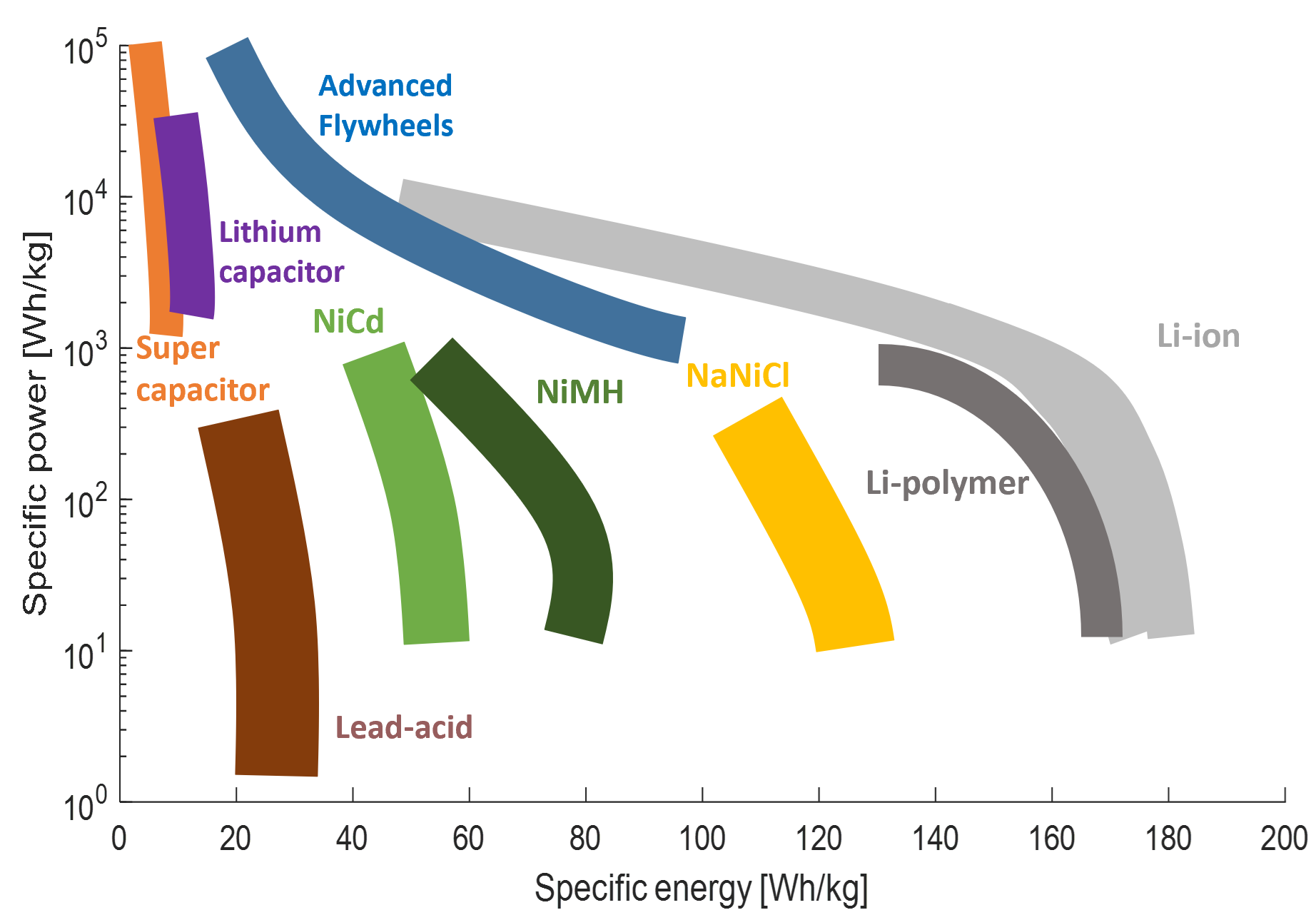
3.1.2. Power Sources

In an HD FCEV, the power for propulsion and auxiliary loads may be supplied solely by the fuel cell system (FCS) or a combination of FCS and one or more onboard energy storage systems (ESS, e.g., electrochemical battery, supercapacitor, flywheel), to support overall efficient powertrain as well as FCS functioning, response, drivability, good cold start characteristics, operation under extreme scenarios and FCS-ESS lifetime extension depending on the nature of usage [75]. Aiming for fuel savings and longevity, the trend in modern-day electrified heavy-duty (HD) applications has been to run the complete HV electrical system around 650 or higher voltage levels to support the efficient operation of different subsystems under high power demands [76]. For long-haul applications, the FCS is generally sized as the primary power source and converts chemical energy stored in the onboard hydrogen fuel along with oxygen from the ambient air into DC electrical power for running the traction and auxiliary loads through the DC bus link [77]. The presence of a secondary ESS can be important for such applications to optimise the functioning of the FCS and the energy management of the complete vehicle through the efficient collective operation of different subsystems. Even though supercapacitors and flywheel systems offer higher specific power and could efficiently support transient high load demands, electrochemical batteries are currently the most preferred ESS solution due to their suitability for matching HDV specific power, energy, robustness, response and costs requirements [78][79]. Among other electrochemical battery technologies such as lead-acid, nickel-cadmium (NiCd), nickel metal hydride (NiMH), and sodium–nickel–chloride zebra (NaNiCl), Li-ion cells offer the highest performance and widest choice of specific power to specific energy balance and are the current preference from a price-performance perspective (Figure 2[80]. For applications with the plug-in electric-only operation, an onboard charger can also be included for directly charging the battery in case of an external alternating current grid supply or for stepping down and controlling battery charging voltage from external direct current supply [59][60].
Comparison of specific power and specific energy capacities for different energy storage systems (ESS): electrochemical batteries, supercapacitors and flywheels
Figure 2. Comparison of specific power and specific energy capacities for different energy storage systems (ESS): electrochemical batteries, supercapacitors and flywheels [81][82][83].

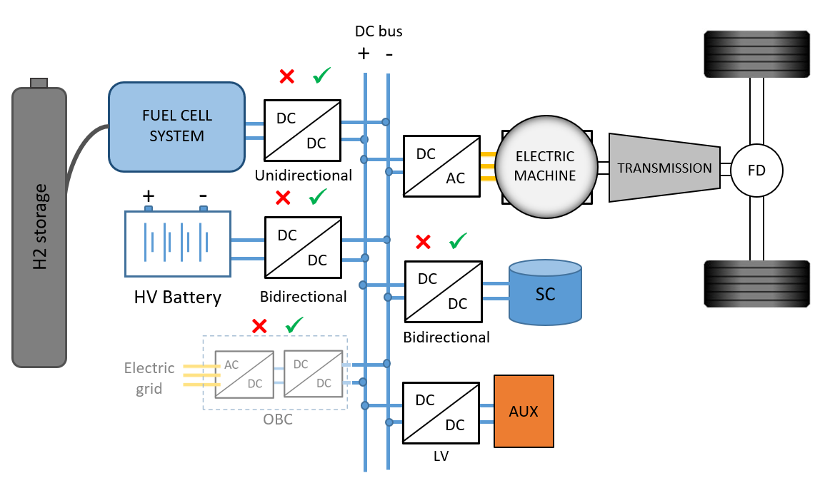
3.1.3. DC Link and Converter Combinations

The different power sources (e.g., FCS, HV battery, SC, onboard charger) and loads (e.g., eDrive, LV auxiliaries, power take-off) are usually interconnected through a common high voltage (HV) DC bus whose voltage level is regulated to conduct efficient power generation, traction, charging, braking energy recuperation, reuse and auxiliary load operation while following various energy management strategies [84]. High power output and efficient operation of the eDrive can be assured by maintaining a constant desired level of DC bus voltage supply to the eDrive (350 V–800 V for HD) [76][85]. Regulating DC bus voltage in plug-in charging can also precisely control the C-rate and corresponding charging power to the HV battery, extending its lifetime. A combination of various DC/DC converter configurations between power sources (e.g., FCS, HV battery and SC), loads (e.g., eDrive, auxiliaries) and the DC bus are generally used to achieve such a degree of freedom over bus voltage regulation supporting desired subsystem operations and powertrain control strategies at the expense of added power electronics converter costs [75][86][87]. On the other hand, if there is no DC-DC conversion between the power sources (FCS, ESS) and the eDrive, the electrical motor efficiency can be severely affected during high load demands or low SoC due to field weakening from lowered DC bus voltage. Besides, in the absence of a DC-DC converter in such situations, even adjusting phase current magnitude is unable to fulfil the requirements on eDrive torque and power during high-speed operation and cannot operate at the maximum constant power curve. Therefore, at higher rpm, there is a sharp rise in motor and inverter losses in the eDrive in the absence of DC-DC conversion [88].
With the FCS being an irreversible energy source operating at a largely varying load-dependent terminal voltage and generally being assembled for slightly lower stack voltage level due to mechanical construction limitations, a uni-directional HV DC/DC boost converter is used to interface it with the DC bus [1][89]. In [90], several competitive topologies for FCS DC voltage conversion have been analysed and reviewed. It has been found that the multi-phase interleaved boost converter is suitable for automotive DC bus applications up to 800 V among different non-isolated DC/DC converter topologies due to their capability to (a) provide controlled DC bus voltage with reduced FC stack current ripple to avoid damage and ageing, (b) manage the high current stress by distributing it between phases, (c) redundancy during power switch faults and (d) reduced electrical stresses on the power semiconductors [91][92]. A bidirectional HV DC/DC converter can be used to connect the onboard energy storage (i.e., battery or SC) with the DC bus to maintain its desired voltage level and efficient eDrive operation irrespective of the varying ESS states (i.e., SoC, temperature, current draw and ageing) [85][93][94]. Using a bidirectional DC/DC converter, the HV battery pack may also be sized to operate at lower voltages to reduce component costs and improve redundancy [86]. A smaller DC bus capacitor is connected in parallel to the DC link to absorb high frequency and high power transient load demands, respectively, limiting voltage ripples for maintaining greater operating efficiency of major power sources and loads [89][95]. From the review article analysis [90], it can be concluded that interleaved bidirectional converter is the most suitable converter topology for power above 10 kW, thanks to its (a) low input current ripple, (b) simple control, (c) fast response during transient loads and (d) redundancy during power switch faults.
In terms of power electronics switch materials for DC/DC and DC/AC converters, evolution has been from traditional silicon-based semiconductors (Si) towards wide band gap devices such as silicon carbide (SiC) and, in specific cases, gallium nitride (GaN) due to higher thermal conductivity, operating voltage, electron mobility, saturation velocity and low leakage current for building compact, high power and more efficient power converter systems [96].

3.1.4. Auxiliary Loads

The electrified nature of the FCEV powertrain also promotes electrically operated auxiliary loads, including cooling pumps and fans, HVAC compressor and blower, power steering, pneumatic systems and motorized power take-off (PTO) along with lighting and comfort systems [97][98][99]. Even after accounting for the higher electrical conversion losses compared to the mechanically driven loads, these actuators benefit from prime mover free operation. They can thus run at high efficiency irrespective of the prime mover operation to satisfy the varying temperature, pressure and other optimal predictive state targets while reducing overall system losses by 5–15% [100][101][102][103]. An LV DC/DC converter is required to step down voltage from the HV DC bus to 24 V to supply auxiliary loads and electronic control units (ECU) that run on the traditional 12 V/24 V systems. A 48 V DC/DC conversion may be more suitable for higher power auxiliary loads such as PTO, power steering and air compressor while maintaining safety and good operating efficiency [76]. Full-bridge, dual-active bridge, resonant converter or triple-active bridge converter topologies are preferred candidates for LV DC/DC conversion due to their soft-switching properties, lower electromagnetic interference, bidirectional power flow, large current handling capacity (up to 25 A), lower passive count, compact size and higher reliability [104][105]. With the advent of autonomous driving and sensor fusion technologies, the auxiliary load power consumption is assumed to increase further in the near future [76].

3.1.5. On-Board H2 Storage

Hydrogen fuel features high specific energy (gravimetric density), but low volumetric density as compared to conventional liquid fuels and even electrochemical batteries, making their onboard storage a challenge from the available space, vehicle length regulations and aerodynamics perspective [106]. Hydrogen fuel is usually stored under pressure in composite fuel tanks to manage vehicle size for favourable payload capacity and low drag resistance [18]. Overall, 350 bar is currently the most preferred storage pressure (16 gH2/L [107]) primarily limited by the capabilities of the refuelling infrastructure, cost of storage tanks and available fuelling stations, although modern examples with 700 bar as seen in the HECTOR project (27 gH2/L [107][108]) and even liquefied hydrogen storage (36 gH2/L [107]) are being considered, which should further help in lowering the traction energy requirement while improving payload capacity and refuelling time [109][110]. Kast et al. have analysed the feasibility of FCEV powertrain integration for various US HDV classes and have shown that 350 bar onboard storage for most possible journeys can be easily accommodated using the space behind the driver cabin, as seen in different use cases [111]. However, there is a greater challenge for European trucks where the allowed dimensions are more restrictive. To further improve the capacity of onboard volumetric storage over pressurised tanks, H2 gas may be liquefied or carried in a highly cooled cryogenic compressed form (300 bar, −150 to −240 C) as seen in the upcoming Daimler GenH2 truck presented at IAA 2022 (which includes two tanks of a total of 80 kg liquefied hydrogen), and in the CRYOGAS initiative by Clean Logistics Germany. These vehicles aim at further extending the range of hydrogen trucks to 1000 km with a refuelling time of as low as 10 min [112][113]. Basma et al. have analysed and indicated that for particularly long-distance applications, compressed H2 storage behind the driver cabin might require shifting of the fifth wheel backwards which, given the maximum loading capacity of the drive axle, could lead to a loss in the maximum load carrying capability [114]. Metal hydride storage offers over 2.5 times the volumetric energy density of 700 bar compressed H2 tanks. However, it can be less safe, slow and inefficient due to endothermic and exothermic hydrogenation and dehydrogenation reactions requiring complex onboard thermal management strategies [115]. Rivard et al. have compared compressed, liquefied, cooled cryogenic compressed and metal hydride along with metal–organic frameworks, carbon nanostructures and Kubas-type advanced H2 storage techniques and have stated compressed hydrogen as the leading future industry standard [115]. Apart from a detailed review of various onboard storage methods, Baetcke et al. have also compared filling rate, well to prime mover efficiency, storage system and infrastructure costs, current and future development status and market aspects of these techniques [116]. The details of various current onboard H2 storage techniques for long haul HDVs have been listed and compared in table below (Table 1).
Table 1. Comparison of various H2 fuel onboard storage techniques for long-haul heavy-duty road mobility [115][116]
Method Volumetric Density [gH2/L]  Gravimetric Density [gH2/kg]  Pressure [bar]  Temperature [◦C] 
Compressed 350 16 55 350 Ambient
Compressed 700 27 57 700 Ambient
Liquid 36 75 1 to 70 -253 to -244
Cryo compressed 72 55 300 -150 to -240
Metal hydride (NaAlH4) 70 35 20 260 to 425
Metal hydride (LiBH + MgH2) 80 80 - -
Metal borohydride (AL(BH4)3) 70 100 105 -140
Liquid organic hydrogen carrier 56 65 Ambient Ambient
Metal organic framework 13 50 1 to 350 -203 to ambient

3.2. HD 40T Fuel Cell Truck Simulation and Energy Audit

To further understand the functioning of a typical HD FCEV powertrain, the current case study analyses and compares powertrain operation, H2 fuel consumption, overall energy expenditure and losses across various subsystems, traction and auxiliary loads for a 40-tonne fuel cell truck running on VECTO Regional delivery and Longhaul drive cycles. The results are generated from the simulation of the vehicle use case on an in-house distance-based forward powertrain model that uses a combination of dynamic and data-driven approaches for representing various vehicle subsystems. Equivalent consumption minimisation strategy (ECMS) based energy management with auxiliary loads, including varying cooling system, HVAC and onboard electrical consumption, were considered for this analysis. The current powertrain configuration includes a DC/DC boost converter for the FCS interface, whereas the HV battery (ESS) is directly connected to the DC bus.
For an approximately similar travelled distance (100 km), driving on the VECTO Longhaul cycle showed lower H2 consumption due to the higher overall tank-to-wheel (TTW) powertrain efficiency even though higher traction energy was consumed. Out of this total traction energy, 40.9% and 45% were consumed by aerodynamic drag, 58.3% and 54.8% was consumed by rolling resistance, and 0.9% and 0.2% were given against road gradient for VECTO Regional delivery and Longhaul cycles due to their speed, duration and gradient characteristics, respectively (Figure 3). A significant part of the total fuel energy was dissipated in friction brakes for the Regional delivery cycle than for the Longhaul cycle (3.45% against 1.9%) due to the higher number of intensive stopping events surpassing the regenerative braking capability of the eDrive. eDrive and drivetrain (transmission) contributed to 7.4%, 6.5% and 3.9%, 3.6% of the total fuel energy losses for the Regional delivery and Longhaul drive cycles, respectively. Auxiliary load consumption (comprising the cooling system, HVAC and onboard electrical systems) for Longhaul (1.4%) was less than for the Regional delivery cycle (2%), mainly due to the higher average speed leading to shorter travel time (continuous onboard electrical losses) and more importantly a lower cooling system and HVAC consumption due to higher airspeed (efficient heat evacuation). The loss contribution of the HV battery pack from the overall fuel energy was also less for Longhaul than for the Regional delivery cycle due to the nature of transient start–stop power demand and the ECMS energy management strategy. On the other hand, FCS losses for the two cycles were almost the same.

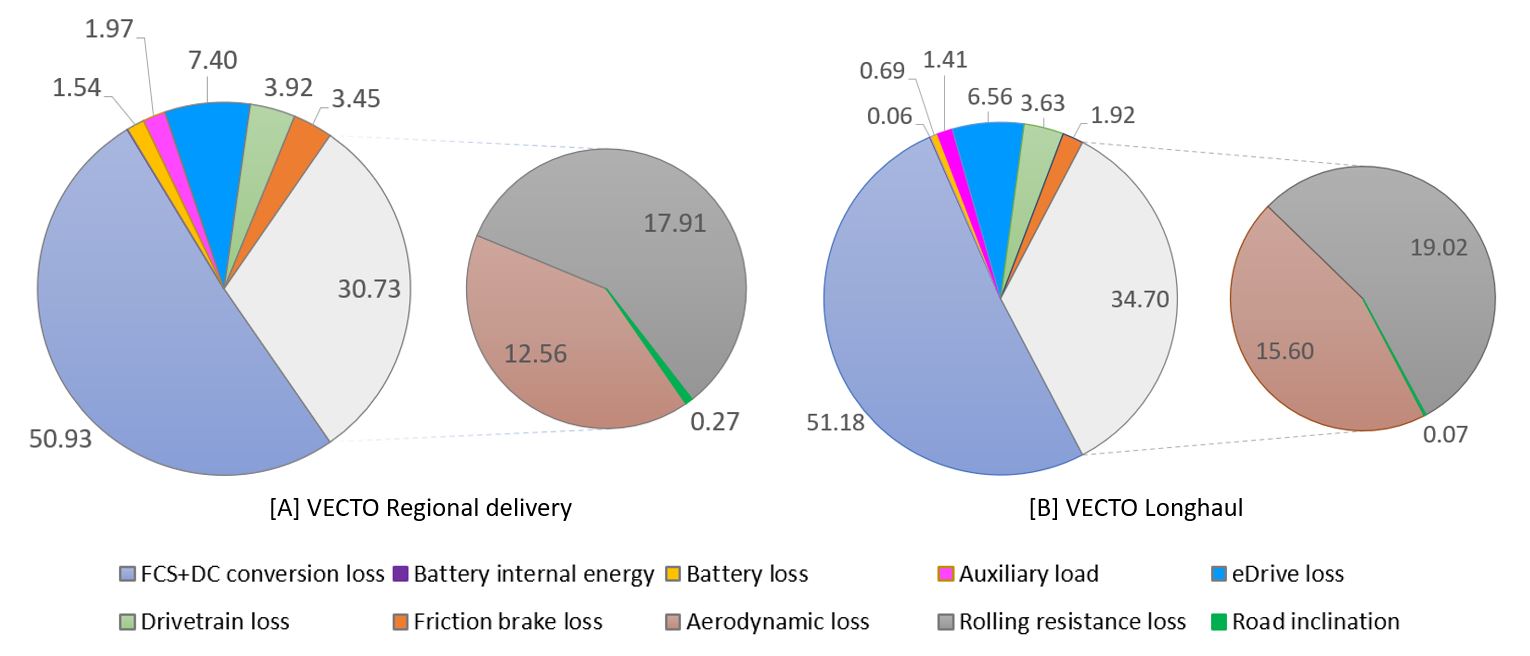
Figure 3. Percentage distribution of H2 fuel energy expenditures and losses among different powertrain subsystems and driving resistances for 40-tonne fuel cell truck running on (A) VECTO Regional Delivery and (B) Longhaul drive cycles. 

3.3. Fuel Cell System—Balance of Plant

Individual fuel cells (FC) are connected in series to form a stack for increasing the overall terminal voltage to meet application-specific power requirements [1][117]. The number of cells that can be connected in series tends to be limited by the mechanical constraints of the assembly, curbing the possible terminal voltage of the fuel cell stack [27][89]. Multiple fuel cell stacks or systems can also be run in parallel to increase the power output to the desired level by increasing the effective active surface area while respecting FC current density limits. Such multi-stack assemblies could also be run sequentially to improve part load FCS efficiency while satisfying peak power demands, improving thermal management and functional safety [118][119]. Choosing the right configuration of series connected cells and parallel cell strands can be important for maintaining high system operating efficiency since the stack can experience a voltage drop of up to 50% during full load operation [27][120]. Bipolar plates shown serve to maintain electrical contact between opposite electrodes of series stacked fuel cells, distribute H2 and air uniformly across cell surfaces, and effectively cool individual membrane assemblies by housing coolant channels [27][121]. The fuel cell stacks are supported by various auxiliary components for maintaining functional safety, desired power output, good system efficiency, response, operability in extreme ambient conditions and extending service life, which are together known as balance of plant (BoP) components (Figure 4 and Figure 5) [122][123][124][125]. Power is also consumed in running these BoP components (PBoP) decreasing the output efficiency of the FCS (ηFCS) from that of the fuel cell stack. Here, PFC is fuel cell stack power, dmH2 is mass flow rate of H2 fuel and LHVH2 is the lower heating value of H2 fuel.
Figure 4. Balance of plant subsystems supporting functioning of the fuel cell stack include air, fuel and thermal management systems.
/media/item_content/202301/63b7843d759f4energies-15-09557-g009.png

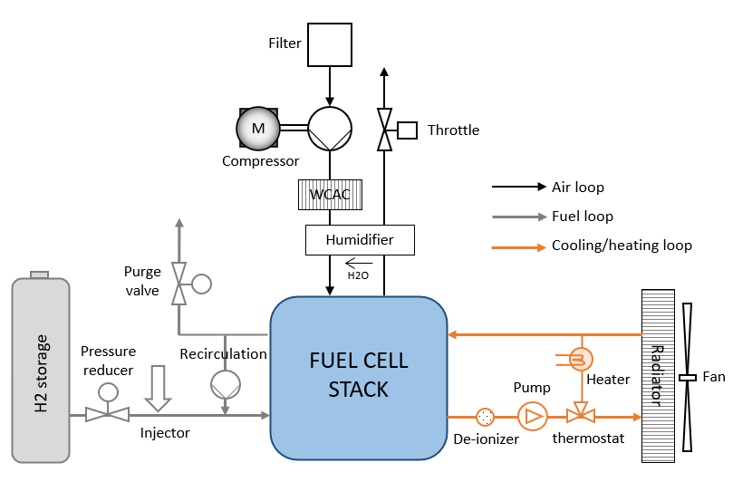
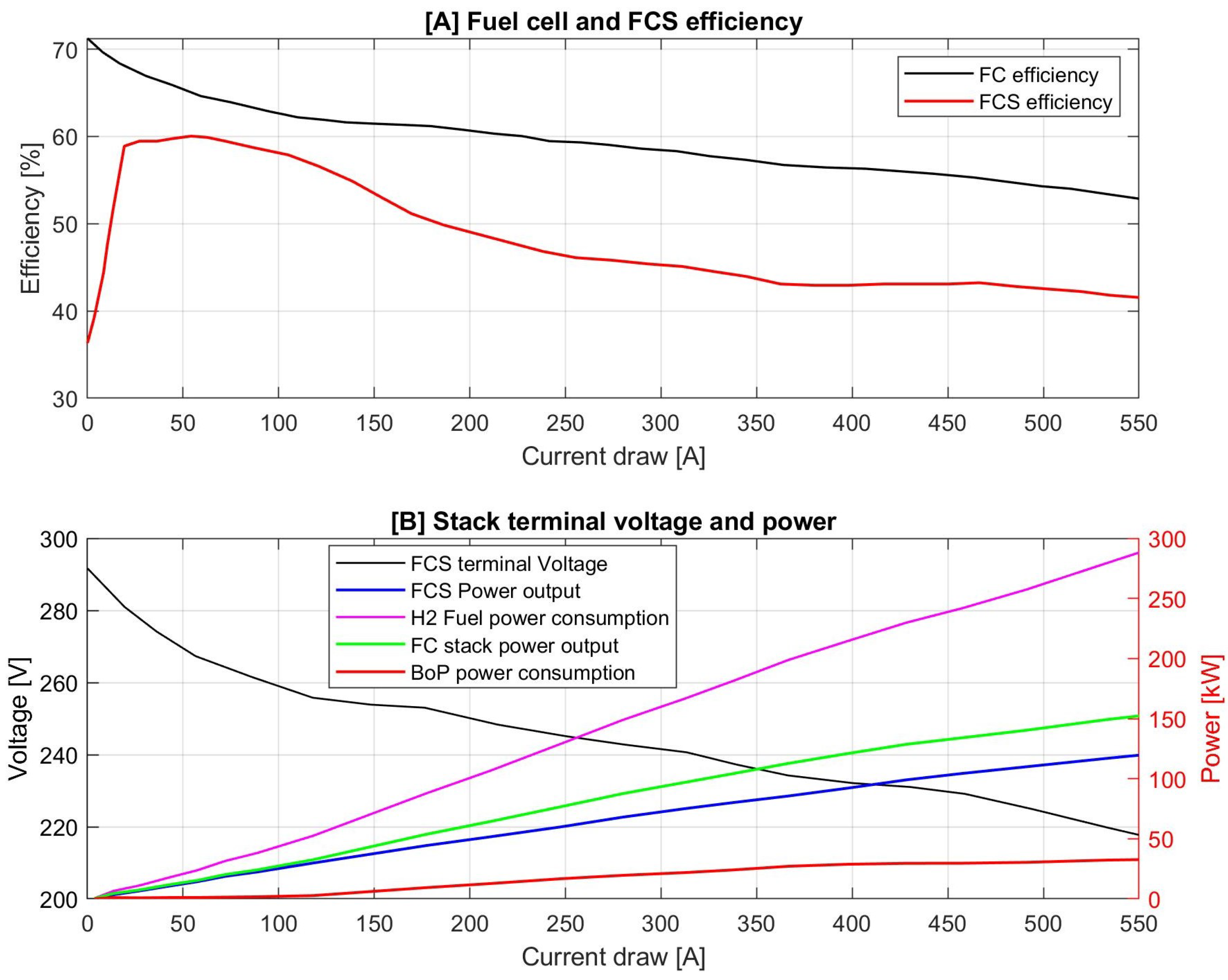
Figure 5. (A) Fuel cell stack and fuel cell system energy conversion efficiencies based on current draw inspired from Toyota Mirai 2 bench-marking tests performed by AVL and FEV, (B) corresponding stack terminal voltage drop and FCS, FC stack, BoP components, H2 fuel power [117][126]

3.3.1. Effect of Temperature, Pressure and Humidity

Higher FC temperature generally improves performance and efficiency but may lead to membrane dehydration and degradation of catalyst layer [127][128]. FC power and efficiency based on voltage polarisation curve and current density improve with increased electrode pressure due to higher reactant partial pressures and enhanced membrane conductivity from increased water content [129][130]. However, this pressure can also elevate the permeability of the membrane leading to H2 and O2 crossover, water management issues and an increase in BoP parasitic losses [129][131]. Low relative humidity across electrodes can cause decreased reaction rates, lowered ionic conductivity, reduced mass diffusion rate across the membrane and increased flow resistance leading to a reduction in FC efficiency and power output (lowered V-I polarisation curve and limited maximum current density) [132][133]. On the other hand, the presence of excess water can block porous channels of the gas diffusion layer, hindering mass diffusion and covering cathode side catalytic active areas inhibiting conversion reactions, that lead to a reduction in performance, efficiency and FC lifespan [134]. Water management is especially required at high load as excessive cathode water formation may lead to cathode catalyst oxygen starvation [135]. While reducing gas flow rate and performance, overflow of cathode water towards anode side can also cause temperature unevenness across the anode surface, oxidising the catalyst area and corroding the carbon support. The BoP components forming air system, H2 fuel system and thermal management system are thus aimed at regulating pressure, relative humidity, reactant concentrations and temperature across FC electrodes towards high performance, efficiency and longevity of the subsystem. The INN BALANCE project supported by Fuel Cells and Hydrogen Joint Undertaking and funded by the European Commission aims at development of advanced fuel cell BoP components in terms of high efficiency, reliability, technology maturity and lower costs [136].

3.3.2. Air System

Oxygen in the ambient air is used by the cathode side to react with hydrogen protons crossing the membrane electrolyte assembly (MEA), generating electrode potential and water. Air for cathode feed first passes through an air filter to remove dust, soot particles and other harmful agents to avoid FC poisoning. Intake air then gets boosted by the compressor to achieve the desired cathode pressure and mass air flow while also maintaining the proper air-fuel excess ratio λ. Fuel cell conversion efficiency and performance have high sensitivity to cathode side oxygen partial pressure and stoichiometry, usually requiring running in oxygen excess mass flow [137][138]. Depending on the range of FC current drawn, Chen et al. have shown a range of 3 to 2.25 air excess ratio as the optimal while avoiding starvation and maintaining high efficiency on their experimental FC setup and control oriented third order model [139]. Air compressor also tends to consume the highest auxiliary load among the BoP components [27]. Boosting too much air into the cathode may increase power output, but costs even higher BoP parasitic losses, lowering FCS efficiency [140][141]. Maintaining the right cathode partial pressure and stoichiometric intake air ratio during high load-high mass flow operation can be a challenge from design/control limitations of the air system leading to a compromise on FC efficiency and cathode side starvation [58]. Thus, the right cathode partial pressure, stoichiometric intake air ratio and mass air flow must be regulated while maintaining membrane durability and low parasitic loads using a combination of compressor and exhaust throttle value operation. A charge air cooler is used to lower the elevated temperature of boosted air (>150 C) to acceptable levels for protecting the FC membrane and humidifier while also improving air path efficiency [114]. For efficient proton exchange, the FC membrane (MEA) must be appropriately humidified [27]. Water vapour generated at the cathode exhaust exit air is used to humidify the cathode inlet air flow using a humidifier device. At the same time, a high amount of water accumulation in the cathode (flooding) can inhibit the active platinum sites decreasing the efficiency and performance of the fuel cell (oxygen starvation). The right amount of cathode humidity is thus another crucial control parameter of the air system [142]. Application of external cathode humidification circuit and humidifier device can be avoided through internal self humidification mechanisms, thereby lowering FCS volume and weight as seen in the current Toyota Mirai 2 use case [143]. Through opposite flow of anode H2 and cathode air in the FC, increased H2 recirculation and application of a thinner membrane, sufficient and even back diffusion of water coming to the anode back to the cathode can be maintained, evenly humidifying the inlet cathode air and making deletion of the external humidifier possible [143].

3.3.3. Fuel System

Hydrogen fuel stored inside high-pressure tanks (350–700 bar) is expanded and supplied at the anode using a pressure reducer valve and an injector to avoid excessive anode pressure gradient and damage across the FC membrane [27][114]. With a need for low-pressure injection, the use of a fuel pump is usually avoided to minimize auxiliary loads and instead, energy from the pressurized storage tank is directly used to inject fuel into the system, requiring a minimum quantity of H2 to be left in the fuel tank before refuelling to maintain sufficient operation pressure. Due to the accumulation of diffused nitrogen and excessive water collection (flooding) from across the MEA, anode gases have to be purged regularly to maintain an acceptable H2 partial pressure on the anode side supporting good FC reactivity, performance and efficiency while also avoiding uneven humidification [144]. This situation is usually handled through bleed, dead-end, purge, recirculation or combined type fuel system operations [145]. A recirculation system may be used to avoid loss of hydrogen in these purges by reusing the excess hydrogen from anode exit as inlet fuel [114][146]. Apart from improving system efficiency by avoiding fuel loss, the H2 recirculation system may also be used for other purposes such as the above mentioned internal cathode self-humidification mechanism. Anode H2 recirculation may be done actively using a recirculating pump, blower or passively using ejector valves [145]. With the active method, the fuel return rate can be precisely controlled according to the operating situation of the FCS, giving a higher degree of control freedom at the expense of added parasitic losses. Using passive ejectors, much higher FCS efficiency can be obtained while the component design has to be adapted, especially the specific FC stack [147].

3.3.4. Thermal Management System

Thermal management of the fuel cell system is carried out by a cooling loop consisting of a radiator heat exchanger, a pump for circulating the coolant to and from the radiator and a fan to blow air over the radiator, improving heat rejection [148]. Even with better conversion efficiency, the cooling system of the FCS has to be much larger than that of conventional ICE, as most of the heat loss is rejected to the FCS body, whose operating temperature also needs to be lower (80 C), further lowering the possible heat transfer [149]. Due to the issue of ice formation and poor fuel cell performance at cold temperatures, an electrical heater may also be employed in the cooling loop to help with quick heat-up during sub-zero cold starts [126]. A deionizer filter may also be installed in the cooling loop to avoid short circuits through the coolant water [150].

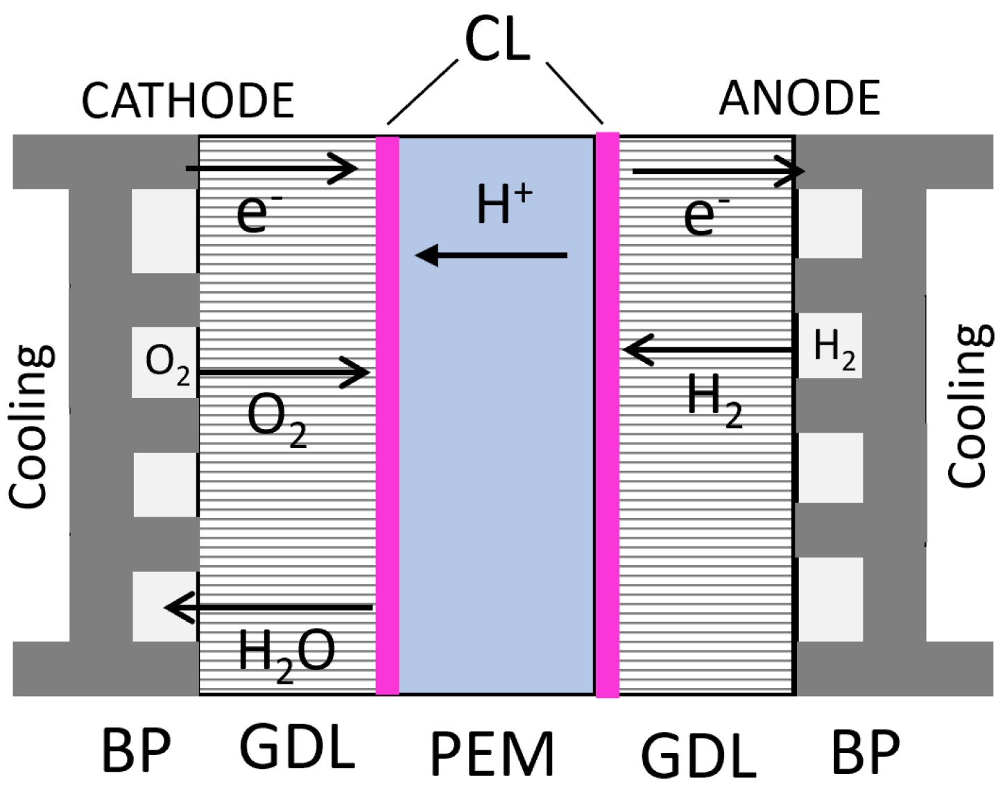
3.4. Proton Exchange Membrane Fuel cell

Fuel cells (FC) can be defined as electrochemical devices that convert chemical potential energy stored in the fuel (usually hydrogen) into DC electrical energy by reacting with ambient or onboard stored oxygen [151]. The by-products of such a reaction are water and heat loss, which need to be evacuated from the fuel cell assembly for its proper functioning [152]. Total decoupling of the power generation and energy storage is thus possible, giving a substantial scope for improving these aspects over modern-day closed electrochemical battery cells [1][19]. Depending on the used fuel (hydrogen carrier), cell voltage range, operating temperature range and typical applications, fuel cells can be classified as polymer electrolyte membrane (PEMFC), alkaline (AFC), phosphoric acid (PAFC), molten carbonate (MCFC), solid oxide (SOFC) and direct methanol (DMFC) type open cells [153][154][155]. Among these fuel cell technologies, the operating temperature can range between 60–1000 C [152]. Considering the impetus on compressed hydrogen (H2) as the future fuel for long-haul HD sector decarbonisation, suited operating temperature range (80 C), corresponding fast start-up time, high power density, durability, technology maturity, and cost, the proton exchange membrane (PEM) technology is currently being considered as the most viable fuel cell solution and will now be discussed in detail [1][27]. The PEM FC is an open electrochemical cell and requires a continuous supply of hydrogen and oxygen at regulated pressure, temperature and humidity for efficient operation [27][138].
Hydrogen is supplied at the anode side by the bipolar plate (BP) and travels through the gas diffusion layer (GDL) to the catalyst layer (CL). On contact with platinum-based active material at the CL, it splits into hydrogen protons and electrons through the hydrogen oxidation reaction (HOR). The proton exchange membrane (PEM) allows for the transfer of only the hydrogen protons while the electrons are transported to the cathode side through an external electrical circuit [27]. On the cathode side, oxygen (O2) is supplied by the BP, which travels through the GDL and reacts with hydrogen protons coming from the PEM and externally transported electrons at the CL through oxygen reduction reaction (ORR). Water molecules are generated, which need to be evacuated back through the GDL and BP. The electro-potential formed across the anode and cathode from HOR and ORR sub-reactions can force the transported electrons across the electrical load, generating DC electrical power (Figure 6). In the fuel cell stack, the BP form a back-to-back electrical contact between the fuel cell pair anode and cathode, and also hold the cooling channels for FC thermal management. The assembly of BPs, GDLs, CLs and PEM forming the fuel cell unit are together known as the membrane electrolyte assembly (MEA) (Figure 7).
/media/item_content/202301/63b784ba07bcdenergies-15-09557-g011.png
Figure 6. Proton exchange membrane fuel cell hydrogen oxidation and oxygen reduction reactions (HOR and ORR) at anode and cathode generating electropotential across the external electrical load.
/media/item_content/202301/63b784a5ab32fenergies-15-09557-g012.png
Figure 7. Fuel cell membrane electrolyte assembly (MEA) comprising of bipolar plates (BP) with cooling channels; gas diffusion layer (GDL); catalyst layer (CL); and proton exchange membrane (PEM) along with corresponding ion transport mechanism [156].

3.5. Fuel Cell Ageing

Given the expected fourfold lifetime mileage of long-haul HD FCEVs compared to light-duty applications, maintaining system durability and performance by minimising FCS ageing is highly important for integrating fuel cell technology in the HD sector [157]. As explained, FCS ageing will affect not only performance and efficiency, but also the cooling requirement and, thus, auxiliary energy consumption. As a part of the GIANTLEAP project, Zeljko et al. have discussed several degradation mechanisms of PEMFC for HD applications [58]. They have listed mechanical, thermal and chemical degradation of the membrane, activation, conductivity, mass transport rate, water management losses of the CL, contamination, mass transfer and water management loss of the gas diffusion layer and sealing gasket and bipolar plate failures along with conductivity loss as the main ageing mechanisms and have detailed the corresponding mechanical, thermal, chemical contamination, corrosion and humidity-related causes. Ageing mechanisms of BoP components, especially air compressor and humidifier, and mitigating strategies for extending FCS lifetime were also highlighted [158]. By quantifying the time scale of accelerated single fuel cell degradation test results with long-term stack level degradation rate, ageing models were proposed [159]. Ferrara et al. have also listed critical FC degradation phenomena such as carbon support corrosion, mechanical, catalyst, chemical and membrane type degradation arising from temperature and humidity non-uniformity, reactant starvation, potential cycling, air/H2 boundary distribution, sub-zero temperature operation, reactant crossover and high-temperature operation. These conditions are highly linked with frequent start-up/shut-down cycles, transient load variations, and very low and high power operation of the FCS [160]. Mayur et al. have modelled and compared transient load sensitive degradation of FCS due to flow field dependant non-uniform distribution of reactants across FC surface causing platinum dissolution at low load and spatial catalyst dispersion at high load on different mission profiles [161]. Through experimental results using segmented cell technology, Lin et al. have confirmed increased fuel cell degradation under transient driving cycles with a pronounced performance drop at high current density [162]. Using 3D ageing model simulation, Karpenko-Jereb et al. have shown that the FC current density decay is non-uniform and depends on local temperature, relative humidity, voltage and gas concentrations across the active surface area of the cell [163]. In case of FC dehydration over a long period of time, the MEA shows degradation with the crystal structure of the membrane being destroyed to an extent and the electrochemical activity of the membrane being affected [164]. Pathways for mitigating FCS ageing can be classified into three categories: component design optimisation at the FCS product development level, ageing mitigating strategies at the FCS operation level and hybrid strategies at the complete FCEV powertrain level.
  • Design changes in the inlet flow field, air-fuel system and the MEA structure can lower non-uniformity of humidity, reactant concentration, temperature and pressure across FC surface under extreme operating conditions such as rapid transients, sub-zero cold starts, very low and high load. In terms of materials, membrane reinforcement by polytetrafluoroethylene binder (PTFE) has been shown to improve FC lifetime. Chemical and electrochemical performance could be extended by incorporating inhibitors, free-radical stabilisers and sacrificial materials in the membrane. Platinum dissolution can be lowered by changing the CL design and using Pt-based compounds. By changing the design of PTFE and ionomer using water-blocking components, water retention can be improved on the anode side to lower carbon corrosion issues. Increasing the PTFE content can also improve the water management ability of the GDL. Coating with noble metals, nitrides or carbide-based alloys is the current subject for bipolar plate ageing mitigation. However, the coating can lead to reduced mechanical strength and fractures under high load, especially under repeated thermal cycling, and is a subject of current research [158].
  • By using intelligent control strategies at the FCS level, flow field non-uniformity can be further lowered by preparing the FCS for immediate operating events, especially under transient driving conditions in terms of humidity, boost pressure, electrode reactant concentrations, preconditioning of BoP components, etc. Membrane reliability can be improved by maintaining high relative humidity and water content, especially at the reactant inlets. The durability of the CL can be improved by maintaining appropriate conditions such as relative humidity and low temperature throughout the operation [158].
  • The effect of transient driving, sub-zero cold starts, very high and low load operation can be further lowered by regulating the load demand from the FCS in different parts of the drive cycle using the added degree of freedom from the hybridised FCEV powertrain. This will include the usage of OTA predictive route information to estimate upcoming FCS ageing-inducing situations and preparing the ESS state of energy, temperature and FCS reactant concentrations, humidity, temperature, pressure for these events.

References

  1. Bethoux, O. Hydrogen Fuel Cell Road Vehicles: State of the Art and Perspectives. Energies 2020, 13, 5843.
  2. Ruf, Y.; Baum, M.; Zorn, T.; Menzel, A.; Rehberger, J. Fuel Cells Hydrogen Trucks—Heavy-Duty’s High Performance Green Solution. Fuel Cells and Hydrogen 2 Joint Undertaking. 2020. Available online: https://www.rolandberger.com/en/Insights/Publications/Fuel-Cells-Hydrogen-Trucks.html (accessed on 2 December 2022).
  3. Ambel, C.C. Too Big to Ignore—Truck CO2 Emissions in 2030. Transport and Environment. 2015. Available online: https://www.transportenvironment.org/discover/too-big-ignore-truck-co2-emissions-2030/#:~:text=Emissions%20from%20heavy%2Dduty%20vehicles,of%20all%20EU%20CO2%20emissions. (accessed on 2 December 2022).
  4. European Commission. Reducing CO2 Emissions from Heavy-Duty Vehicles. Available online: https://ec.europa.eu/clima/eu-action/transport-emissions/road-transport-reducing-co2-emissions-vehicles/reducing-co2-emissions-heavy-duty-vehicles_en#ecl-inpage-530 (accessed on 2 December 2022).
  5. European Commission. EU Regulation 2019/1242 Setting CO2 emission performance standards for new heavy-duty vehicles and amending Regulations (EC) No 595/2009 and(EU)2018/956 of the European Parliament and of the Council and Council Directive 96/53/EC. Off. J. Eur. Union 2019, 202–239.
  6. Clean Technica. Green Trucking Watershed Moment as EU Adopts New Tolling Rules. Available online: https://cleantechnica.com/2022/02/17/green-trucking-watershed-moment-as-eu-adopts-new-tolling-rules/amp/ (accessed on 2 December 2022).
  7. Becker, H.; Bichucher, V.; Dwyer, J.; Engstrom, S.; Farrag-Thibault, A.; Hamdi-Cherif, C.; Heid, B.; Hertzke, P.; de Monts, A.; Östgren, E.; et al. Road Freight Global Pathways Report. Available online: https://www.mckinsey.com/industries/automotive-and-assembly/our-insights/road-freight-global-pathways-report (accessed on 2 December 2022).
  8. International Energy Agency. Tracking Transport 2021. Available online: https://www.iea.org/reports/tracking-transport-2021 (accessed on 2 December 2022).
  9. Transport Decarbonisation Alliance; C40; POLIS. Zero-Emission Zones—Don’t Wait to Start with Freight! How-to Guide Zero-Emission Zones. 2020. Available online: https://www.polisnetwork.eu/wp-content/uploads/2020/10/4_MOMOB_ReVeAL-Dynaxibility-Freight.pdf (accessed on 2 December 2022).
  10. Cui, H.; Gode, P.; Wappelhorst, S. A Global Overview of Zero-Emission Zones in Cities and Their Development Progress. International Council on Clean Transportation report. 2021. Available online: https://theicct.org/publication/a-global-overview-of-zero-emission-zones-in-cities-and-their-development-progress/ (accessed on 2 December 2022).
  11. Sandy Thomas, C. Transportation options in a carbon-constrained world: Hybrids, plug-in hybrids, biofuels, fuel cell electric vehicles, and battery electric vehicles. Int. J. Hydrogen Energy 2009, 34, 9279–9296.
  12. Chan, C.C. The State of the Art of Electric, Hybrid, and Fuel Cell Vehicles. Proc. IEEE 2007, 95, 704–718.
  13. Van de Kaa, G.; Scholten, D.; Rezaei, J.; Milchram, C. The Battle between Battery and Fuel Cell Powered Electric Vehicles: A BWM Approach. Energies 2017, 10, 1707.
  14. Wilkins, S. Challenges and Opportunities For Highly Electrified Heavy Duty Vehicles. Decarbonisation of Heavy-Duty Vehicle Transport: Zero-Emission Heavy Goods Vehicles TNO. 2020. Available online: https://www.scribd.com/document/525429500/Steven-Wilkins-Challenges-and-Opportunities-for-Highly-Electrified-Heavy-Duty-Vehicles-Public (accessed on 2 December 2022).
  15. Heid, B.; Martens, C.; Wilthaner, M. Unlocking Hydrogen’s Power for Long-Haul Freight Transport. Available online: https://www.mckinsey.com/capabilities/operations/our-insights/global-infrastructure-initiative/voices/unlocking-hydrogens-power-for-long-haul-freight-transport (accessed on 2 December 2022).
  16. Jung, S. A Sneak Peek at the Next-Generation Hydrogen Engine for Commercial Trucks. Available online: https://blog.ballard.com/hydrogen-engine (accessed on 2 December 2022).
  17. Verbruggen, F.; Hoekstra, A.; Hofman, T. Evaluation of the state-of-the-art of full-electric medium and heavy-duty trucks. In Proceedings of the 2018 World Electric Vehicle Symposium and Exhibition (EVS31), Kobe, Japan, 30 September–3 October 2018.
  18. Kast, J.; Morrison, G.; Gangloff, J.J.; Vijayagopal, R.; Marcinkoski, J. Designing hydrogen fuel cell electric trucks in a diverse medium and heavy duty market. Res. Transp. Econ. 2018, 70, 139–147.
  19. Bethoux, O. Hydrogen Fuel Cell Road Vehicles and Their Infrastructure: An Option towards an Environmentally Friendly Energy Transition. Energies 2020, 13, 6132.
  20. Tsakiris, A. Analysis of Hydrogen Fuel Cell and Battery Efficiency. World Sustainable Energy Days 2019, Young Energy Researchers Conference. 2019. Available online: https://c2e2.unepccc.org/wp-content/uploads/sites/3/2019/09/analysis-of-hydrogen-fuel-cell-and-battery.pdf (accessed on 2 December 2022).
  21. Ruf, Y. Study on European business cases for fuel cells and hydrogen trucks. In EU Hydrogen Week; Roland Berger GmbH: Munich, Germany, 2020.
  22. Edwards, P.; Kuznetsov, V.; David, W.; Brandon, N. Hydrogen and fuel cells: Towards a sustainable energy future. Energy Policy 2008, 36, 4356–4362.
  23. Cunanan, C.; Tran, M.K.; Lee, Y.; Kwok, S.; Leung, V.; Fowler, M. A Review of Heavy-Duty Vehicle Powertrain Technologies: Diesel Engine Vehicles, Battery Electric Vehicles, and Hydrogen Fuel Cell Electric Vehicles. Clean Technol. 2021, 3, 474–489.
  24. Miller, A. Applications—Transportation Rail Vehicles: Fuel Cells. In Encyclopedia of Electrochemical Power Sources; Garche, J., Ed.; Elsevier: Amsterdam, The Netherlands, 2009; pp. 313–322.
  25. Moriarty, P.; Honnery, D. Prospects for hydrogen as a transport fuel. Int. J. Hydrogen Energy 2019, 44, 16029–16037.
  26. Braga, L.B.; Silveira, J.; Silva, M.; Blanco Machin, E.; Pedroso, D.; Tuna, C. Comparative Analysis Between A Pem Fuel Cell And An Internal Combustion Engine Driving An Electricity Generator: Technical, Economical And Ecological Aspects. Appl. Therm. Eng. 2013, 63, 351–361.
  27. IFP School. Hydrogen for Mobility 2022. Available online: https://mooc.innovation.ifp-school.com/Training/view/227190 (accessed on 2 December 2022).
  28. Stępień, Z. A Comprehensive Overview of Hydrogen-Fueled Internal Combustion Engines: Achievements and Future Challenges. Energies 2021, 14, 6504.
  29. Lejeune, M. Decarbonized Powertrains for Road Freight. In Proceedings of the CNAM/SIA Conference Rational Use of Energy, Paris, France, 9 March 2021.
  30. Fayaz, H.; Saidur, R.; Razali, N.; Anuar, F.; Saleman, A.; Islam, M. An overview of hydrogen as a vehicle fuel. Renew. Sustain. Energy Rev. 2012, 16, 5511–5528.
  31. Robledo, C.B.; Oldenbroek, V.; Abbruzzese, F.; van Wijk, A.J. Integrating a hydrogen fuel cell electric vehicle with vehicle-to-grid technology, photovoltaic power and a residential building. Appl. Energy 2018, 215, 615–629.
  32. Oldenbroek, V.; Wijtzes, S.; Blok, K.; van Wijk, A.J. Fuel cell electric vehicles and hydrogen balancing 100 percent renewable and integrated national transportation and energy systems. Energy Convers. Manag. X 2021, 9, 100077.
  33. Yue, M.; Lambert, H.; Pahon, E.; Roche, R.; Jemei, S.; Hissel, D. Hydrogen energy systems: A critical review of technologies, applications, trends and challenges. Renew. Sustain. Energy Rev. 2021, 146, 111180.
  34. Schröder, M.; Abdin, Z.; Mérida, W. Optimization of distributed energy resources for electric vehicle charging and fuel cell vehicle refueling. Appl. Energy 2020, 277, 115562.
  35. European Commission, Directorate-General for Energy. A hydrogen strategy for a climate-neutral Europe. In Communication from the Commission to the European Parliament, the Council, the European Economic and Social Committee and the Committee of the Regions; European Union: Brussels, Belgium, 2020; pp. 1–24.
  36. Howarth, R.W.; Jacobson, M.Z. How green is blue hydrogen? Energy Sci. Eng. 2021, 9, 1676–1687.
  37. Lee, D.Y.; Elgowainy, A.; Kotz, A.; Vijayagopal, R.; Marcinkoski, J. Life-cycle implications of hydrogen fuel cell electric vehicle technology for medium- and heavy-duty trucks. J. Power Source 2018, 393, 217–229.
  38. Shamsi, H.; Tran, M.K.; Akbarpour, S.; Maroufmashat, A.; Fowler, M. Macro-Level optimization of hydrogen infrastructure and supply chain for zero-emission vehicles on a canadian corridor. J. Clean. Prod. 2021, 289, 125163.
  39. European Commission. Directorate-General for Mobility and Transport. Regulation Of The European Parliament And Of The Council on the deployment of alternative fuels infrastructure, and repealing Directive 2014/94/EU of the European Parliament and of the Council. Off. J. Eur. Union 2021, 1–181.
  40. European Commission. Research for TRAN Committee—Alternative Fuels Infrastructure for Heavy-Duty Vehicles—Final Study. Available online: https://www.europarl.europa.eu/thinktank/en/document/IPOL_ATA(2021)690902 (accessed on 2 December 2022).
  41. FuelCellsWorks. U.S. Senate Passes 1 Dollar Billion in Alternative Fuel Infrastructure, Including Hydrogen, EV and Natural Gas. Available online: https://fuelcellsworks.com/news/u-s-senate-passes-1-billion-in-alternative-fuel-infrastructure-including-hydrogen-ev-and-natural-gas/ (accessed on 2 December 2022).
  42. IRU. Joint Call for the Accelerated Deployment of Hydrogen Refuelling Infrastructure across the EU. Available online: https://www.acea.auto/files/Hydrogen_joint_call-ACEA_Hydrogen_Europe_IRU.pdf (accessed on 2 December 2022).
  43. AECA. Position Paper—Heavy-Duty Vehicles: Charging and Refuelling Infrastructure Requirements. Available online: https://www.acea.auto/publication/position-paper-heavy-duty-vehicles-charging-and-refuelling-infrastructure-requirements/ (accessed on 2 December 2022).
  44. Magnus, K.; Hans, P.; Anders, G.; Elna, H. Can Fuel Cells Become a Mass-Produced Option Globally for Heavy-Duty Trucks 2030+? Swedish Electromobility Centre Report. 2019. Available online: https://trid.trb.org/view/1737829 (accessed on 2 December 2022).
  45. Transport and Environment. Comparison of Hydrogen and Battery Electric Trucks. Available online: https://www.transportenvironment.org/wp-content/uploads/2021/07/2020_06_TE_comparison_hydrogen_battery_electric_trucks_methodology.pdf (accessed on 2 December 2022).
  46. Hunter, C.; Penev, M.; Reznicek, E.; Lustbader, J.; Birky, A.; Zhang, C. Spatial and Temporal Analysis of the Total Cost of Ownership for Class 8 Tractors and Class 4 Parcel Delivery Trucks. National Renewable Energy Laboratory Technical Report NREL/TP-5400-71796. 2021. Available online: https://www.nrel.gov/docs/fy21osti/71796.pdf (accessed on 2 December 2022).
  47. Thompson, S.T.; James, B.D.; Huya-Kouadio, J.M.; Houchins, C.; DeSantis, D.A.; Ahluwalia, R.; Wilson, A.R.; Kleen, G.; Papageorgopoulos, D. Direct hydrogen fuel cell electric vehicle cost analysis: System and high-volume manufacturing description, validation, and outlook. J. Power Source 2018, 399, 304–313.
  48. Marcinkoski, J.; Vijayagopal, R.; Kast, J.; Duran, A. Driving an Industry: Medium and Heavy Duty Fuel Cell Electric Truck Component Sizing. World Electr. Veh. J. 2016, 8, 78–89.
  49. Li, S.; Djilali, N.; Rosen, M.A.; Crawford, C.; Sui, P.C. Transition of heavy-duty trucks from diesel to hydrogen fuel cells: Opportunities, challenges, and recommendations. Int. J. Energy Res. 2022, 46, 11718–11729.
  50. Fragiacomo, P.; Genovese, M.; Piraino, F.; Corigliano, O.; Lorenzo, G.D. Hydrogen-Fuel Cell Hybrid Powertrain: Conceptual Layouts and Current Applications. Machines 2022, 10, 1121.
  51. Interreg. SYMBIO: Renault Maxity H2. Available online: https://fuelcelltrucks.eu/project/symbio-renault-maxity-h2/ (accessed on 2 December 2022).
  52. Stellantis. Techno Reveal Hydrogen Fuel Cell: Light Commercial Vehicles. In Proceedings of the Stellantis Techno Reveal. Stellantis. 2021. Available online: https://www.media.stellantis.com/em-en/opel/press/stellantis-presentation-on-fuel-cell-technology (accessed on 2 December 2022).
  53. Interreg. H2-Share: Reducing Emissions for Heavy-Duty Transport in NWE through Hydrogen Solutions. Available online: https://www.nweurope.eu/projects/project-search/h2share-hydrogen-solutions-for-heavy-duty-transport/ (accessed on 2 December 2022).
  54. Interreg. VDL: Hydrogen Truck Trailer (Hydrogen Region 2.0). Available online: https://fuelcelltrucks.eu/project/vdl-hydrogen-truck-trailer/ (accessed on 2 December 2022).
  55. H2Haul. H2Haul: Paving the Road for a Carbon-Neutral Europe. Available online: https://www.h2haul.eu/ (accessed on 2 December 2022).
  56. CaetanoBus. H2.City Gold—Specifications. Available online: https://caetanobus.pt/en/buses/h2-city-gold/ (accessed on 2 December 2022).
  57. Solaris. Zero Emissions Powertrains—Product Catalogue 2021/2022. Available online: https://www.solarisbus.com/public/assets/content/pojazdy/2021/2021/EN_Zeroemisyjne_1920_x_1080.pdf (accessed on 2 December 2022).
  58. GIANTLEAP Project. GIANTLEAP Demonstrator. Available online: https://giantleap.eu/ (accessed on 2 December 2022).
  59. Interreg. TRANSPOWER: Electric Drayage Truck with Fuel Cell Range Extender. Available online: https://fuelcelltrucks.eu/project/transpower-electric-drayage-truck-with-fuel-cell-range-extender/ (accessed on 2 December 2022).
  60. Impullitti, J. Zero Emission Cargo Transport II: San Pedro Bay Ports Hybrid & Fuel Cell Electric Vehicle Project. Available online: https://www.energy.gov/sites/prod/files/2016/06/f33/vs158_impullitti_2016_o_web.pdf (accessed on 2 December 2022).
  61. REVIVE. REVIVE: Webinar Life and Grab Hy!—30 March 2021. Available online: https://www.lifeandgrabhy.eu/sites/default/files/Revive_Webinar%20Life%20and%20Grab%20Hy.pdf (accessed on 2 December 2022).
  62. Interreg. E-TRUCKS EUROPE: 2 Hydrogen-Electric Hybrid Garbage Trucks (LIFE ‘N GRAB HY!). Available online: https://fuelcelltrucks.eu/project/e-trucks-life/ (accessed on 2 December 2022).
  63. Zander, L.; Svens, P.; Svärd, H.; Dahlander, P. Evaluation of a Back-up Range Extender and Other Heavy-Duty BEV-Supporting Systems. World Electr. Veh. J. 2022, 13, 102.
  64. Chavdar, B. Multi-Speed Transmission For Commercial Delivery Medium Duty PEDVs. EATON Report. 2017. Available online: https://www.osti.gov/servlets/purl/1418158 (accessed on 2 December 2022).
  65. Wolff, S.; Kalt, S.; Bstieler, M.; Lienkamp, M. Influence of Powertrain Topology and Electric Machine Design on Efficiency of Battery Electric Trucks—A Simulative Case-Study. Energies 2021, 14, 328.
  66. Verbruggen, F.J.R.; Silvas, E.; Hofman, T. Electric Powertrain Topology Analysis and Design for Heavy-Duty Trucks. Energies 2020, 13, 2434.
  67. Pardhi, S.; Baghdadi, M.E.; Hulsebos, O.; Hegazy, O. Optimal Powertrain Sizing of Series Hybrid Coach Running on Diesel and HVO for Lifetime Carbon Footprint and Total Cost Minimisation. Energies 2022, 15, 6974.
  68. Ahmadi, P.; Kjeang, E. Realistic simulation of fuel economy and life cycle metrics for hydrogen fuel cell vehicles. Int. J. Energy Res. 2017, 41, 714–727.
  69. Sinkko, S.; Montonen, J.; Tehrani, M.G.; Pyrhönen, J.; Sopanen, J.; Nummelin, T. Integrated hub-motor drive train for off-road vehicles. In Proceedings of the 2014 16th European Conference on Power Electronics and Applications, Lappeenranta, Finland, 26–28 August 2014; pp. 1–11.
  70. AEROFLEX Project. AEROFLEX: Dolly in Action. Available online: https://aeroflex-project.eu/aeroflex-dolly-in-action/ (accessed on 2 December 2022).
  71. Gundogdu, T.; Zhu, Z.Q.; Chan, C.C. Comparative Study of Permanent Magnet, Conventional, and Advanced Induction Machines for Traction Applications. World Electr. Veh. J. 2022, 13, 137.
  72. Arora, S.; Abkenar, A.T.; Jayasinghe, S.G.; Tammi, K. Chapter 3—Electric Motor Drives for Heavy-duty Electric Vehicles. In Heavy-Duty Electric Vehicles; Arora, S., Abkenar, A.T., Jayasinghe, S.G., Tammi, K., Eds.; Butterworth-Heinemann: Boston, MA, USA, 2021; pp. 49–65.
  73. Wahid, M.R.; Budiman, B.A.; Joelianto, E.; Aziz, M. A Review on Drive Train Technologies for Passenger Electric Vehicles. Energies 2021, 14, 6742.
  74. Liu, C.; Chau, K.T.; Lee, C.H.T.; Song, Z. A Critical Review of Advanced Electric Machines and Control Strategies for Electric Vehicles. Proc. IEEE 2021, 109, 1004–1028.
  75. Tran, D.D.; Vafaeipour, M.; El Baghdadi, M.; Barrero, R.; Van Mierlo, J.; Hegazy, O. Thorough state-of-the-art analysis of electric and hybrid vehicle powertrains: Topologies and integrated energy management strategies. Renew. Sustain. Energy Rev. 2020, 119, 109596.
  76. Ozpineci, B.; Smith, D.; Graves, R.; Jones, P. Medium and Heavy-Duty Vehicle Electrification: An Assessment of Technology and Knowledge Gaps. Oak Ridge National Laboratory and National Renewable Energy Laboratory Report. 2019. Available online: https://info.ornl.gov/sites/publications/Files/Pub136575.pdf (accessed on 2 December 2022).
  77. Sim, K.; Vijayagopal, R.; Kim, N.; Rousseau, A. Optimization of Component Sizing for a Fuel Cell-Powered Truck to Minimize Ownership Cost. Energies 2019, 12, 1125.
  78. Marzougui, H.; Amari, M.; Kadri, A.; Bacha, F.; Ghouili, J. Energy management of fuel cell/battery/ultracapacitor in electrical hybrid vehicle. Int. J. Hydrogen Energy 2017, 42, 8857–8869.
  79. Hames, Y.; Kaya, K.; Baltacioglu, E.; Turksoy, A. Analysis of the control strategies for fuel saving in the hydrogen fuel cell vehicles. Int. J. Hydrogen Energy 2018, 43, 10810–10821.
  80. Budde-Meiwes, H.; Drillkens, J.; Lunz, B.; Muennix, J.; Rothgang, S.; Kowal, J.; Sauer, D.U. A review of current automotive battery technology and future prospects. Proc. Inst. Mech. Eng. Part D J. Autom. Eng. 2013, 227, 761–776.
  81. Omar, N.; Daowd, M.; Hegazy, O.; Mulder, G.; Timmermans, J.M.; Coosemans, T.; Van den Bossche, P.; Van Mierlo, J. Standardization Work for BEV and HEV Applications: Critical Appraisal of Recent Traction Battery Documents. Energies 2012, 5, 138–156.
  82. Wagner, L. Chapter 27—Overview of Energy Storage Technologies. In Future Energy, 2nd ed.; Letcher, T.M., Ed.; Elsevier: Boston, MA, USA, 2014; pp. 613–631.
  83. El Ghossein, N.; Sari, A.; Venet, P. Interpretation of the Particularities of Lithium-Ion Capacitors and Development of a Simple Circuit Model. In Proceedings of the 2016 IEEE Vehicle Power and Propulsion Conference (VPPC), Hangzhou, China, 17–20 October 2016; pp. 1–5.
  84. Bizon, N.; Raceanu, M.; Koudoumas, E.; Marinoiu, A.; Karapidakis, E.; Carcadea, E. Renewable/Fuel Cell Hybrid Power System Operation Using Two Search Controllers of the Optimal Power Needed on the DC Bus. Energies 2020, 13, 6111.
  85. Chakraborty, S.; Mazuela, M.; Tran, D.D.; Corea-Araujo, J.A.; Lan, Y.; Loiti, A.A.; Garmier, P.; Aizpuru, I.; Hegazy, O. Scalable Modeling Approach and Robust Hardware-in-the-Loop Testing of an Optimized Interleaved Bidirectional HV DC/DC Converter for Electric Vehicle Drivetrains. IEEE Access 2020, 8, 115515–115536.
  86. Sorlei, I.S.; Bizon, N.; Thounthong, P.; Varlam, M.; Carcadea, E.; Culcer, M.; Iliescu, M.; Raceanu, M. Fuel Cell Electric Vehicles—A Brief Review of Current Topologies and Energy Management Strategies. Energies 2021, 14, 252.
  87. Di Domenico, D.; Speltino, C.; Fiengo, G. Power Split Strategy for Fuel Cell Hybrid Electric System. Oil Gas Sci. Technol. 2009, 65, 145–154.
  88. Chakraborty, S.; Padmaji, V.; Tran, D.D.; Araujo, J.A.C.; Geury, T.; El Baghdadi, M.; Hegazy, O. Multiobjective GA Optimization for Energy Efficient Electric Vehicle Drivetrains. In Proceedings of the 2021 Sixteenth International Conference on Ecological Vehicles and Renewable Energies (EVER), Monte-Carlo, Monaco, 5–7 May 2021; pp. 1–7.
  89. Azib, T.; Bethoux, O.; Remy, G.; Marchand, C.; Berthelot, E. An Innovative Control Strategy of a Single Converter for Hybrid Fuel Cell/Supercapacitor Power Source. IEEE Trans. Ind. Electron. 2010, 57, 4024–4031.
  90. Chakraborty, S.; Vu, H.N.; Hasan, M.M.; Tran, D.D.; Baghdadi, M.E.; Hegazy, O. DC-DC Converter Topologies for Electric Vehicles, Plug-in Hybrid Electric Vehicles and Fast Charging Stations: State of the Art and Future Trends. Energies 2019, 12, 1569.
  91. Hegazy, O.; Van Mierlo, J.; Lataire, P.; Coosemans, T.; Smenkens, J.; Monem, M.A.; Omar, N.; Van den Bossche, P. An Evaluation Study of Current and Future Fuel Cell Hybrid Electric Vehicles Powertrains. World Electr. Veh. J. 2013, 6, 476–483.
  92. Hegazy, O. Advanced Power Electronics Interface and Optimization for Fuel Cell Hybrid Electric Vehicles Applications. Ph.D. Thesis, Vrije Universiteit Brussel, Brussels, Belgium, 2012.
  93. Schaltz, E.; Andreasen, S.J.; Rasmussen, P.O. Design of propulsion system for a fuel cell vehicle. In Proceedings of the 2007 European Conference on Power Electronics and Applications, Aalborg, Denmark, 2–5 September 2007; pp. 1–10.
  94. Restrepo, A.; Ramos-Paja, C.; Franco, E. Power control of a bidirectional dc bus for fuel cells applications. Esc. Ing. Antioq. 2012, 1, 159–170.
  95. Singh, K.V.; Bansal, H.O.; Singh, D. A comprehensive review on hybrid electric vehicles: Architectures and components. J. Mod. Transp. 2019, 27, 77–107.
  96. Rasool, H.; Zhaksylyk, A.; Chakraborty, S.; Baghdadi, M.E.; Hegazy, O. Optimal Design Strategy and Electro-Thermal Modelling of a High-Power Off-Board Charger for Electric Vehicle Applications. In Proceedings of the 2020 Fifteenth International Conference on Ecological Vehicles and Renewable Energies (EVER), Monte-Carlo, Monaco, 10–12 September 2020; pp. 1–8.
  97. Zacharof, N.; Özener, O.; Özkan, M.; Kilicaslan, A.; Fontaras, G. Simulating City-Bus On-Road Operation With VECTO. Front. Mech. Eng. 2019.
  98. European Commission, Joint Research Centre; Prussi, M.; Yugo, M.; De Prada, L. JEC Well-to-Tank Report V5: JEC Well-to-Wheels Analysis: Well-to-Wheels Analysis of Future Automotive Fuels and Powertrains in the European Context; Publications Office of the European Union: Luxembourg, 2020.
  99. Vijayagopal, R.; Rousseau, A. Benefits of Electrified Powertrains in Medium- and Heavy-Duty Vehicles. World Electr. Veh. J. 2020, 11, 12.
  100. Hendricks, T.; O’Keefe, M. Heavy Vehicle Auxiliary Load Electrification for the Essential Power System Program: Benefits, Tradeoffs, and Remaining Challenges. In International Truck & Bus Meeting & Exhibition; SAE International: Warrendale, PA, USA, 2002.
  101. Pettersson, N.; Johansson, K.H. Modelling and control of auxiliary loads in heavy vehicles. Int. J. Control 2006, 79, 479–495.
  102. Fernandes, R. Efficient Volvo Bus Cooling System, Using Electrical Fans: A comparison between hydraulic and electrical fans. Ph.D. Thesis, KTH Vetenskap Och Konst, Stockholm, Sweden, 2014.
  103. Wang, C.; Sun, Q.; Xu, L. Development of an Integrated Cooling System Controller for Hybrid Electric Vehicles. J. Electr. Comput. Eng. 2017, 2017, 2605460.
  104. Krismer, F.; Kolar, J.W. Efficiency-Optimized High-Current Dual Active Bridge Converter for Automotive Applications. IEEE Trans. Ind. Electron. 2012, 59, 2745–2760.
  105. Schäfer, J.; Bortis, D.; Kolar, J.W. Multi-port multi-cell DC/DC converter topology for electric vehicle’s power distribution networks. In Proceedings of the 2017 IEEE 18th Workshop on Control and Modeling for Power Electronics (COMPEL), Stanford, CA, USA, 9–12 July 2017; pp. 1–9.
  106. Cenex. An Introduction to Hydrogen Fuel Cell Electric Vehicles and Refuelling Stations. Cenex Insight. 2021. Available online: https://www.cenex.co.uk/app/uploads/2021/05/Intro-to-hydrogen-1.pdf (accessed on 2 December 2022).
  107. CNHi. Truck Architecture and Hydrogen Storage. CNHi. 2020. Available online: https://joint-research-centre.ec.europa.eu/system/files/2020-11/cnh_20201028_-_truck_architecture_public.pdf (accessed on 2 December 2022).
  108. Perry, A. HECTOR Project: ‘Hydrogen Waste Collection Vehicles in North West Europe’. Available online: https://www.nweurope.eu/projects/project-search/hector-hydrogen-waste-collection-vehicles-in-north-west-europe/ (accessed on 2 December 2022).
  109. H2 Mobility. Overview Hydrogen Refuelling For Heavy Duty Vehicles. H2 Mobility. 2021. Available online: https://h2-mobility.de/wp-content/uploads/sites/2/2021/08/H2-MOBILITY_Overview-Hydrogen-Refuelling-For-Heavy-Duty-Vehicles_2021-08-10.pdf (accessed on 2 December 2022).
  110. Gangloff, J.J.; Kast, J.; Morrison, G.; Marcinkoski, J. Design Space Assessment of Hydrogen Storage Onboard Medium and Heavy Duty Fuel Cell Electric Trucks. J. Electrochem. Energy Convers. Storage 2017, 14, 021001.
  111. Kast, J.; Vijayagopal, R.; Gangloff, J.; Marcinkoski, J. Clean commercial transportation: Medium and heavy duty fuel cell electric trucks. Int. J. Hydrogen Energy 2017, 42, 4508–4517.
  112. Charlie, C. Daimler Trucks Announces Liquid Hydrogen-Fuelled Truck Trials. Available online: https://www.h2-view.com/story/daimler-trucks-announces-liquid-hydrogen-fuelled-truck-trials/ (accessed on 2 December 2022).
  113. Hydrogen—Central. CryoTRUCK—Clean Logistics is Developing a Hydrogen Based Long-Distance Truck with CRYOGAS Drive. Available online: https://hydrogen-central.com/cryotruck-clean-logistics-hydrogen-long-distance-truck-cryogas/ (accessed on 2 December 2022).
  114. Basma, H.; Rodriguez, F. Fuel Cell Electric Tractor-Trailers: Technology Overview and Fuel Economy. International Council on Clean Transportation working paper 2022-23. 2022. Available online: https://theicct.org/publication/fuel-cell-tractor-trailer-tech-fuel-jul22/ (accessed on 2 December 2022).
  115. Rivard, E.; Trudeau, M.; Zaghib, K. Hydrogen Storage for Mobility: A Review. Materials 2019, 12, 1973.
  116. Baetcke, L.; Kaltschmitt, M. Chapter 5—Hydrogen Storage for Mobile Application: Technologies and Their Assessment. In Hydrogen Supply Chains; Azzaro-Pantel, C., Ed.; Academic Press: Cambridge, MA, USA, 2018; pp. 167–206.
  117. Walters, M.; Koch, A.; Speuser, C. Benchmarking the Toyota Mirai 2—Insight into the Latest Fuel Cell Technology. Available online: https://mobex.io/webinars/benchmarking-the-toyota-mirai-2-insight-into-the-latest-fuel-cell-technology/ (accessed on 2 December 2022).
  118. Becherif, M.; Claude, F.; Hervier, T.; Boulon, L. Multi-stack Fuel Cells Powering a Vehicle. Energy Procedia 2015, 74, 308–319.
  119. Liang, Y.; Liang, Q.; Zhao, J.; Li, M.; Hu, J.; Chen, Y. Online identification of optimal efficiency of multi-stack fuel cells(MFCS). Energy Rep. 2022, 8, 979–989.
  120. Marx, N.; Cardozo, J.; Boulon, L.; Gustin, F.; Hissel, D.; Agbossou, K. Comparison of the Series and Parallel Architectures for Hybrid Multi-Stack Fuel Cell—Battery Systems. In Proceedings of the 2015 IEEE Vehicle Power and Propulsion Conference (VPPC), Montréal, QC, Canada, 19–22 October 2015; pp. 1–6.
  121. Hermann, A.; Chaudhuri, T.; Spagnol, P. Bipolar plates for PEM fuel cells: A review. Int. J. Hydrogen Energy 2005, 30, 1297–1302.
  122. Yuan, J. Balance of Fuel Cell Power Balance of Fuel Cell Power Plant (BOP). Available online: https://www.lth.se/fileadmin/ht/Kurser/TFRF05/Chapter_9.pdf (accessed on 2 December 2022).
  123. Behling, N.H. Chapter 2—Fuel Cells and the Challenges Ahead. In Fuel Cells; Behling, N.H., Ed.; Elsevier: Amsterdam, The Netherlands, 2013; pp. 7–36.
  124. Casteleiro-Roca, J.L.; Barragán, A.J.; Manzano, F.S.; Calvo-Rolle, J.L.; Andújar, J.M. Fuel Cell Hybrid Model for Predicting Hydrogen Inflow through Energy Demand. Electronics 2019, 8, 1325.
  125. Caparrós Mancera, J.J.; Segura Manzano, F.; Andújar, J.M.; Vivas, F.J.; Calderón, A.J. An Optimized Balance of Plant for a Medium-Size PEM Electrolyzer: Design, Control and Physical Implementation. Electronics 2020, 9, 871.
  126. Fritz, W. The Toyota Mirai 2 FCV—A Serious Competitor to State-of-the-Art BEVs? Available online: https://mobex.io/webinars/the-toyota-mirai-2-fcv-a-serious-competitor-to-state-of-the-art-bevs/ (accessed on 2 December 2022).
  127. Zhang, J.; Zhang, H.; Wu, J.; Zhang, J. Chapter 4—The Effects of Temperature on PEM Fuel Cell Kinetics and Performance. In Pem Fuel Cell Testing and Diagnosis; Zhang, J., Zhang, H., Wu, J., Zhang, J., Eds.; Elsevier: Amsterdam, The Netherlands, 2013; pp. 121–141.
  128. Lochner, T.; Kluge, R.M.; Fichtner, J.; El-Sayed, H.A.; Garlyyev, B.; Bandarenka, A.S. Temperature Effects in Polymer Electrolyte Membrane Fuel Cells. ChemElectroChem 2020, 7, 3545–3568.
  129. Zhang, J.; Zhang, H.; Wu, J.; Zhang, J. Chapter 9—Pressure Effects on PEM Fuel Cell Performance. In Pem Fuel Cell Testing and Diagnosis; Zhang, J., Zhang, H., Wu, J., Zhang, J., Eds.; Elsevier: Amsterdam, The Netherlands, 2013; pp. 225–241.
  130. Lu, J.B.; Wei, G.H.; Zhu, F.J.; Yan, X.H.; Zhang, J.L. Pressure Effect on the PEMFC Performance. Fuel Cells 2019, 19, 211–220.
  131. Qin, Y.; Du, Q.; Fan, M.; Chang, Y.; Yin, Y. Study on the operating pressure effect on the performance of a proton exchange membrane fuel cell power system. Energy Convers. Manag. 2017, 142, 357–365.
  132. Zhang, J.; Tang, Y.; Song, C.; Xia, Z.; Li, H.; Wang, H.; Zhang, J. PEM fuel cell relative humidity (RH) and its effect on performance at high temperatures. Electrochim. Acta 2008, 53, 5315–5321.
  133. Mulyazmi, M.; Daud, W.R.W.; Octavia, S.; Ulfah, M. The Relative Humidity Effect Of The Reactants Flows Into The Cell To Increase PEM Fuel Cell Performance. MATEC Web Conf. 2018, 156, 03033.
  134. Bhattacharya, P.K. Water flooding in the proton exchange membrane fuel cell. Directions 2015, 15, 24–33.
  135. Wang, X.; Qu, Z.; Lai, T.; Ren, G.; Wang, W. Enhancing water transport performance of gas diffusion layers through coupling manipulation of pore structure and hydrophobicity. J. Power Source 2022, 525, 231121.
  136. INNovative Cost Improvements for BALANCE of Plant Components of Automotive PEMFC Systems INN-BALANCE. Available online: https://www.innbalance-fch-project.eu/ (accessed on 2 December 2022).
  137. Yan, Q.; Toghiani, H.; Causey, H. Steady state and dynamic performance of proton exchange membrane fuel cells (PEMFCs) under various operating conditions and load changes. J. Power Source 2006, 161, 492–502.
  138. Cruz Rojas, A.; Lopez Lopez, G.; Gomez-Aguilar, J.F.; Alvarado, V.M.; Sandoval Torres, C.L. Control of the Air Supply Subsystem in a PEMFC with Balance of Plant Simulation. Sustainability 2017, 9, 73.
  139. Chen, J.; Liu, Z.; Wang, F.; Ouyang, Q.; Su, H. Optimal Oxygen Excess Ratio Control for PEM Fuel Cells. IEEE Trans. Control Syst. Technol. 2018, 26, 1711–1721.
  140. European Commission. Balance Innovative Cost Improvements For Balance of Plant Components of Automotive PEMFC Systems. Available online: https://cordis.europa.eu/project/id/735969 (accessed on 2 December 2022).
  141. Pietra, A.; Gianni, M.; Zuliani, N.; Malabotti, S.; Taccani, R. Experimental characterization of a PEM fuel cell for marine power generation. E3S Web Conf. 2022, 334, 05002.
  142. Chang, Y.; Qin, Y.; Yin, Y.; Zhang, J.; Li, X. Humidification strategy for polymer electrolyte membrane fuel cells—A review. Appl. Energy 2018, 230, 643–662.
  143. Toyota. Outline of the Mirai. Available online: https://www.toyota-europe.com/download/cms/euen/Toyota%20Mirai%20FCV_Posters_LR_tcm-11-564265.pdf (accessed on 1 October 2022).
  144. Heras, A.; Fernández, F.J.; Segura, F.; Andujar Marquez, J. Keys for the best selection of the Balance of Plant configuration in a fuel cell system based on a PE stack. In Proceedings of the 21st World Hydrogen Energy Conference 2016, Zaragoza, Spain, 13–16 June 2016.
  145. Hou, J.; Yang, M.; Zhang, J. Active and passive fuel recirculation for solid oxide and proton exchange membrane fuel cells. Renew. Energy 2020, 155, 1355–1371.
  146. Balsu, L. Balance of Plant (BoP) Components Validation for Fuel Cells. Available online: https://www.energy.gov/sites/default/files/2014/03/f12/csqw_lakshmanan.pdf (accessed on 2 December 2022).
  147. Training Modules—Anode Module. Available online: https://www.innbalance-fch-project.eu/fileadmin/user_upload/downloads/INNBALANCE_Training_Anode_module.pdf (accessed on 2 December 2022).
  148. Bargal, M.H.; Abdelkareem, M.A.; Tao, Q.; Li, J.; Shi, J.; Wang, Y. Liquid cooling techniques in proton exchange membrane fuel cell stacks: A detailed survey. Alex. Eng. J. 2020, 59, 635–655.
  149. Li, Q.; Liu, Z.; Sun, Y.; Yang, S.; Deng, C. A Review on Temperature Control of Proton Exchange Membrane Fuel Cells. Processes 2021, 9, 235.
  150. Mueller, S.A.; Kim, B.R.; Anderson, J.E.; Kumar, M.; Huang, C. Leaching of Ions from Fuel Cell Vehicle Cooling System and Their Removal to Maintain Low Conductivity. In SAE 2003 World Congress I& Exhibition; SAE International: Warrendale, PA, USA, 2003.
  151. Fuel Cell & Hydrogen Energy Association. Fuel Cell Basics. Available online: https://www.fchea.org/fuelcells (accessed on 2 December 2022).
  152. Das, H.S.; Tan, C.W.; Yatim, A. Fuel cell hybrid electric vehicles: A review on power conditioning units and topologies. Renew. Sustain. Energy Rev. 2017, 76, 268–291.
  153. Energy Efficiency and Renewable Energy Information Center. Hydrogen Fuel Cells. Available online: https://www.californiahydrogen.org/wp-content/uploads/files/doe_fuelcell_factsheet.pdf (accessed on 2 December 2022).
  154. Office of Energy Efficiency and Renewable Energy. Fuel Cells Fact Sheet. Available online: https://www.energy.gov/eere/fuelcells/articles/fuel-cells-fact-sheet (accessed on 2 December 2022).
  155. Office of Energy Efficiency and Renewable Energy. Comparison of Fuel Cell Technologies. Available online: https://www.energy.gov/eere/fuelcells/comparison-fuel-cell-technologies (accessed on 2 December 2022).
  156. Zhang, J.; Zhang, H.; Wu, J.; Zhang, J. Chapter 2—Design and Fabrication of PEM Fuel Cell MEA, Single Cell, and Stack. In Pem Fuel Cell Testing and Diagnosis; Zhang, J., Zhang, H., Wu, J., Zhang, J., Eds.; Elsevier: Amsterdam, The Netherlands, 2013; pp. 43–80.
  157. Cullen, D.; Neyerlin, K.; Ahluwalia, R.; Mukundan, R.; More, K.; Borup, R.; Weber, A.; Myers, D.; Kusoglu, A. New roads and challenges for fuel cells in heavy-duty transportation. Nat. Energy 2021, 6, 462–474.
  158. Zeljko, P.; Radica, G.; Barbir, F.; Eckert, P. Degradation Mechanisms in Automotive Fuel Cell Systems. GIANTLEAP. 2017. Available online: https://giantleap.eu/?p=165#more-165 (accessed on 2 December 2022).
  159. Pivac, I.; Barbir, F.; Hemmer, S.; Zenith, F. Validation of Degradation Mechanisms and Diagnostics in Demonstration. GIANTLEAP. 2019. Available online: https://giantleap.eu/?p=369 (accessed on 2 December 2022).
  160. Ferrara, A.; Jakubek, S.; Hametner, C. Energy management of heavy-duty fuel cell vehicles in real-world driving scenarios: Robust design of strategies to maximize the hydrogen economy and system lifetime. Energy Convers. Manag. 2021, 232, 113795.
  161. Mayur, M.; Gerard, M.; Schott, P.; Bessler, W.G. Lifetime Prediction of a Polymer Electrolyte Membrane Fuel Cell under Automotive Load Cycling Using a Physically-Based Catalyst Degradation Model. Energies 2018, 11, 2054.
  162. Lin, R.; Li, B.; Hou, Y.P.; Ma, J. Investigation of dynamic driving cycle effect on performance degradation and micro-structure change of PEM fuel cell. Int. J. Hydrogen Energy 2009, 34, 2369–2376.
  163. Karpenko-Jereb, L.; Sternig, C.; Fink, C.; Tatschl, R. Membrane degradation model for 3D CFD analysis of fuel cell performance as a function of time. Int. J. Hydrogen Energy 2016, 41, 13644–13656.
  164. Wang, X.; Ma, Y.; Gao, J.; Li, T.; Jiang, G.; Sun, Z. Review on water management methods for proton exchange membrane fuel cells. Int. J. Hydrogen Energy 2021, 46, 12206–12229.
More
Video Production Service