Your browser does not fully support modern features. Please upgrade for a smoother experience.
Submitted Successfully!
 +1 credit
Thank you for your contribution! You can also upload a video entry or images related to this topic.
For video creation, please contact our Academic Video Service.
| Version | Summary | Created by | Modification | Content Size | Created at | Operation |
|---|---|---|---|---|---|---|
| 1 | Pawel Madejski | -- | 1793 | 2022-12-23 08:15:41 | | | |
| 2 | Rita Xu | Meta information modification | 1793 | 2022-12-23 09:11:46 | | |
Video Upload Options
We provide professional Academic Video Service to translate complex research into visually appealing presentations. Would you like to try it?
Cite
If you have any further questions, please contact Encyclopedia Editorial Office.
Madejski, P.; Kuś, T.; Michalak, P.; Karch, M.; Subramanian, N. Direct Contact Condensers. Encyclopedia. Available online: https://encyclopedia.pub/entry/39145 (accessed on 27 July 2026).
Madejski P, Kuś T, Michalak P, Karch M, Subramanian N. Direct Contact Condensers. Encyclopedia. Available at: https://encyclopedia.pub/entry/39145. Accessed July 27, 2026.
Madejski, Paweł, Tomasz Kuś, Piotr Michalak, Michał Karch, Navaneethan Subramanian. "Direct Contact Condensers" Encyclopedia, https://encyclopedia.pub/entry/39145 (accessed July 27, 2026).
Madejski, P., Kuś, T., Michalak, P., Karch, M., & Subramanian, N. (2022, December 23). Direct Contact Condensers. In Encyclopedia. https://encyclopedia.pub/entry/39145
Madejski, Paweł, et al. "Direct Contact Condensers." Encyclopedia. Web. 23 December, 2022.
Copy Citation
Direct contact heat exchangers can be smaller, cheaper, and have simpler construction than the surface, shell, or tube heat exchangers of the same capacity and can operate in evaporation or condensation modes. For these reasons, they have many practical applications, such as water desalination, heat exchangers in power plants, or chemical engineering devices.
direct contact heat exchanger
direct contact condensation
heat transfer
gas separation
1. Introduction
Direct Contact Condensers (DCCs) have been used in industry since the beginning of the 20th century [1], covering a wide range of various applications in chemical engineering, water desalination, air conditioning, and energy conversion processes.
In this device, the cooling liquid is directly mixed with gas or vapour, which results in condensation and a significant decrease in device volume [2]. Involving a surface condenser of the same capacity direct condenser has several advantages. Due to direct contact with process fluids, its construction is simpler and more corrosion resistant [3], less expensive [4], easier to maintain, and simpler in operation [5].
Direct contact condensers are generally divided into spray-type, film-type, and bubbling type [6]. In the first solution, the sprayed liquid phase flows downwards and is in contact with flowing upwards gas. In the second case, both phases flow counter currently. In the latter solution, the bubbling gas phase passes through the liquid layer. Furthermore, spray condensers can exist with constant pressure or constant area jet ejectors [7]. Despite these apparatuses’ wide range of applications, plenty of studies summarize theoretical and practical aspects of their development. Aidoun et al. [8][9] presented results of experimental and numerical studies focusing on ejectors and their applications in refrigeration systems. Mil’man and Anan’ev [10] focused on the application of air-cooled condensing units in thermal power plants. Xu et al. [11] discussed recent advances in humidification-dehumidification desalination processes, including direct and indirect contact condensers. They are also commonly used as dehumidifiers in solar-driven humidification-dehumidification desalination [12][13] and seawater greenhouse [14] systems. The application of direct and indirect condensers in the pyrolysis of waste plastics was discussed by Kartik et al. [15], and in pyrolysis of biomass to bio-oil was presented in [16].
2. Direct Contact Condensers
Direct Contact Heat Exchangers (DCHEs) play an important role in various technological processes, including humidifying air, cooling water, and removing excess heat from flue gases. The exchange processes in such apparatuses occur under contact with the liquid phase (e.g., water) and gas phase (e.g., air) at the interphase surface. In this case, heat and mass transfer are mainly determined by the geometric dimensions of the surface area for contact between the two phases. A specific value of this surface area (attributed, for instance, to the volume of the active zone of DCHE) depends on the method of interaction of the contacting phases, i.e., on the DCHE design. The most commonly used designs of heat exchangers are the following [6]:
- -
-
spray-type (gas phase flows upwards and comes into contact with the liquid phase, which is sprayed from the nozzles and flows downwards),
- -
- -
Direct Contact Condensers (DCCs) have a variety of purposes. They can be used to heat the liquid for heat recovery. The hot liquid can be used to heat rooms, preheat raw materials, or melt solids such as ice. DCCs can be used to cool the gas to generate condensate. Condensate can be used to purge a reaction product, such as acids coabsorbed in the DCC, condense a particulate by converting it from a vapor to a liquid or solid, and grow particulate by condensing directly on the particulate surface to improve its capture or reclaim water in arid regions. Direct Contact Condensers also can reduce gas volume, suppress stack plumes, and lower energy requirements.
2.1. Type of Direct Contact Condensers
In direct-contact condensers, the gas and liquid come in direct contact. The cooling liquid is sprayed into the gas region to start a rapid condensation, which maximizes the thermal efficiency of condensers. The heat is transferred from a gas to a liquid, and the condensate temperature is the same as that of the cooling liquid leaving the condenser. The condensate cannot be reused as feed water if the cooling water is not pure and free from harmful impurities. The occurrence of the other gases strongly impacts the heat transfer rate and condensation efficiency. This process is one of the important issues investigated experimentally or numerically to determine overall efficiency and properly design Direct Contact Condensers. The general classification of condensers is presented in Figure 1.
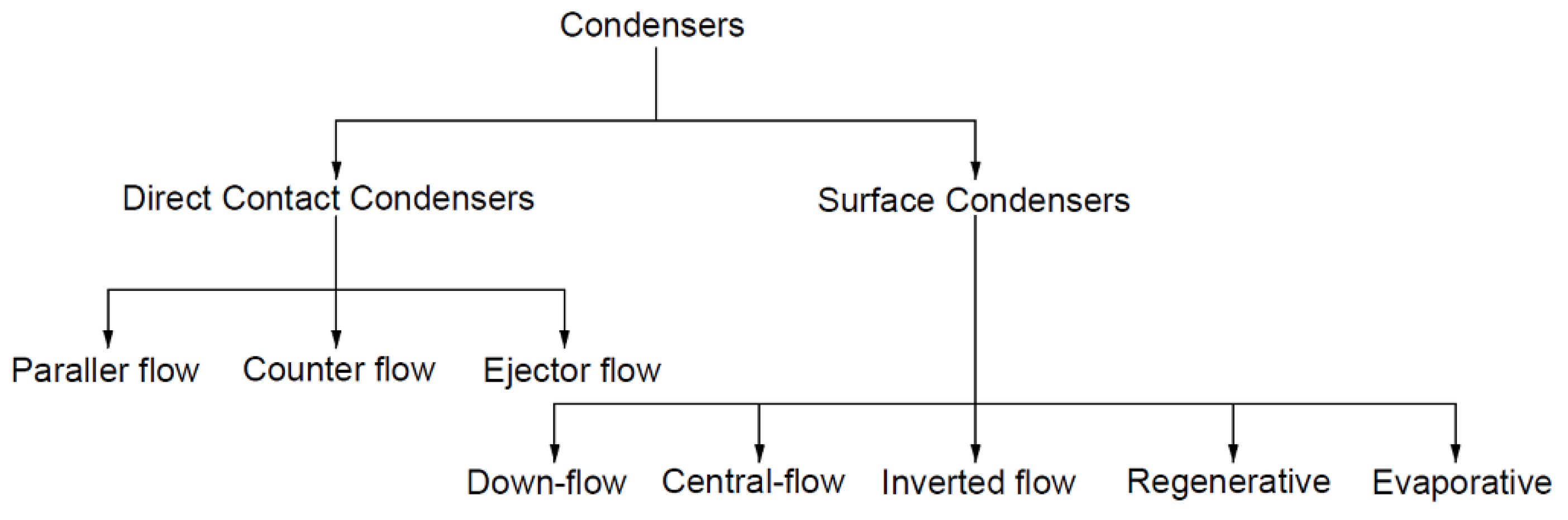
Figure 1. Classification of condensers.
In a parallel flow jet type condenser, the exhaust steam and cooling water find their entry at the top of the condenser and then flow downwards, and condensate and water are finally collected at the bottom (Figure 2).
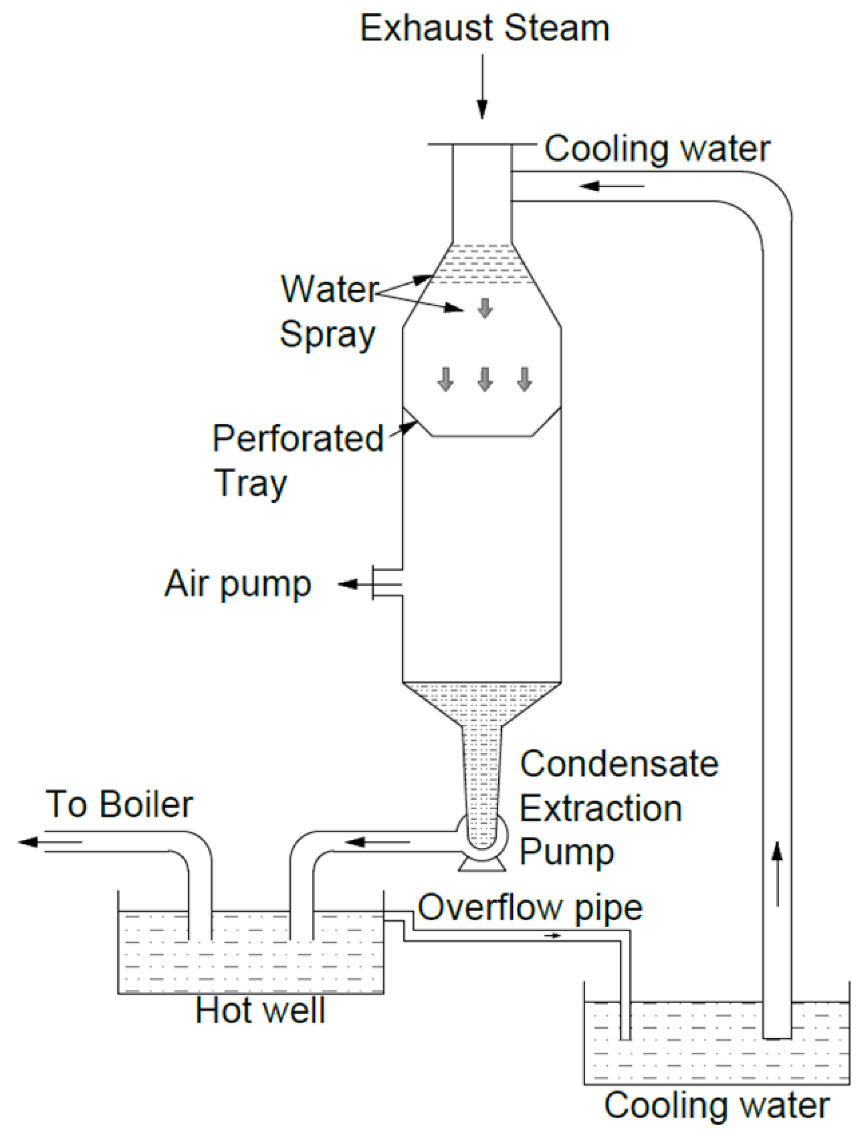
Figure 2. Parallel flow type condenser.
The steam and cooling water enter the condenser from opposite directions in a counter jet type condenser. Generally, the exhaust steam travels upward and meets the cooling water, which flows downwards. In this low-level jet-type condenser (counter jet type condenser), presented in Figure 3, the exhaust steam enters slightly lower than in a parallel flow jet-type condenser, and the cooling water is supplied from the top of the condenser chamber (Figure 3). The direction of the steam is upward, and the cooling water is downward. An air pump creates a vacuum and is placed on top of the condenser. The vacuum sucks the cooling water, and a hollow cone plate collects the falling water, which joins the second series of streams and meets the exhaust steam entering from below. The resulting condensate is delivered to the tank through a vertical pipe by the condensate pump. Another solution of counter jet type condensers is called barometric condenser and is presented in Figure 4. In this type, the shell is placed at the height of about 10.363 m above the hot well; thus, there is no need to provide an extraction pump. Provision of providing injection pump is observed, where water under pressure is unavailable.
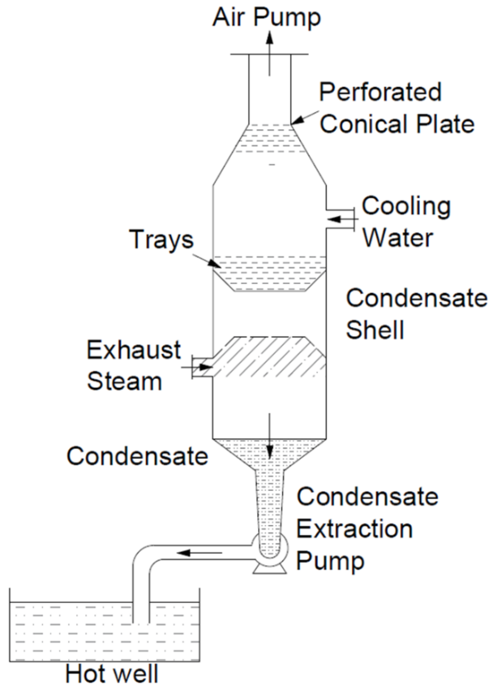
Figure 3. Low-level counter-flow jet type condenser.
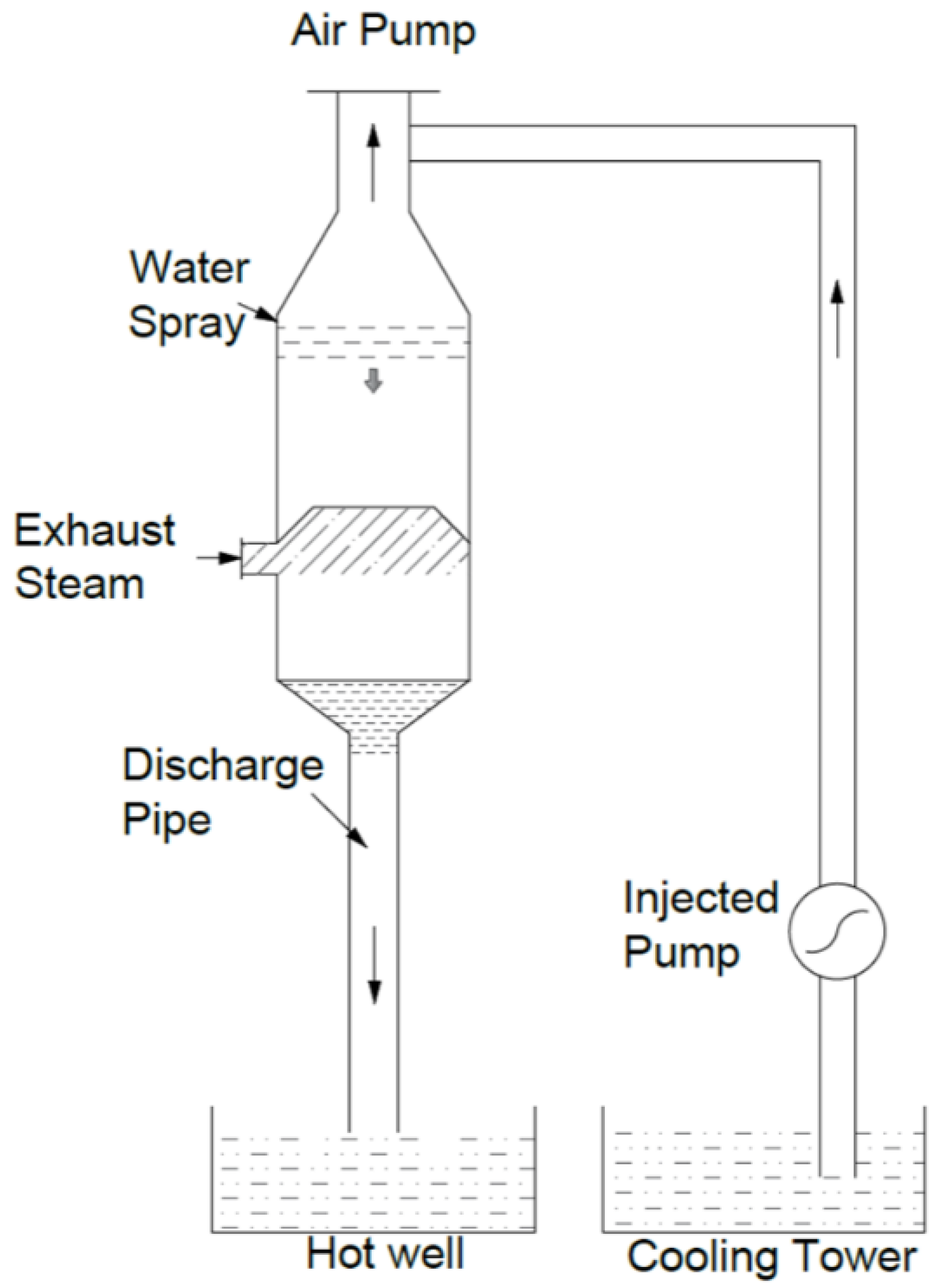
Figure 4. High-level counter-flow jet type condenser.
In Figure 4, the discharge pipe is connected to the bottom of the condenser shell. The exhaust steam enters the system in the lower part of the condenser, with the flow direction pointing upwards. Cooling water enters at the top and is collected by a punched cone plate. An air pump creates the vacuum on top of the shell. Steam and cooling water mix together and are carried through a discharge pipe to the tank. The difference between low and high-level jet condensers is that there is no pump between the tank and the discharge pipe in the high-level type.
The last type of jet condenser is an ejector flow jet type condenser (Figure 5). Here the exhaust steam and cooling water mix in hollow truncated cones. Due to this decreased pressure, exhaust steam and associated air are drawn through the truncated cones, finally leading to the diverging cone. In the diverging cone, a portion of kinetic energy is converted into pressure energy which is more than the atmospheric, so that condensate consisting of condensed steam, cooling water, and the air is discharged into the hot well. The exhaust steam inlet is provided with a non-return valve which does not allow the water from the hot well to rush back to the engine in case of cooling water supply to the condenser.
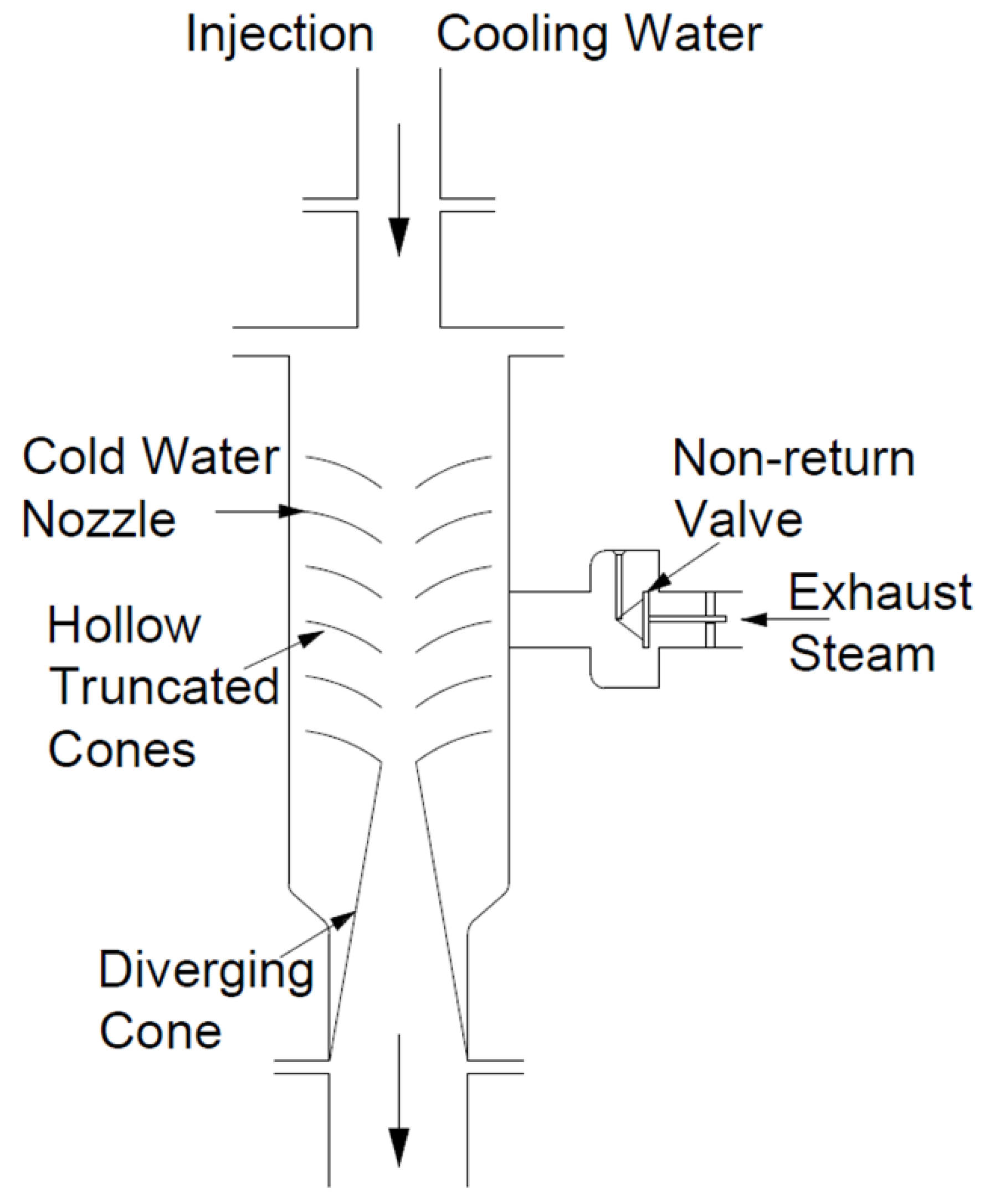
Figure 5. Ejector-flow jet type condenser.
The cooling cycle makes use of a steam ejector condenser. The steam ejector condenser is classified into two types based on the mixing method in the primary nozzle exit [7][26]. The first one is the constant pressure jet ejector (CPJE), and the other one is the constant area jet ejector (CAJE). The CPJE performs better than the CAJE due to better turbulent mixing [7][27]. In addition to having no moving parts, the steam ejector condenser benefits from lower maintenance and capital cost than the compressor.
2.2. Water and Gas Separation
After the exhaust passes through the Direct Contact Condenser (DCC) for condensation, the condensate water from the DCC consists of a proportion of non-condensable gases such as CO2, air, or other gases. The stream is passed through the separator or non-condensable gas removal system, which separates the water and the non-condensable gases. By this method, the separated CO2 can be sent to the CCU unit for further utilization, or the separated air gases can be removed from the system. Gas separation from the DCC outlet stream can be carried out in various methods. The axial flow cyclone separator is the most commonly used gas-liquid separation method widely used in industries. Kou et al. [28] simulated and experimentally proved gas-liquid separation using an axial flow cyclone separator. The experiment is conducted by passing the gas-liquid mixture stream into the cylindrical axial flow separator. A guide vane at the bottom of the cyclone separator produces centrifugal force in the fluid passing through it. Once the fluid passes into the separator, the centrifugal force created in the fluid separates the gas and liquid due to the density difference. While the liquid is collected at the bottom, the gas escapes through the top of the separator [28][29]. Ji et al. [29] experimentally proved that the efficiency of the cyclone separator could be improved by combining components to the cyclone separator. The combined cyclone separator includes components such as a steady flow element, leaf grind element, and folding plate element, which increases the efficiency of gas-liquid separation by more than 95%. Chemical looping is one of the methods of splitting the H2O and CO2 in the exhaust gas. The exhaust, which consists of H2O and CO2 undergoes a chemical reaction with the metal oxide used in chemical looping and produces different components. Farooqui et al. [30] state the process of chemical looping with cerium oxide (CeO2). The H2O and CO2 are pressurized, and the temperature is raised up to 500 °C by compression. By integrating chemical looping, oxidation occurs with CeO2, which splits H2O into Hydrogen and CO2 into carbon monoxide. The separated components from the exhaust of the chemical looping is further used for dimethyl ether (DME) production. This is considered one of the methods for CCU technology using chemical looping. Wotzka et al. [31] presented the possibility of separating CO2 and water with the application of a microporous membrane. The separation of carbon dioxide and water using an MFI zeolite membrane treated with amine is analyzed experimentally and with molecular simulation. For experimental purposes, the liquid water is heated up to 120 °C, mixed with CO2 in an evaporator, and further sent to separation. The performance of membrane separation is analyzed under different factors.
References
- Jacobs, H.R. Direct-Contact Condensation. InDirect-Contact Heat Transfer; Kreith, F., Boehm, R.F., Eds.; Springer: Berlin/Heidelberg, Germany, 1988; pp. 223–236.
- Chantasiriwan, S. Effects of cooling water flow rate and temperature on the performance of a multiple-effect evaporator. Chem. Eng.Commun. 2015, 202, 622–628.
- Zhao, X.; Fu, L.; Sun, T.; Wang, J.Y.; Wang, X.Y. The recovery of waste heat of flue gas from gas boilers. Sci. Technol. Built Environ. 2017, 23, 490–499.
- Prananto, L.A.; Juangsa, F.B.; Iqbal, R.M.; Aziz, M.; Soelaiman, T.A.F. Dry steam cycle application for excess steam utilization: Kamojang geothermal power plant case study. Renew. Energy 2018, 117, 157–165.
- Sanopoulos, D.; Karabelas, A. H2 Abatement in Geothermal Plants: Evaluation of Process Alternatives. Energy Sources 1997, 19, 63–77.
- Barabash, P.; Solomakha, A.; Sereda, V. Experimental investigation of heat and mass transfer characteristics in direct contact exchanger. Int. J. Heat Mass Transf. 2020, 162, 120359.
- Ebrahimi, M.; Keshavarz, A.; Jamali, A. Energy and exergy analyses of a micro-steam CCHP cycle for a residential building. Energy Build. 2012, 45, 202–210.
- Aidoun, Z.; Ameur, K.; Falsafioon, M.; Badache, M. Current Advances in Ejector Modeling, Experimentation and Applications for Refrigeration and Heat Pumps. Part 1: Single-Phase Ejectors. Inventions 2019, 4, 15.
- Aidoun, Z.; Ameur, K.; Falsafioon, M.; Badache, M. Current Advances in Ejector Modeling, Experimentation and Applications for Refrigeration and Heat Pumps. Part 2: Two-Phase Ejectors. Inventions 2019, 4, 16.
- Mil’man, O.O.; Anan’ev, P.A. Air-Cooled Condensing Units in Thermal Engineering (Review). Therm. Eng. 2020, 67, 872–891.
- Xu, H.; Jiang, S.; Xie, M.X.; Jia, T.; Dai, Y.J. Technical improvements and perspectives on humidification-dehumidification desalination—A review. Desalination 2022, 541, 116029.
- Narayan, G.P.; Sharqawy, M.H.; Summers, E.K.; Lienhard, J.H.; Zubair, S.M.; Antar, M.A. The potential of solar-driven humidification-dehumidification desalination for small-scale decentralized water production. Renew. Sustain. Energy Rev. 2010, 14, 1187–1201.
- Giwa, A.; Akther, N.; Al Housani, A.; Haris, S.; Hasan, S.W. Recent advances in humidification dehumidification (HDH) desalination processes: Improved designs and productivity. Renew. Sustain. Energy Rev. 2016, 57, 929–944.
- Al-Ismaili, A.M.; Jayasuriya, H. Seawater greenhouse in Oman: A sustainable technique for freshwater conservation and production. Renew. Sustain. Energy Rev. 2016, 54, 653–664.
- Kartik, S.; Balsora, H.; Sharma, M.; Saptoro, A.; Jain, R.K.; Joshi, J.B.; Sharma, A. Valorization of plastic wastes for production of fuels and value-added chemicals through pyrolysis—A review. Therm. Sci. Eng. Prog. 2022, 32, 101316.
- Qureshi, K.M.; Lup, A.N.K.; Khan, S.; Abnisa, F.; Daud, W.M.A.W. A technical review on semi-continuous and continuous pyrolysis process of biomass to bio-oil. J. Anal. Appl. Pyrolysis 2018, 131, 52–75.
- Wongwises, S.; Naphon, P. Heat-mass transfer and flow characteristics of two-phase countercurrent annular flow in a vertical pipe. Int. Commun. Heat Mass Transf. 1998, 25, 819–829.
- Han, H.; Gabriel, K. Flow physics of upward cocurrent gas-liquid annular flow in a vertical small diameter tube. Microgravity Sci. Technol. 2006, 18, 27–38.
- Ami, T.; Umekawa, H.; Ozawa, M. Dryout of counter-current two-phase flow in a vertical tube. Int. J.Multiph. Flow 2014, 67, 54–64.
- Abishek, S.; King, A.J.; Narayanaswamy, R. Computational analysis of—Two-phase flow and heat transfer in parallel and counter flow double-pipe evaporators. Int. J. Heat Mass Transf. 2017, 104, 615–626.
- Chen, W.B.; Tan, R.B.H. Theoretical analysis of two phase bubble formation in an immiscible Liquid. AIChEJ. 2003, 49, 1964–1971.
- Shilyaev, M.I.; Tolstykh, A.V. Simulation of heat and mass exchange in foam apparatus at high moisture content in vapor–gas mixture. Theor. Found. Chem. Eng. 2013, 47, 165–174.
- Lapteva, E.A.; Laptev, A.G. Models and calculations of the effectiveness of gas and liquid cooling in foam and film apparatuses. Theor. Found. Chem. Eng. 2016, 50, 430–438.
- Inaba, H.; Aoyama, S.; Haruki, N.; Horibe, A.; Nagayoshi, K. Heat and mass transfer characteristics of air bubbles and hot water by direct contact. Heat Mass Transf. 2002, 38, 449–457.
- Bezrodny, M.K.; Goliyad, N.N.; Barabash, P.A.; Kostyuk, A.P. Interphase heat-and-mass transfer in a flowing bubbling layer. Therm. Eng. 2012, 59, 479–484.
- Pianthong, K.; Seehanam, W.; Behnia, M.; Sriveerakul, T.; Aphornratana, S. Investigation and improvement of ejector refrigeration system using computational fluid dynamics technique. Energy Convers. Manag. 2007, 48, 2556–2564.
- Kim, H.D.; Setoguchi, T.; Yu, S.; Raghunathan, S. Navier-Stokes computations of the supersonic ejector-diffuser system with a second throat. J. Therm. Sci. 1999, 8, 79–83.
- Kou, J.; Li, Z. Numerical Simulation of New Axial Flow Gas-Liquid Separator. Processes 2021, 10, 64.
- Ji, L.; Zhao, Q.; Deng, H.; Zhang, L.; Deng, W. Experimental Study on a New Combined Gas–Liquid Separator. Processes 2022, 10, 1416.
- Farooqui, A.; Tomaso, F.D.; Bose, A.; Ferrero, D.; Llorca, J.; Santarelli, M. Techno-economic and exergy analysis of polygeneration plant for power and DME production with the integration of chemical looping CO2/H2O splitting. Energy Convers.Manag. 2019, 186, 200–219.
- Wotzka, A.; Jorabchi, M.N.; Wohlrab, S. Separation of H2O/CO2 mixtures by mfi membranes: Experiment and monte carlo study. Membranes 2021, 11, 439.
More
Information
Subjects:
Engineering, Mechanical
Contributors
MDPI registered users' name will be linked to their SciProfiles pages. To register with us, please refer to https://encyclopedia.pub/register
:
View Times:
7.4K
Revisions:
2 times
(View History)
Update Date:
23 Dec 2022
Table of Contents


Notice
You are not a member of the advisory board for this topic. If you want to update advisory board member profile, please contact office@encyclopedia.pub.
OK
Confirm
Only members of the Encyclopedia advisory board for this topic are allowed to note entries. Would you like to become an advisory board member of the Encyclopedia?
Yes
No
${ textCharacter }/${ maxCharacter }
Submit
Cancel
Back
Comments
${ item }
|
${ item.createdUser.fullName }
${ item.createdAt }
${ item.vote }
${ item.reply }
Delete
${ reply.createdUser.fullName }
${ reply.createdAt }
${ reply.vote }
Delete
There is no reply to this comment~
${ item.replyTextCharacter }/${ item.replyMaxCharacter }
Submit
Cancel
More
No more~
There is no comment~
${ textCharacter }/${ maxCharacter }
Submit
Cancel
${ selectedItem.replyTextCharacter }/${ selectedItem.replyMaxCharacter }
Submit
Cancel
Confirm
Are you sure to Delete?
Yes
No