Your browser does not fully support modern features. Please upgrade for a smoother experience.
Submitted Successfully!
 +1 credit
Thank you for your contribution! You can also upload a video entry or images related to this topic.
For video creation, please contact our Academic Video Service.
| Version | Summary | Created by | Modification | Content Size | Created at | Operation |
|---|---|---|---|---|---|---|
| 1 | Gang Li | -- | 2199 | 2022-12-13 15:16:24 | | | |
| 2 | Catherine Yang | -2 word(s) | 2197 | 2022-12-26 02:59:19 | | |
Video Upload Options
We provide professional Academic Video Service to translate complex research into visually appealing presentations. Would you like to try it?
Cite
If you have any further questions, please contact Encyclopedia Editorial Office.
Li, G.; Zhu, W. Gearbox Technologies for Tidal Energy Harvesting. Encyclopedia. Available online: https://encyclopedia.pub/entry/39053 (accessed on 27 July 2026).
Li G, Zhu W. Gearbox Technologies for Tidal Energy Harvesting. Encyclopedia. Available at: https://encyclopedia.pub/entry/39053. Accessed July 27, 2026.
Li, Gang, Weidong Zhu. "Gearbox Technologies for Tidal Energy Harvesting" Encyclopedia, https://encyclopedia.pub/entry/39053 (accessed July 27, 2026).
Li, G., & Zhu, W. (2022, December 21). Gearbox Technologies for Tidal Energy Harvesting. In Encyclopedia. https://encyclopedia.pub/entry/39053
Li, Gang and Weidong Zhu. "Gearbox Technologies for Tidal Energy Harvesting." Encyclopedia. Web. 21 December, 2022.
Copy Citation
Gearboxes are widely used in automobile, aerospace, energy, and process industries and are considered indispensable. Tidal flows always have very low speeds that rarely exceed 5 m/s. Lower tidal speeds result in lower turbine rotation speeds. Therefore, if conventional generators are used to produce electricity, gearboxes are necessary to achieve higher rotor speeds.
tidal current energy
tidal current energy converter
drivetrain
gearbox
1. Planetary and Multi-Stage Gearboxes
Current TCECs try to harvest more tidal energy by using PMGs and large planetary gearboxes [1]. In a 2 MW TCEC, its planetary gearbox typically has a speed ratio of around 1:150. The gearbox with that speed ratio can be designed by using three or four gear sets based on a combination of planetary and multi-stage gear sets [1][2], as shown in Figure 1. The efficiency of the drivetrain is dependent on the number of gear sets and the efficiency of each gear set. Generally, multi-stage gear sets have an efficiency of around 98%, while the efficiency of planetary gear sets even reaches 99% [3][4]. The advantages of using multi-stage gear sets are their wide availability and low costs. On the other hand, planetary gear sets are slightly more efficient and can yield higher speed ratios in compact spaces. A gear pair in a multi-stage gear set can have a speed ratio of up to 1:5, while a gear pair in a planetary gear set is built with a speed ratio of up to 1:12. Furthermore, the operational torque Tr is better distributed through more meshing gear pairs. This gives the planetary gear set a higher torque capability. Finally, bearing forces in the planetary gear set are smaller than those in multi-stage gear sets. For megawatt TCECs, costs of gearboxes are significantly reduced when using planetary gear sets due to their small sizes and masses. Planetary gear sets are preferable for megawatt TCECs. A limitation of planetary and multi-stage gearboxes is that most of their speed ratios are constant and they cannot eliminate speed fluctuations caused by variable tidal speeds and turbulence. By considering that gearboxes serve as increasers in drivetrains, they can enlarge these speed fluctuations and have large impacts on generators, which can cause generator failures.

Figure 1. Schematic of (a) a planetary gear set and (b) a multi-stage gear set.
Some commercially developed planetary gearboxes of TCECs are shown in Figure 2. Tidal Generation Ltd (TGL) developed a 500 kW tidal current turbine, i.e., Deepgen, using a 500 kW planetary gearbox and an induction generator, which was successfully deployed and connected to the grid in 2010. This 500 kW planetary gearbox had a speed ratio of 1:100.5, as shown in Figure 2a [5]. Marine Current Turbine (MCT) developed a dual horizontal-axis TCEC system i.e., SeaGen [6]. Each turbine of the SeaGen system was a 600 kW two-blade turbine that was coupled with a 650 kW planetary gearbox, which had a speed ratio of 1:110, as shown in Figure 2b. Andritz Hydro developed a 1.5 MW horizontal-axis TCEC, i.e., MeyGen [7][8]. Its nacelle included a 1.5 MW two-stage planetary gearbox, as shown in Figure 2c, and a PMG that could operate with a high harvesting efficiency over a wide tidal speed range. Orbital Marine Power Ltd (Orbital) developed a 2 MW floating TCEC, i.e., SR2-2000, using a Superposition Gear (SPG) system, which consisted of two planetary gear sets mounted on a parallel shaft [9][10], as shown in Figure 2d. The SPG system enables a variable speed ratio in the range of 1:125–1:79 and maintains a constant output speed.
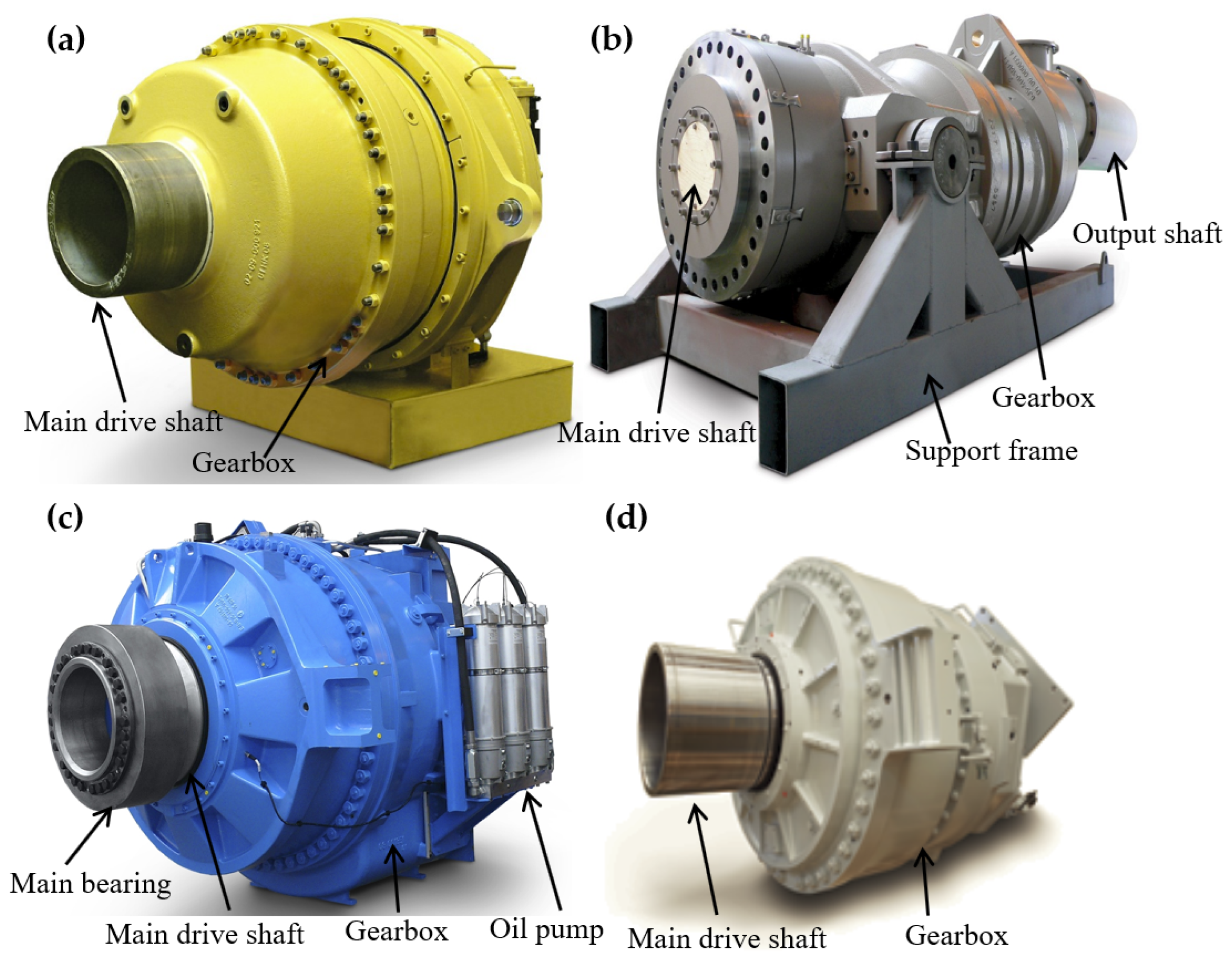
Figure 2. Some commercially developed planetary gearboxes of TCECs: (a) 500 kW planetary gearbox of a TGL turbine; (b) 650 kW planetary gearbox with a generator from a MCT’s SeaGen tidal current turbine; (c) 1.5 MW planetary gearbox from an Andritz Hydro’s MeyGen turbine; (d) 1.13 MW planetary gearbox from an Orbital Marine Power’s FloTEC SR2-2000 tidal current turbine.
2. Hydraulic Transmissions
Hydraulic transmissions were developed with hydraulic pumps and several fixed- or variable-displacement hydraulic motors [11][12]. Hydraulic pumps converted the kinetic energy of tidal turbines into the potential energy of the pressurized fluid. Hydraulic motors converted the potential energy of the pressurized fluid back into the kinetic energy of generator shafts [13]. A hydraulic transmission system of a TCEC was developed based on the digital displacement technology that converted variable turbine rotation speeds into a constant generator shaft speed [14]. A hydraulic–mechanical hybrid transmission of TCECs for maximum power point tracking (MPPT) using a planetary gear set as a power split device has also been developed [15]. In this hydraulic–mechanical hybrid transmission, the hydraulic pump displacement control was designed to vary its rotation speed to realize MPPT, and harvested tidal power could be stabilized via a hydraulic system. A hydraulic accumulator was designed for a hybrid wind–tidal turbine [16]. A hybrid turbine was developed to simultaneously capture offshore wind and tidal current energy and can store redundant energy in a hydraulic accumulator for electricity generation. Two hydraulic pumps of the hybrid turbine can be used to convert the harvested wind and tidal energy into the hydraulic energy. A closed-loop hydraulic transmission was developed for variable-speed wind turbines, which involved a hydraulic pump and a hydraulic motor [17]. While hydraulic pumps of these hydraulic transmissions can enlarge their speed ratio ranges, the efficiency of these hydraulic transmissions is only about 70–80% [14][15][18].
The above hydraulic transmissions are still in the development stage. Voith developed a commercialized hydrodynamic transmission, i.e., WinDrive, which consisted of a superimposing gearing unit and a hydraulic torque converter [19]. The superimposing gearing unit included two combined planetary gear sets. Figure 3 shows the working principle of WinDrive. The hydrodynamic torque converter in WinDrive decoupled the main drive shaft from a generator. The speed ratio and the operational torque of WinDrive can be adjusted via angles of vanes in the hydraulic torque converter. The variable speed ratio of WinDrive was in the range of 1:135–1:72. Due to this wide variable speed ratio range, a synchronous generator can be directly used for connection to the grid without power electronics.
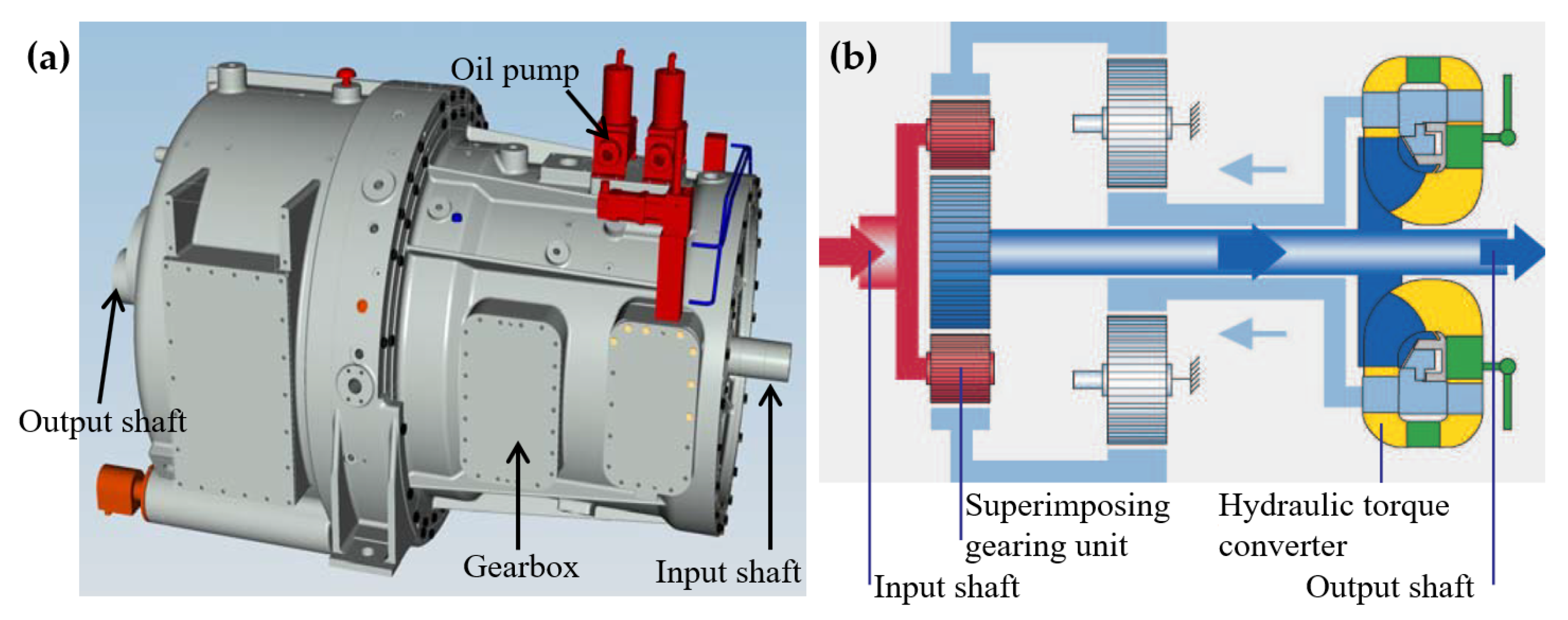
Figure 3. Hydraulic transmission WinDrive [19]: (a) a three-dimensional view and (b) the power flow in WinDrive that consisted of a superimposing gearing unit and a hydrodynamic torque converter.
3. Variable-Speed Transmissions
3.1. Continuously Variable Transmissions
Continuously variable transmissions (CVTs) can provide variable speed ratios in a wide speed ratio range to enable generators of TCECs to operate in more efficient conditions [20]. Most CVTs convert operational torques Tr of TCECs based on friction in belt/chain-pulley systems, as shown in Figure 4a. The efficiency of CVTs is low under high-torque and low-speed conditions due to sliding in belt/chain-pulley systems. Pulley-based designs commonly investigated for renewable energy applications, either belt or chain driven, are rated at kilowatt to megawatt power capacity [20][21]. Some hydrostatic transmissions [15][22][23] and flywheel systems [24] were used as power-split systems combined with traditional CVTs to improve their torque conversion capability.
Fallbrook Technologies Inc developed a new ball-actuated CVT for renewable energy applications [25][26], as shown in Figure 4b. The main components of a ball-actuated CVT are an input disk, an output disk, ball elements, and a ball angle variator. The working principle of the ball-actuated CVT is to change the speed ratio of the input drive and the output drive by varying angles of ball elements that contact input and output disks. Angles of tilts of ball elements cause changes in radii at contact points on input and output disks. Simultaneous changes in rotation radii of ball elements at these contact points cause speed ratio changes in the ball-actuated CVT. The ball-actuated CVT transfers torques from the input disc to the output disc using elastohydrodynamic lubrication. The torque capacity of the ball-actuated CVT depends on the number of ball elements. Increasing the number of ball elements enables the ball-actuated CVT to be scaled to higher torque capacities without increasing its size and significant parasitic loss.

Figure 4. Schematic of CVTs [26]: (a) a belt/chain-pully-based CVT and (b) a ball-actuated CVT.
3.2. Infinitely Variable Transmissions
An infinitely variable transmission (IVT) was designed with cam systems to achieve continuously variable speed ratios via one-way bearings [27]. An active control system of the IVT was developed there with a closed-loop control that can adjust the eccentric motions of cams to control its speed ratios. However, the instantaneous speed ratios of this IVT had a periodic speed variation of up to 29% due to cam eccentricity. An upgraded IVT was designed with crank-slider systems that could continuously adjust the speed ratio in a wide range from zero to a certain value [28][29]. A noncircular gear pair was designed there to minimize the variation in instantaneous speed ratios that were introduced by crank-slider systems.
A new IVT was developed with a noncircular gear pair and two scotch-yoke systems (SYSs) to provide continuously variable speed ratios for given constant output speeds under any variable input speeds [30][31]. A schematic of the IVT is shown in Figure 5. An input power of the IVT was transmitted through the noncircular gear pair to an input-control module (ICM) with a modulated rotation speed [31]. Two planetary gear sets (PGSs) in the ICM combined the modulated rotation speed from the noncircular gear pair and the control speed of control gears. The combined rotation speeds of PGSs were transmitted to two SYSs in a motion-conversion module (MCM) via translational motions of yokes in SYSs. SYSs converted the translational speeds of yokes into rotation speeds of the output shaft via rack–pinion sets. The IVT can be scaled up by increasing the number of SYSs and the size of PGSs. Since the IVT can convert the power via gear contact forces without sliding power loss under high-torque and low-speed conditions, the IVT fits for tidal current energy harvesting. Additionally, the range of the variable speed ratio of the IVT is larger than that of a CVT and can start from zero. Since the output-to-input speed ratio of the IVT can be zero, a TCEC with the IVT can be disconnected from the grid without power electronic control and couplings at low tidal speeds in Region 1. A large variable speed ratio range of the IVT enables high operation performance of the TCEC in its optimal speed range with the maximum harvesting efficiency. An integral time-delay feedback control with an open-loop control [32] and a closed-loop control [33][34] was designed to improve the control performance of the IVT for tidal current energy applications. Experimental investigation of the closed-loop control strategy of the IVT was conducted with variable tidal speed data [35][36]. Experimental results showed that the time-delay feedback control could reduce speed fluctuations of the output speed of the IVT.
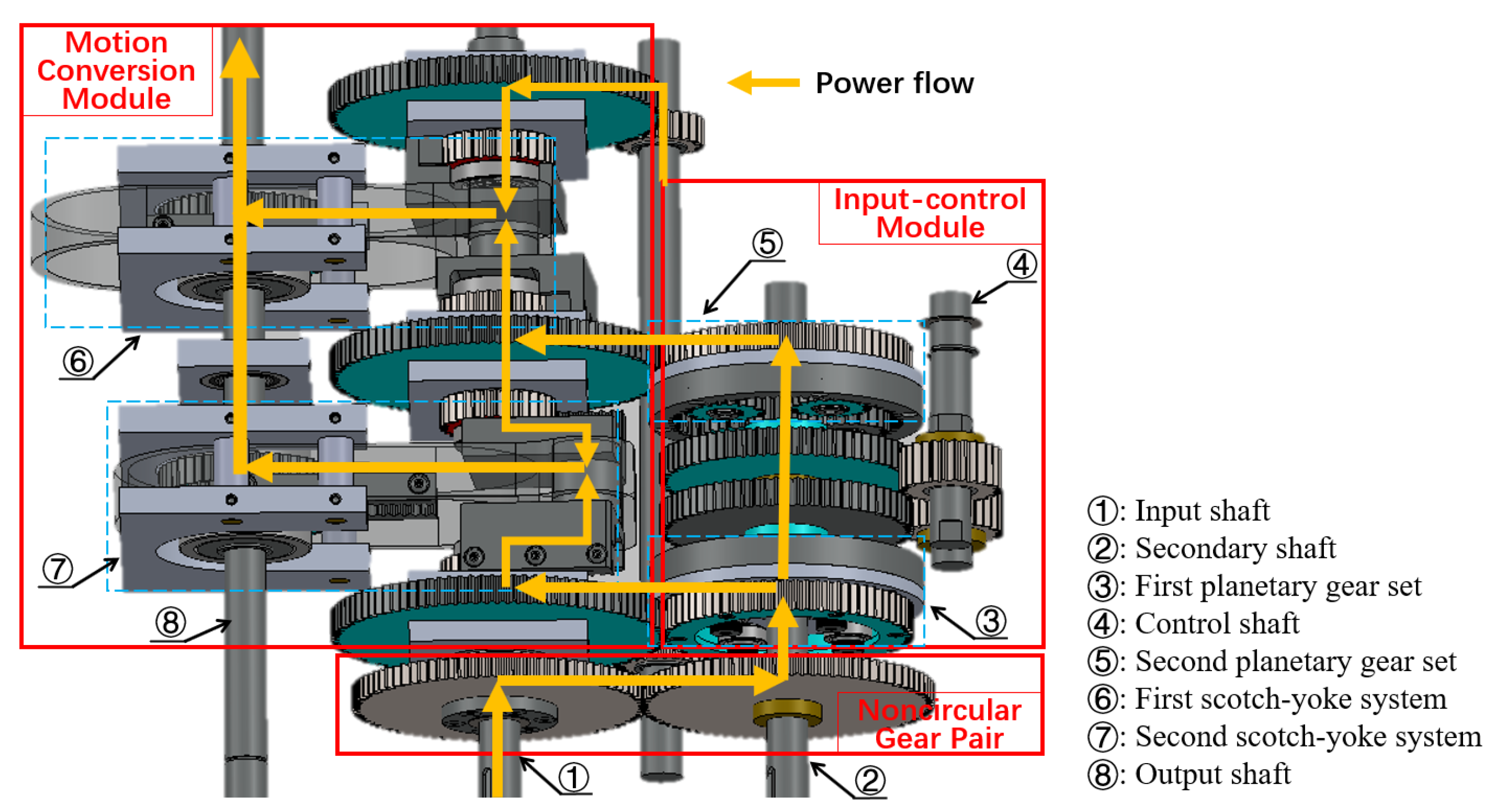
Figure 5. Schematic of the IVT [30].
4. Direct-Drive Systems
In a direct-drive system, a direct-drive generator is directly driven by the turbine hub [37][38][39]. Currently, direct-drive permanent-magnet (DDPM) synchronous generators are one of the attractive options for direct-drive systems for wind and marine energy harvesting since they have high power generation efficiency even though they are more expensive than generator systems with gearboxes [40][41][42][43]. DDPM synchronous generators were developed to improve the reliability of TCECs and reduce their O&M costs as gearboxes can be eliminated. Typically, DDPM synchronous generators can be divided into two categories: axial-flux and radial-flux DDPM synchronous generators, according to their flux directions in air gaps [44][45], as shown in Figure 6. The flux path in an axial-flux DDPM synchronous generator is predominantly axial; the flux enters and leaves the generator at the same side [46]. The flux in a radial-flux DDPM synchronous generator travels in the radial direction through its air gaps. Figure 6a shows a single-stator single-rotor axial-flux DDPM synchronous generator, which consists of a stator and a rotor. The stator can be manufactured with or without slots depending on the type of application [47]. Active conductors of the axial-flux DDPM synchronous generator are oriented along its radius direction and the magnet flux is oriented in its axial direction. Figure 6b shows a radial-flux DDPM synchronous generator in a rim-driven turbine. In this rim-driven structure, active conductors of the radial-flux DDPM synchronous generator are oriented along its axial direction and the magnetic flux is along its radial direction.
These axial-flux and radial-flux DDPM synchronous generators are associated with turbines of TCECs in pod-type and rim-driven structures, respectively, as shown in Figure 7 [48][49]. A hollow center turbine structure can be used for high-diameter radial-flux DDPM synchronous generators, as shown in Figure 7b. Generally, radial-flux DDPM synchronous generators have been the dominant force between these two DDPM synchronous generators, mainly due to the fact that these radial-flux DDPM synchronous generators have naturally evolved from induction generators [50]. However, there are many unique advantages to be gained with the use of axial-flux DDPM synchronous generators over radial-flux DDPM synchronous generators. The pod-type structure is mostly used for PMGs, which leads to compact-sized axial-flux DDPM synchronous generators with a higher power density compared to conventional radial-flux DDPM synchronous generators [51]. For tidal current energy harvesting, some direct-drive systems have been developed in both academic and industrial projects [37][52][53][54][55][56]. These studies particularly dealt with specific structure topologies of PMGs for TCECs. However, it has not been proven that the reliability of direct-drive TCECs is better than that of TCECs with gearboxes [57].
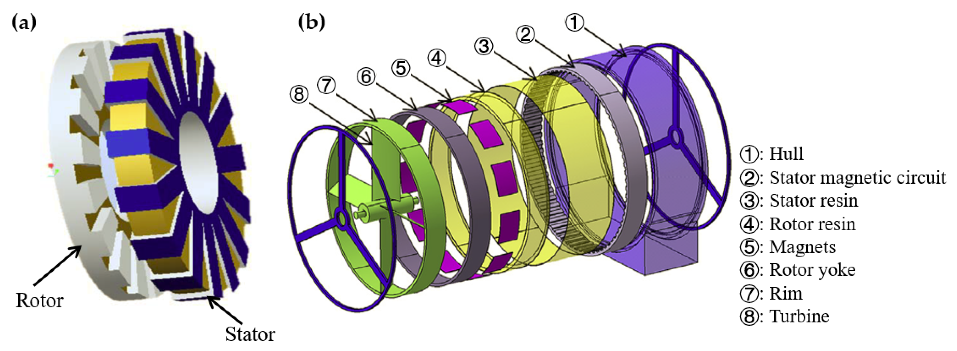

Figure 7. Two direct-drive TCEC structures: (a) the pod-type structure of a Sabella D10-1000 tidal current turbine and (b) the rim-driven structure of an OpenHydro tidal current turbine.
References
- Khare, V.; Khare, C.; Nema, S.; Baredar, P. Tidal Energy Systems: Design, Optimization and Control; Elsevier: Amsterdam, The Netherlands, 2018.
- Hau, E. Wind Turbines: Fundamentals, Technologies, Application, Economics; Springer Science & Business Media: Berlin/Heidelberg, Germany, 2013.
- Marques, P.M.; Camacho, R.; Martins, R.C.; Seabra, J.H. Efficiency of a planetary multiplier gearbox: Influence of operating conditions and gear oil formulation. Tribol. Int. 2015, 92, 272–280.
- Elmaati, Y.A.; El Bahir, L.; Faitah, K. Residual generation for the gearbox efficiency drop fault detection in the NREL 1.5 WindPact turbine. In Proceedings of the 2015 International Conference on Electrical and Information Technologies (ICEIT), Marrakech, Morocco, 25–27 March 2015; pp. 77–81.
- Warren, T. FoDTEC (Forensic Decommissioning of Tidal Energy Converters) Final Summary Report; Technical Report; Interreg North-West Europe FORESEA: Lille, France, 2012.
- Snieckus, D. Pioneering SeaGen Tidal Power Turbine Decommissioned. 2019. Available online: https://www.rechargenews.com/technology/pioneering-seagen-tidal-power-turbine-decommissioned/2-1-644606 (accessed on 24 July 2021).
- Poindexter, G. 1.5-MW AR1500 Tidal Turbine Grid-Connected, Operational at Full Power in Scotland. 2017. Available online: https://www.renewableenergyworld.com/baseload/1-5-mw-ar1500-tidal-turbine-grid-connected-operational-at-full-power-in-scotland/#gref (accessed on 3 February 2017).
- Poindexter, G. Tidal Power Technology Company Atlantis Resources Posts US$9.4 Million Loss for 2016. 2017. Available online: https://www.hydroreview.com/business-finance/tidal-power-technology-company-atlantis-resources-posts-us-9-4-million-loss-for-2016/#gref (accessed on 1 June 2017).
- McPhee, D. Scotrenewables Rebrands as It Looks to Raise 7M Investment; Technical Report; Energy Voice: Aberdeen, UK, 2018.
- Whitlock, R. SR2000 Tidal Turbine Delivered Impressive Performance throughout the Winter. 2018. Available online: https://www.renewableenergymagazine.com/ocean_energy/sr2000-tidal-turbine-delivered-impressive-performance-through-20180116 (accessed on 16 January 2018).
- Dong, X.; Wang, Z.; Shen, P.; Song, Y.; Yu, J. Novel design of speed-increasing compound coupled hydromechanical transmission on tidal current turbine for power generation. E3S Web Conf. EDP Sci. 2020, 162, 03001.
- He, X.; Xiao, G.; Hu, B.; Tan, L.; Tang, H.; He, S.; He, Z. The applications of energy regeneration and conversion technologies based on hydraulic transmission systems: A review. Energy Convers. Manag. 2020, 205, 112413.
- Liu, H.-W.; Li, W.; Lin, Y.-G.; Ma, S. Tidal current turbine based on hydraulic transmission system. J. Zhejiang Univ.-SCIENCE A 2011, 12, 511–518.
- Payne, G.; Kiprakis, A.; Ehsan, M.; Rampen, W.H.S.; Chick, J.; Wallace, A. Efficiency and dynamic performance of Digital Displacement™ hydraulic transmission in tidal current energy converters. Proc. Inst. Mech. Eng. Part A J. Power Energy 2007, 221, 207–218.
- Liu, H.; Lin, Y.; Shi, M.; Li, W.; Gu, H.; Xu, Q.; Tu, L. A novel hydraulic-mechanical hybrid transmission in tidal current turbines. Renew. Energy 2015, 81, 31–42.
- Fan, Y.; Mu, A.; Ma, T. Modeling and control of a hybrid wind-tidal turbine with hydraulic accumulator. Energy 2016, 112, 188–199.
- Laguna, A.J.; Diepeveen, N.F.; Van Wingerden, J.W. Analysis of dynamics of fluid power drive-trains for variable speed wind turbines: Parameter study. IET Renew. Power Gener. 2014, 8, 398–410.
- Qian, P.; Feng, B.; Liu, H.; Tian, X.; Si, Y.; Zhang, D. Review on configuration and control methods of tidal current turbines. Renew. Sustain. Energy Rev. 2019, 108, 125–139.
- Müller, H.; Pöller, M.; Basteck, A.; Tilscher, M.; Pfister, J. Grid compatibility of variable speed wind turbines with directly coupled synchronous generator and hydro-dynamically controlled gearbox. In Proceedings of the Sixth International Workshop on Large-Scale Integration of Wind Power and Transmission Networks for Offshore Wind Farms, Delft, The Netherlands, 26–28 October 2006; pp. 307–315.
- Giallanza, A.; Porretto, M.; Cannizzaro, L.; Marannano, G. Analysis of the maximization of wind turbine energy yield using a continuously variable transmission system. Renew. Energy 2017, 102, 481–486.
- Verdonschot, M. Modeling and Control of Wind Turbines Using a Continuously Variable Transmission. Master’s Thesis, Eindhoven University of Technology, Eindhoven, The Netherlands, 2009.
- Yin, X.X.; Lin, Y.G.; Li, W.; Liu, H.W.; Gu, Y.J. Output power control for hydro-viscous transmission based continuously variable speed wind turbine. Renew. Energy 2014, 72, 395–405.
- Shamshirband, S.; Petković, D.; Amini, A.; Anuar, N.B.; Nikolić, V.; Ćojbašić, Ž.; Kiah, M.L.M.; Gani, A. Support vector regression methodology for wind turbine reaction torque prediction with power-split hydrostatic continuous variable transmission. Energy 2014, 67, 623–630.
- Van Berkel, K.; Hofman, T.; Vroemen, B.; Steinbuch, M. Optimal control of a mechanical hybrid powertrain. IEEE Trans. Veh. Technol. 2011, 61, 485–497.
- Cotrell, J. Motion Technologies CRADA CRD-03-130: Assessing the Potential of a Mechanical Continuously Variable Transmission; Technical Report; National Renewable Energy Lab.: Golden, CO, USA, 2004.
- Alkan, D. Investigating CVT as a Transmission System Option for Wind Turbines. Master’s Thesis, KTH School of Industrial Engineering and Management, Stockholm, Sweden, 2013.
- Zhu, W.; Wang, X. Modeling and control of an infinitely variable speed converter. ASME J. Dyn. Syst. Meas. Control 2014, 136, 031015.
- Wang, X.; Zhu, W. Design, modeling, and simulation of a geared infinitely variable transmission. ASME J. Mech. Des. 2014, 136.
- Zhu, W.; Wang, X. Geared Infinitely Variable Transmission. U.S. Patent 9,222,558 B2, 12 December 2015.
- Wang, X.F.; Zhu, W.D. Design, modeling, and experimental validation of a novel infinitely variable transmission based on scotch yoke systems. ASME J. Mech. Des. 2016, 138, 015001.
- Li, G.; Zhu, W. Design and power loss evaluation of a noncircular gear pair for an infinitely variable transmission. Mech. Mach. Theory 2021, 156, 104137.
- Wang, X.F.; Zhu, W.D. Design and stability analysis of an integral time-delay feedback control combined with an open-loop control for an infinitely variable transmission system. ASME J. Dyn. Syst. Meas. Control 2018, 140, 011007.
- Li, G.; Wang, X.; Zhu, W. Theoretical and experimental investigation on an integral time-delay feedback control combined with a closed-loop control for an infinitely variable transmission system. Mech. Mach. Theory 2021, 164, 104410.
- Zhu, W.; Wang, X.; Li, G. Closed-Loop Control of an Infinitely Variable Transmission. U.S. Patent 11,268,615 B2, 8 March 2022.
- Li, G.; Zhu, W. Experimental investigation on control of an infinitely variable transmission system for tidal current energy converters. IEEE/ASME Trans. Mechatron. 2021, 26, 1960–1967.
- Li, G.; Zhu, W. Time-delay closed-loop control of an infinitely variable transmission system for tidal current energy converters. Renew. Energy 2022, 189, 1120–1132.
- Keysan, O.; McDonald, A.S.; Mueller, M. A direct drive permanent magnet generator design for a tidal current turbine (SeaGen). In Proceedings of the 2011 IEEE International Electric Machines & Drives Conference (IEMDC), Niagara Falls, ON, Canada, 5–8 May 2011; pp. 224–229.
- McMillan, D.; Ault, G.W. Techno-economic comparison of operational aspects for direct drive and gearbox-driven wind turbines. IEEE Trans. Energy Convers. 2010, 25, 191–198.
- Ousmane Samb, S.; Bernard, N.; Fouad Benkhoris, M.; Kien Bui, H. Design optimization of a direct-drive electrically excited synchronous generator for tidal wave energy. Energies 2022, 15, 3174.
- Polinder, H.; Van der Pijl, F.F.; De Vilder, G.J.; Tavner, P.J. Comparison of direct-drive and geared generator concepts for wind turbines. IEEE Trans. Energy Convers. 2006, 21, 725–733.
- Delfino, F.; Denegri, G.; Invernizzi, M.; Pampararo, F.; Procopio, R.; Rossi, M. Modeling and control of DDPM wind generators. In Proceedings of the 45th International Universities Power Engineering Conference UPEC2010, Cardiff, UK, 31August–3 September 2010; pp. 1–5.
- Li, H.; Chen, Z. Overview of different wind generator systems and their comparisons. IET Renew. Power Gener. 2008, 2, 123–138.
- Faiz, J.; Nematsaberi, A. Linear electrical generator topologies for direct-drive marine wave energy conversion-an overview. IET Renew. Power Gener. 2017, 11, 1163–1176.
- Chen, Y.; Pillay, P.; Khan, A. PM wind generator topologies. IEEE Trans. Ind. Appl. 2005, 41, 1619–1626.
- Singh, A.; Benzaquen, J.; Mirafzal, B. Current source generator–converter topology for direct-drive wind turbines. IEEE Trans. Ind. Appl. 2017, 54, 1663–1670.
- Kahourzade, S.; Mahmoudi, A.; Ping, H.W.; Uddin, M.N. A comprehensive review of axial-flux permanent-magnet machines. Can. J. Electr. Comput. Eng. 2014, 37, 19–33.
- Amin, S.; Khan, S.; Bukhari, S.S.H. A comprehensive review on axial flux machines and its applications. In Proceedings of the 2019 2nd International Conference on Computing, Mathematics and Engineering Technologies (iCoMET), Sukkur, Pakistan, 30–31 January 2019; pp. 1–7.
- Zhou, Z.; Benbouzid, M.; Charpentier, J.F.; Scuiller, F.; Tang, T. Developments in large marine current turbine technologies—A review. Renew. Sustain. Energy Rev. 2017, 71, 852–858.
- Zhou, Z.; Scuiller, F.; Charpentier, J.F.; Benbouzid, M.; Tang, T. An up-to-date review of large marine tidal current turbine technologies. In Proceedings of the 2014 International Power Electronics and Application Conference and Exposition, Shanghai, China, 1–7 November 2014; pp. 480–484.
- Chen, Y.; Fu, W.N.; Ho, S.L.; Liu, H. A quantitative comparison analysis of radial-flux, transverse-flux, and axial-flux magnetic gears. IEEE Trans. Magn. 2014, 50, 1–4.
- Djebarri, S.; Charpentier, J.F.; Scuiller, F.; Benbouzid, M. Comparison of direct-drive PM generators for tidal turbines. In Proceedings of the 2014 International Power Electronics and Application Conference and Exposition, Shanghai, China, 1–7 November 2014; pp. 474–479.
- Jin, J.; Charpentier, J.F.; Tang, T. Preliminary design of a TORUS type axial flux generator for direct-driven tidal current turbine. In Proceedings of the 2014 First International Conference on Green Energy ICGE 2014, Sfax, Tunisia, 25 March 2014; pp. 20–25.
- Harkati, N.; Moreau, L.; Zaim, M.; Charpentier, J.F. Low speed doubly salient permanent magnet generator with passive rotor for a tidal current turbine. In Proceedings of the 2013 International Conference on Renewable Energy Research and Applications (ICRERA), Madrid, Spain, 20–23 October 2013; pp. 528–533.
- Funieru, B.; Binder, A. Design of a PM direct drive synchronous generator used in a tidal stream turbine. In Proceedings of the 2013 International Conference on Clean Electrical Power (ICCEP), Venue Alghero, Italy, 11–13 June 2013; pp. 197–202.
- Chen, H.; At-Ahmed, N.; Machmoum, M.; Zam, M.E.H. Modeling and vector control of marine current energy conversion system based on doubly salient permanent magnet generator. IEEE Trans. Sustain. Energy 2015, 7, 409–418.
- Hodgins, N.; McDonald, A.; Shek, J.; Keysan, O.; Mueller, M. Current and future developments of the C-GEN lightweight direct drive generator for wave & tidal energy. In Proceedings of the European Wave and Tidal Energy Conference, Uppsala, Sweden, 7–11 September 2009; pp. 352–359.
- Touimi, K.; Benbouzid, M.; Tavner, P. Tidal stream turbines: With or without a Gearbox? Ocean Eng. 2018, 170, 74–88.
More
Information
Subjects:
Engineering, Mechanical; Engineering, Marine; Energy & Fuels
Contributors
MDPI registered users' name will be linked to their SciProfiles pages. To register with us, please refer to https://encyclopedia.pub/register
:
View Times:
3.0K
Revisions:
2 times
(View History)
Update Date:
26 Dec 2022
Table of Contents


Notice
You are not a member of the advisory board for this topic. If you want to update advisory board member profile, please contact office@encyclopedia.pub.
OK
Confirm
Only members of the Encyclopedia advisory board for this topic are allowed to note entries. Would you like to become an advisory board member of the Encyclopedia?
Yes
No
${ textCharacter }/${ maxCharacter }
Submit
Cancel
Back
Comments
${ item }
|
${ item.createdUser.fullName }
${ item.createdAt }
${ item.vote }
${ item.reply }
Delete
${ reply.createdUser.fullName }
${ reply.createdAt }
${ reply.vote }
Delete
There is no reply to this comment~
${ item.replyTextCharacter }/${ item.replyMaxCharacter }
Submit
Cancel
More
No more~
There is no comment~
${ textCharacter }/${ maxCharacter }
Submit
Cancel
${ selectedItem.replyTextCharacter }/${ selectedItem.replyMaxCharacter }
Submit
Cancel
Confirm
Are you sure to Delete?
Yes
No