Your browser does not fully support modern features. Please upgrade for a smoother experience.
Please note this is a comparison between Version 1 by Gang Li and Version 2 by Catherine Yang.
Gearboxes are widely used in automobile, aerospace, energy, and process industries and are considered indispensable. Tidal flows always have very low speeds that rarely exceed 5 m/s. Lower tidal speeds result in lower turbine rotation speeds. Therefore, if conventional generators are used to produce electricity, gearboxes are necessary to achieve higher rotor speeds.
- tidal current energy
- tidal current energy converter
- drivetrain
- gearbox
1. Planetary and Multi-Stage Gearboxes
Current TCECs try to harvest more tidal energy by using PMGs and large planetary gearboxes [1][71]. In a 2 MW TCEC, its planetary gearbox typically has a speed ratio of around 1:150. The gearbox with that speed ratio can be designed by using three or four gear sets based on a combination of planetary and multi-stage gear sets [1][2][50,71], as shown in Figure 13. The efficiency of the drivetrain is dependent on the number of gear sets and the efficiency of each gear set. Generally, multi-stage gear sets have an efficiency of around 98%, while the efficiency of planetary gear sets even reaches 99% [3][4][72,73]. The advantages of using multi-stage gear sets are their wide availability and low costs. On the other hand, planetary gear sets are slightly more efficient and can yield higher speed ratios in compact spaces. A gear pair in a multi-stage gear set can have a speed ratio of up to 1:5, while a gear pair in a planetary gear set is built with a speed ratio of up to 1:12. Furthermore, the operational torque Tr is better distributed through more meshing gear pairs. This gives the planetary gear set a higher torque capability. Finally, bearing forces in the planetary gear set are smaller than those in multi-stage gear sets. For megawatt TCECs, costs of gearboxes are significantly reduced when using planetary gear sets due to their small sizes and masses. Planetary gear sets are preferable for megawatt TCECs. A limitation of planetary and multi-stage gearboxes is that most of their speed ratios are constant and they cannot eliminate speed fluctuations caused by variable tidal speeds and turbulence. By considering that gearboxes serve as increasers in drivetrains, they can enlarge these speed fluctuations and have large impacts on generators, which can cause generator failures.
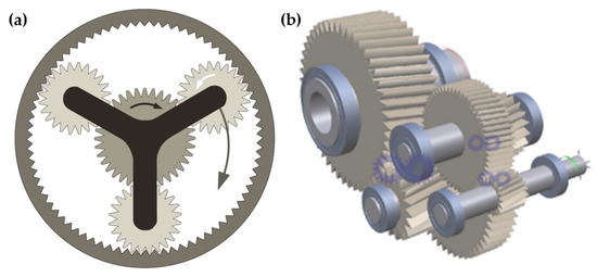
Figure 13.
Schematic of (
a
) a planetary gear set and (
b
) a multi-stage gear set.
Some commercially developed planetary gearboxes of TCECs are shown in Figure 24. Tidal Generation Ltd (TGL) developed a 500 kW tidal current turbine, i.e., Deepgen, using a 500 kW planetary gearbox and an induction generator, which was successfully deployed and connected to the grid in 2010. This 500 kW planetary gearbox had a speed ratio of 1:100.5, as shown in Figure 24a [5][74]. Marine Current Turbine (MCT) developed a dual horizontal-axis TCEC system i.e., SeaGen [6][75]. Each turbine of the SeaGen system was a 600 kW two-blade turbine that was coupled with a 650 kW planetary gearbox, which had a speed ratio of 1:110, as shown in Figure 24b. Andritz Hydro developed a 1.5 MW horizontal-axis TCEC, i.e., MeyGen [7][8][76,77]. Its nacelle included a 1.5 MW two-stage planetary gearbox, as shown in Figure 24c, and a PMG that could operate with a high harvesting efficiency over a wide tidal speed range. Orbital Marine Power Ltd (Orbital) developed a 2 MW floating TCEC, i.e., SR2-2000, using a Superposition Gear (SPG) system, which consisted of two planetary gear sets mounted on a parallel shaft [9][10][78,79], as shown in Figure 24d. The SPG system enables a variable speed ratio in the range of 1:125–1:79 and maintains a constant output speed.
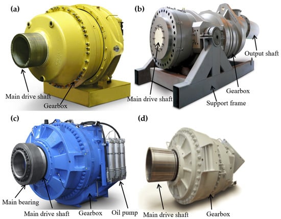
Figure 24. Some commercially developed planetary gearboxes of TCECs: (a) 500 kW planetary gearbox of a TGL turbine; (b) 650 kW planetary gearbox with a generator from a MCT’s SeaGen tidal current turbine; (c) 1.5 MW planetary gearbox from an Andritz Hydro’s MeyGen turbine; (d) 1.13 MW planetary gearbox from an Orbital Marine Power’s FloTEC SR2-2000 tidal current turbine.
2. Hydraulic Transmissions
Hydraulic transmissions were developed with hydraulic pumps and several fixed- or variable-displacement hydraulic motors [11][12][80,81]. Hydraulic pumps converted the kinetic energy of tidal turbines into the potential energy of the pressurized fluid. Hydraulic motors converted the potential energy of the pressurized fluid back into the kinetic energy of generator shafts [13][69]. A hydraulic transmission system of a TCEC was developed based on the digital displacement technology that converted variable turbine rotation speeds into a constant generator shaft speed [14][68]. A hydraulic–mechanical hybrid transmission of TCECs for maximum power point tracking (MPPT) using a planetary gear set as a power split device has also been developed [15][82]. In this hydraulic–mechanical hybrid transmission, the hydraulic pump displacement control was designed to vary its rotation speed to realize MPPT, and harvested tidal power could be stabilized via a hydraulic system. A hydraulic accumulator was designed for a hybrid wind–tidal turbine [16][83]. A hybrid turbine was developed to simultaneously capture offshore wind and tidal current energy and can store redundant energy in a hydraulic accumulator for electricity generation. Two hydraulic pumps of the hybrid turbine can be used to convert the harvested wind and tidal energy into the hydraulic energy. A closed-loop hydraulic transmission was developed for variable-speed wind turbines, which involved a hydraulic pump and a hydraulic motor [17][84]. While hydraulic pumps of these hydraulic transmissions can enlarge their speed ratio ranges, the efficiency of these hydraulic transmissions is only about 70–80% [14][15][18][68,82,85].
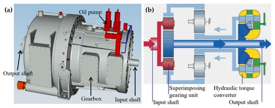
The above hydraulic transmissions are still in the development stage. Voith developed a commercialized hydrodynamic transmission, i.e., WinDrive, which consisted of a superimposing gearing unit and a hydraulic torque converter [19][86]. The superimposing gearing unit included two combined planetary gear sets. Figure 35 shows the working principle of WinDrive. The hydrodynamic torque converter in WinDrive decoupled the main drive shaft from a generator. The speed ratio and the operational torque of WinDrive can be adjusted via angles of vanes in the hydraulic torque converter. The variable speed ratio of WinDrive was in the range of 1:135–1:72. Due to this wide variable speed ratio range, a synchronous generator can be directly used for connection to the grid without power electronics.
3. Variable-Speed Transmissions
3.1. Continuously Variable Transmissions
Continuously variable transmissions (CVTs) can provide variable speed ratios in a wide speed ratio range to enable generators of TCECs to operate in more efficient conditions [20][87]. Most CVTs convert operational torques Tr of TCECs based on friction in belt/chain-pulley systems, as shown in Figure 46a. The efficiency of CVTs is low under high-torque and low-speed conditions due to sliding in belt/chain-pulley systems. Pulley-based designs commonly investigated for renewable energy applications, either belt or chain driven, are rated at kilowatt to megawatt power capacity [20][21][87,88]. Some hydrostatic transmissions [15][22][23][82,89,90] and flywheel systems [24][91] were used as power-split systems combined with traditional CVTs to improve their torque conversion capability.
Fallbrook Technologies Inc developed a new ball-actuated CVT for renewable energy applications [25][26][92,93], as shown in Figure 46b. The main components of a ball-actuated CVT are an input disk, an output disk, ball elements, and a ball angle variator. The working principle of the ball-actuated CVT is to change the speed ratio of the input drive and the output drive by varying angles of ball elements that contact input and output disks. Angles of tilts of ball elements cause changes in radii at contact points on input and output disks. Simultaneous changes in rotation radii of ball elements at these contact points cause speed ratio changes in the ball-actuated CVT. The ball-actuated CVT transfers torques from the input disc to the output disc using elastohydrodynamic lubrication. The torque capacity of the ball-actuated CVT depends on the number of ball elements. Increasing the number of ball elements enables the ball-actuated CVT to be scaled to higher torque capacities without increasing its size and significant parasitic loss.
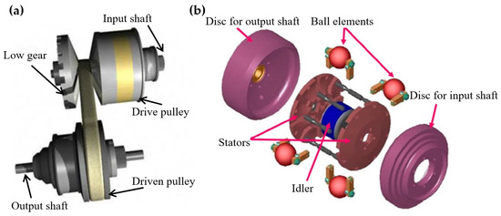
a
) a belt/chain-pully-based CVT and (
b
) a ball-actuated CVT.
3.2. Infinitely Variable Transmissions
An infinitely variable transmission (IVT) was designed with cam systems to achieve continuously variable speed ratios via one-way bearings [27][94]. An active control system of the IVT was developed there with a closed-loop control that can adjust the eccentric motions of cams to control its speed ratios. However, the instantaneous speed ratios of this IVT had a periodic speed variation of up to 29% due to cam eccentricity. An upgraded IVT was designed with crank-slider systems that could continuously adjust the speed ratio in a wide range from zero to a certain value [28][29][95,96]. A noncircular gear pair was designed there to minimize the variation in instantaneous speed ratios that were introduced by crank-slider systems.
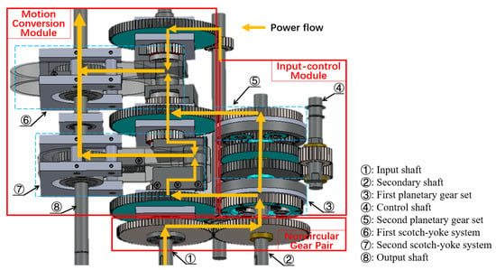
A new IVT was developed with a noncircular gear pair and two scotch-yoke systems (SYSs) to provide continuously variable speed ratios for given constant output speeds under any variable input speeds [30][31][97,98]. A schematic of the IVT is shown in Figure 57. An input power of the IVT was transmitted through the noncircular gear pair to an input-control module (ICM) with a modulated rotation speed [31][98]. Two planetary gear sets (PGSs) in the ICM combined the modulated rotation speed from the noncircular gear pair and the control speed of control gears. The combined rotation speeds of PGSs were transmitted to two SYSs in a motion-conversion module (MCM) via translational motions of yokes in SYSs. SYSs converted the translational speeds of yokes into rotation speeds of the output shaft via rack–pinion sets. The IVT can be scaled up by increasing the number of SYSs and the size of PGSs. Since the IVT can convert the power via gear contact forces without sliding power loss under high-torque and low-speed conditions, the IVT fits for tidal current energy harvesting. Additionally, the range of the variable speed ratio of the IVT is larger than that of a CVT and can start from zero. Since the output-to-input speed ratio of the IVT can be zero, a TCEC with the IVT can be disconnected from the grid without power electronic control and couplings at low tidal speeds in Region 1 in Figure 2. A large variable speed ratio range of the IVT enables high operation performance of the TCEC in its optimal speed range with the maximum harvesting efficiency. An integral time-delay feedback control with an open-loop control [32][99] and a closed-loop control [33][34][100,101] was designed to improve the control performance of the IVT for tidal current energy applications. Experimental investigation of the closed-loop control strategy of the IVT was conducted with variable tidal speed data [35][36][102,103]. Experimental results showed that the time-delay feedback control could reduce speed fluctuations of the output speed of the IVT.
4. Direct-Drive Systems
In a direct-drive system, a direct-drive generator is directly driven by the turbine hub [37][38][39][104,105,106]. Currently, direct-drive permanent-magnet (DDPM) synchronous generators are one of the attractive options for direct-drive systems for wind and marine energy harvesting since they have high power generation efficiency even though they are more expensive than generator systems with gearboxes [40][41][42][43][17,107,108,109]. DDPM synchronous generators were developed to improve the reliability of TCECs and reduce their O&M costs as gearboxes can be eliminated. Typically, DDPM synchronous generators can be divided into two categories: axial-flux and radial-flux DDPM synchronous generators, according to their flux directions in air gaps [44][45][110,111], as shown in Figure 68. The flux path in an axial-flux DDPM synchronous generator is predominantly axial; the flux enters and leaves the generator at the same side [46][112]. The flux in a radial-flux DDPM synchronous generator travels in the radial direction through its air gaps. Figure 68a shows a single-stator single-rotor axial-flux DDPM synchronous generator, which consists of a stator and a rotor. The stator can be manufactured with or without slots depending on the type of application [47][113]. Active conductors of the axial-flux DDPM synchronous generator are oriented along its radius direction and the magnet flux is oriented in its axial direction. Figure 68b shows a radial-flux DDPM synchronous generator in a rim-driven turbine. In this rim-driven structure, active conductors of the radial-flux DDPM synchronous generator are oriented along its axial direction and the magnetic flux is along its radial direction.
These axial-flux and radial-flux DDPM synchronous generators are associated with turbines of TCECs in pod-type and rim-driven structures, respectively, as shown in Figure 79 [48][49][114,115]. A hollow center turbine structure can be used for high-diameter radial-flux DDPM synchronous generators, as shown in Figure 79b. Generally, radial-flux DDPM synchronous generators have been the dominant force between these two DDPM synchronous generators, mainly due to the fact that these radial-flux DDPM synchronous generators have naturally evolved from induction generators [50][116]. However, there are many unique advantages to be gained with the use of axial-flux DDPM synchronous generators over radial-flux DDPM synchronous generators. The pod-type structure is mostly used for PMGs, which leads to compact-sized axial-flux DDPM synchronous generators with a higher power density compared to conventional radial-flux DDPM synchronous generators [51][117]. For tidal current energy harvesting, some direct-drive systems have been developed in both academic and industrial projects [37][52][53][54][55][56][104,118,119,120,121,122]. These studies particularly dealt with specific structure topologies of PMGs for TCECs. However, it has not been proven that the reliability of direct-drive TCECs is better than that of TCECs with gearboxes [57][21].
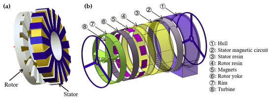
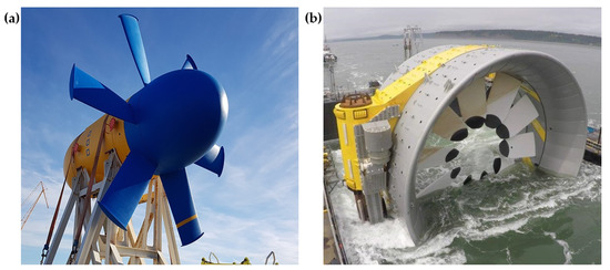
Figure 79. Two direct-drive TCEC structures: (a) the pod-type structure of a Sabella D10-1000 tidal current turbine and (b) the rim-driven structure of an OpenHydro tidal current turbine.