Your browser does not fully support modern features. Please upgrade for a smoother experience.
Submitted Successfully!
 +1 credit
Thank you for your contribution! You can also upload a video entry or images related to this topic.
For video creation, please contact our Academic Video Service.
| Version | Summary | Created by | Modification | Content Size | Created at | Operation |
|---|---|---|---|---|---|---|
| 1 | Jiawei Dong | -- | 2620 | 2022-12-07 01:43:05 | | | |
| 2 | Jessie Wu | + 89 word(s) | 2709 | 2022-12-07 07:20:27 | | | | |
| 3 | Jessie Wu | Meta information modification | 2709 | 2022-12-07 07:30:10 | | |
Video Upload Options
We provide professional Academic Video Service to translate complex research into visually appealing presentations. Would you like to try it?
Cite
If you have any further questions, please contact Encyclopedia Editorial Office.
Dong, J.; Gong, C.; Bao, J.; Zhu, L.; Hou, Y.; Wang, Z. Key Technologies for Multi-Parallel Inverter Microgrid Systems. Encyclopedia. Available online: https://encyclopedia.pub/entry/38150 (accessed on 25 July 2026).
Dong J, Gong C, Bao J, Zhu L, Hou Y, Wang Z. Key Technologies for Multi-Parallel Inverter Microgrid Systems. Encyclopedia. Available at: https://encyclopedia.pub/entry/38150. Accessed July 25, 2026.
Dong, Jiawei, Chunyang Gong, Jun Bao, Lihua Zhu, Yuanjun Hou, Zhixin Wang. "Key Technologies for Multi-Parallel Inverter Microgrid Systems" Encyclopedia, https://encyclopedia.pub/entry/38150 (accessed July 25, 2026).
Dong, J., Gong, C., Bao, J., Zhu, L., Hou, Y., & Wang, Z. (2022, December 07). Key Technologies for Multi-Parallel Inverter Microgrid Systems. In Encyclopedia. https://encyclopedia.pub/entry/38150
Dong, Jiawei, et al. "Key Technologies for Multi-Parallel Inverter Microgrid Systems." Encyclopedia. Web. 07 December, 2022.
Copy Citation
As an important form of distributed renewable energy utilization and consumption, the multi-parallel inverter microgrid system works in both an isolated and grid-connected operation mode. Secondary-frequency and voltage-regulation control are very important in solving problems that appears in these systems, such as the distributed secondary-frequency regulation real-time scheme, voltage and reactive power balancing, and the secondary-frequency regulation control under the disturbances and unbalanced conditions of a microgrid system.
multi-parallel inverter microgrid
voltage
virtual impedance technique
1. Introduction
A number of general analyses and solution techniques have been developed for the current problem of secondary voltage frequency regulation in multi-parallel inverter microgrids. In this section, some of these key technologies are introduced and analyzed in terms of their implementation methods and principles. Development trends of the methods and technologies are also analyzed.
2. Virtual Impedance Technique
Virtual impedance is a classical method used to improve the stability and reactive power-balancing accuracy of multiple parallel inverter microgrid systems [1]. A schematic diagram of the virtual impedance method is shown in Figure 1.
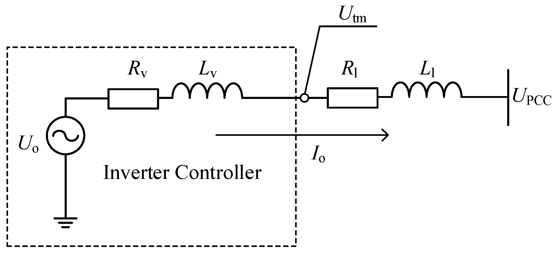
Figure 1. Schematic diagram of the virtual impedance technique.
Rv and Lv are the resistive and inductive parts of the inverter virtual impedance. Utm is the output port voltage, and Io is the inverter output current. The principle of the virtual impedance method is that the output port voltage of the inverter is changed to Utm by virtual impedance loop calculations, as if an equivalent impedance of Rv and Lv is connected in series between the inverter output port and the original output port behind the droop-control loop.
The dq-axis virtual impedance expressions are as follows:
Since the inverter control inner loop is the decoupled dq-axis PI controller, Equation (1) is commonly used for the implementation of the virtual impedance method. Thus, based on the inner current-voltage control loop illustrated, the virtual impedance control technique can be achieved by changing the reference inputs of the voltage loop from the original uc,d* and 0 to utm,dq.
The key problem with the implementation of Equation (1) is that the differential signal for the output current in it is difficult to realize. Differential calculations will lead to a significant amplification of the signal and numerical noise and should generally be avoided in inverter control loops. There are two main ways to handle the differential calculation issue. One solution is to approximate the differential link as a high-pass filter. Then, the control method in Equation (1) becomes:
The virtual impedance method is defined as transient virtual impedance in [2]. The other solution for differential calculations ignores the dq-axis current differentiation, and the virtual impedance form becomes:
A significant effect of virtual impedance control is that it can improve the accuracy of droop inverter reactive power distribution. When the line impedance of the system is proportional to the droop coefficient, that becomes:
Ignoring the voltage drop due to the reactive droop loop, the Q-U droop relationship will be restored. Generally, it is difficult to achieve the condition that the line impedance is proportional to the inverter droop coefficient. However, with the virtual impedance control technique, the relationship in Equation (4) can be restored with the virtual impedance technique. In addition, the resistive part of the virtual impedance can enhance the small-signal stability of the system [3]. There has been a considerable amount of research on virtual impedance methods and their applications. Some of these typical studies and their corresponding abstracts are reviewed in Table 1 [3][4][5][6][7][8][9][10][11][12][13][14][15][16][17][18][19][20][21][22][23].
Table 1. Review list of research on virtual impedance technique.
| Research Category | Literature | Abstract | Cost | Complexity | Effects |
|---|---|---|---|---|---|
| Method Proposed | [4][6] | Adaptive virtual impedance method for reactive power sharing based on transient virtual impedance. | Medium | Low | Power sharing |
| [8] | Particle swarm optimization based on virtual impedance design for oscillation damping. | High | Medium | Stability | |
| [11] | Virtual impedance method with dq current droop and additional compensator. | Medium | Low | Power sharing and stability | |
| [15] | Proposes a distributed adaptive virtual impedance method for stability enhancement. CAN bus communication is implemented. | High | High | Stability | |
| [17] | Successive approximation-based virtual impedance method. The value of Lv and Rv is time dynamic. | Medium | Low | Stability | |
| [19] | Adaptive virtual impedance method using consensus algorithm. | High | High | Power sharing | |
| [22] | DQ frame asymmetrical virtual impedance method. | Medium | Medium | Harmonic wave sharing | |
| [23] | Online optimization of virtual impedance scheme. | High | Medium | Power sharing | |
| Novel Application |
[5] | Uses source-side virtual impedance method for cascaded system stability enhancement. | Medium | High | Stability |
| [9] | Uses virtual impedance method for capacitive coupling inverters. | Low | Low | Stability on special situation | |
| [10] | Uses virtual impedance for active and reactive power decoupling. | Medium | High | Power sharing | |
| [18] | Multi-frequency band virtual impedance for better current quality. | High | High | Harmonic wave sharing | |
| [20] | Virtual impedance method for accurate harmonic power sharing. | High | High | Harmonic power sharing | |
| Analysis | [3] | Virtual impedance technique stability and function of circling current suppression. | \ | \ | \ |
| [7][16] | Parameter design and analysis of virtual impedance method for week grids. | \ | \ | \ | |
| [12] | Critical clearing time analysis for inverter-based power system under the impact of virtual impedance. | \ | \ | \ | |
| [13][21] | Virtual impedance method and the harmonic stability and unbalanced operation condition analysis. | \ | \ | \ | |
| [14] | Rate of change of frequency analysis for inverters with virtual impedance control scheme. | \ | \ | \ |
3. Consensus Algorithm and Event-Triggered Mechanism
The consensus algorithm is derived from graph theory. Consider a fully connected undirected graph Ξ containing M nodes inside. G is the set of all edges formed in the graph Ξ. Yij denotes the edges connecting node i and node j.
A is defined as the M × M adjacency matrix with the elements aij defined as follows:
Then, define D as the connectivity matrix whose elements are defined as follows:
Finally, define L as the Laplace matrix, and it becomes L = D − A. The matrix L is a symmetric matrix that has 0 eigenvalues, and its corresponding eigenvector is an all-one vector. Furthermore, according to Green’s disc theorem [24], it is known that the matrix L is a semi-positive definite matrix, which becomes the reason that the system with the consensus algorithm is stable.
The widely adopted leader–follower type of consensus algorithm is constituted as follows:
In Equation (7), xi is the state variable, and ui is the control input. bi is the pin coefficient. bi = 1 if the i-th node is the leader node, and bi = 0 otherwise. It can be proved [24] that the dynamic of (7) eventually converges to the reference value xref for all states xi. If the state variables in (7) are the frequency or voltage variables of a multiple parallel inverter system, the frequency and voltage of the inverters in the system will be regulated to the target value.
Recently, the consensus algorithm has been widely applied to solve the secondary-frequency and voltage-regulation problem in microgrids. However, the consensus algorithm will bring immense communication pressure to the inverter. In order to reduce the communication pressure caused by the consensus algorithm, the consensus algorithm with an event-triggering mechanism improvement is gaining more and more attention [25].
The event-triggered mechanism is similar to the idea of variable structure control [26]. The system control state updates and broadcasts its state when the system reaches a certain threshold away from the stable equilibrium point. The controller remains silent when the system is within the state threshold or the state reaches the convergence phase plane, at which point the system will spontaneously converge to the stable state even if the control state is not updated. Figure 2 shows the regulation pattern of the system with the event-triggered mechanism.
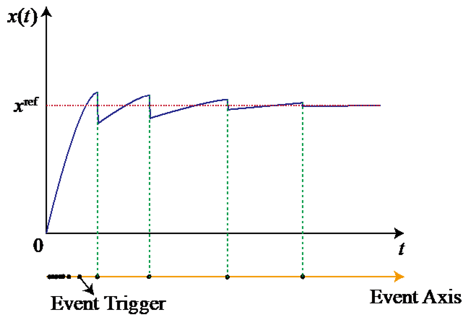
Figure 2. Regulation pattern with event-triggered mechanism.
Research on the application of event-triggered mechanisms to improve the consensus algorithm in order to optimize the frequency and voltage regulation process of multi-parallel inverter microgrids is presented in [27][28][29][30][31][32][33]. To summarize the existing designs and applications of event-triggered-based consensus algorithms, the following highlights can be mentioned regarding the design of event-triggered mechanisms.
3.1. Event-Trigger Function
The term “event” in the event-trigger mechanism refers to the event that the event function fj is greater than 0. This means that when the event-trigger function satisfies fj(t) ≥ 0, the inverters broadcast their latest output signal to the connected inverters connected on the communication network. Further, when the event-trigger function satisfies fj(t) < 0, the individual inverters remain silent, while the consensus algorithm of each inverter uses the last signal sent by the inverter communicating with it. There is a certain pattern to the design of event-trigger functions for event-triggered mechanisms, which are often in the following form:
fj(t)=ej(t)2−M(θ)zj(t)2
M(θ) is a specific function consisting of various types of coefficients related to communication or network structure parameters. ej(t) is the error function consisting of the actual value of the state variable and the consensus state variable, and zj(t) is the consensus algorithm function. For example, the event-trigger function in [27][31] are both in this form.
3.2. Zeno Phenomenon
The Zeno phenomenon refers to infinite triggering times in a short period of time [30]. No Zeno phenomenon is an important criterion for the design of event-triggered mechanisms. In general, the method used to prove that no Zeno phenomenon will occur is to show that there is a lower bound for the event-trigger time from the designed method.
3.3. Chattering
Numerical chattering can lead to frequent meaningless event triggers after the consensus algorithm has reached a steady state. Therefore, to further reduce the event-trigger frequency, the absolute or squared value of the error function ej(t) or the consensus algorithm function zj(t) can be used as an indicator to set the corresponding threshold for an anti-chattering design. However, the anti-chattering threshold should not be set too large, or it will affect the stability of the event-triggering consensus algorithm.
3.4. Consensus Signal Selection
In [27][28][29][30][31][32][33], the event-triggered consensus algorithm is adopted to design the secondary-frequency and voltage-regulation method, but the consensus signals are selected as the frequency and voltage signals themselves. According to the previous discussion of droop-based control, an important requirement in the design of the secondary-frequency and voltage regulation link based on droop control is that the secondary-frequency and voltage-regulation component of each inverter should be of the same value; otherwise, the droop characteristics will not be maintained. Therefore, in order for the droop characteristics to remain unchanged, the existing event-triggered consensus algorithms for secondary-voltage and frequency regulation adopt additional components to maintain the invariance of the droop relationship among inverters. For example, in [27][30][31], the power differential signal is introduced to compensate for the original consensus algorithm to maintain the droop relationship. In [32], an additional active power droop consensus component uPi is added to the consensus algorithm, and the whole method becomes complicated.
At present, the theory on and analysis of consensus algorithms with event-triggered mechanisms are not yet mature. The impact of the event-triggered mechanism on the small signal and transient stability of microgrid systems has not yet been fully studied.
4. Active Disturbance Rejection Control and Robust Control Method
As mentioned before, non-ideal operating conditions such as disturbances, harmonics, and imbalances are common in the operational control of multi-parallel microgrids. Therefore, control methods for frequency and voltage-regulation control under various types of disturbances and uncertainties are widely used. Among them, active disturbance rejection control (ADRC) and robust control are effective control methods for various types of disturbances and uncertainties [34].
4.1. Active Disturbance Rejection Control
ADRC is fundamentally different from robust control. ADRC emphasizes the observation of and compensation for these perturbations, and the control design procedure concentrates on the design of the perturbation observer. Robust control emphasizes the minimization of the effect of model uncertainty on the stability of the system by designing a stabilizing controller. Therefore, the design procedure concentrates on optimizing a specific robust stability criterion. In addition, the source of perturbation that is the focus of concentration by ADRC is generally external perturbation, whereas the robust control is generally targeted at model uncertainty.
The key design procedure is to design the extended state observer (ESO). (8) is known as the extended state observer (ESO). β1 and β2 are known as the observer gains.
The advantage of the ADRC control method is its ability to effectively suppress external disturbances, enabling the system to recover to the steady-state equilibrium more quickly after being disturbed. The ADRC control method has been applied in some research to design control methods for microgrid multi-parallel inverter systems with enhanced system immunity [35][36]. Ref. [35] used the ADRC control method to enhance the dynamic immunity of a frequency/voltage secondary regulation scheme based on a consistency algorithm. In [36], the ADRC method is used to enhance the dynamic performance of microgrid inverters.
4.2. Robust Control
The key to design a robust controller is to model the uncertainty of the system. System uncertainty can be divided into additive uncertainty and multiplicative uncertainty. Define z as the uncertainty model output and w as the uncertainty model input. According to the transformation between the state space and the transfer function, the matrix of the transfer function from w to z can be obtained as follows:
The H∞ control optimality problem can then be formulated as finding the control gain matrix K such that the H∞ norm of the transfer function Hzw(s) is minimized:
Furthermore, the H∞ control suboptimal problem is formulated as finding a control gain matrix K that satisfies the condition that the H∞ norm of Hzw(s) is smaller than the given constant γ:
The basic principle of H∞ control in robust control is presented above. A detailed frequency domain H∞ controller design flow is given in [37] for a typical photovoltaic DCDC converter. Summarizing the design in [37], the design of the frequency domain H∞ controller is concluded in the following flow.
(a) Transform the uncertainty terms in the control model into additive uncertainty form or multiplicative uncertainty form.
(b) Extract and separate the uncertainty terms by linear fractional transformation (LFT). Then, select the suitable weight function W and integrate it into the model G, resulting in a nominal model/uncertainty term/control matrix corresponding to the G-Δ-K form.
(c) The H∞ optimal or sub-optimal problem is solved by μ synthesis algorithm to obtain the required control gain matrix K.
There have been some studies and applications of H∞ control for the problem of the secondary regulation of frequency and voltage in a non-ideal microgrid [38][39][40][41][42]. In [38], the full flow of the design and stability analysis of the H∞ controller for grid-connected inverters is presented. The H∞ problem is solved by the μ synthesis algorithm. In [39], an inner-loop sliding-mode control and an outer-loop hybrid H2/H∞ control was adopted to design a grid-connected inverter with strong robustness, and the linear matrix inequality (LMI) algorithm was used to solve the H∞ problem. In [40], an H∞ controller is applied to a frequency quadratic regulation control loop. The H∞ problem is solved by the μ synthesis algorithm. In [41], the H∞ controller was used to design the control inner loop of a microgrid inverter for islanded operation, and the LMI algorithm was used to solve the H∞ problem. In [42], H∞ controllers are designed for improving the small-signal stability of microgrid inverters against communication delays and non-linear load conditions.
For the application of robust H∞ control methods in the field of frequency/voltage secondary regulation of microgrid inverters, the number of applications and the amount of research are still relatively small, and a unified scheme has not yet been developed. More in-depth and standardized work is desired in the future.
References
- Pham, M.-D.; Lee, H.-H. Effective Coordinated Virtual Impedance Control for Accurate Power Sharing in Islanded Mi-crogrid. IEEE Trans. Ind. Electron. 2021, 68, 2279–2288.
- Buraimoh, E.; Aluko, A.O.; Oni, O.E.; Davidson, I.E. Decentralized Virtual Impedance- Conventional Droop Control for Power Sharing for Inverter-Based Distributed Energy Resources of a Microgrid. Energies 2022, 15, 4439.
- Zhang, M.; Song, B.; Wang, J. Circulating Current Control Strategy Based on Equivalent Feeder for Parallel Inverters in Islanded Microgrid. IEEE Trans. Power Syst. 2018, 34, 595–605.
- Olfati-Saber, R.; Fax, J.A.; Murray, R.M. Consensus and Cooperation in Networked Multi-Agent Systems. Proc. IEEE 2007, 95, 215–233.
- Zhang, X.; Zhong, Q.-C.; Kadirkamanathan, V.; He, J.; Huang, J. Source-Side Series-Virtual-Impedance Control to Improve the Cascaded System Stability and the Dynamic Performance of Its Source Converter. IEEE Trans. Power Electron. 2018, 34, 5854–5866.
- Liang, X.; Andalib-Bin-Karim, C.; Li, W.; Mitolo, M.; Shabbir, M.N.S.K. Adaptive Virtual Impedance-Based Reactive Power Sharing in Virtual Syn-chronous Generator Controlled Microgrids. IEEE Trans. Ind. Appl. 2021, 57, 46–60.
- Rodríguez-Cabero, A.; Roldán-Pérez, J.; Prodanovic, M. Virtual Impedance Design Considerations for Virtual Synchronous Machines in Weak Grids. IEEE J. Emerg. Sel. Top. Power Electron. 2020, 8, 1477–1489.
- Gurugubelli, V.; Ghosh, A.; Panda, A.K. Parallel inverter control using different conventional control methods and an im-proved virtual oscillator control method in a standalone microgrid. Prot. Control. Mod. Power Syst. 2022, 1, 27.
- Deng, W.; Dai, N.; Lao, K.-W.; Guerrero, J.M. A Virtual-Impedance Droop Control for Accurate Active Power Control and Reactive Power Sharing Using Capacitive-Coupling Inverters. IEEE Trans. Ind. Appl. 2020, 56, 6722–6733.
- Peng, Z.; Wang, J.; Bi, D.; Wen, Y.; Dai, Y.; Yin, X.; Shen, Z.J. Droop Control Strategy Incorporating Coupling Compensation and Virtual Impedance for Microgrid Application. IEEE Trans. Energy Convers. 2019, 34, 277–291.
- Vijay, A.S.; Parth, N.; Doolla, S.; Chandorkar, M.C. An Adaptive Virtual Impedance Control for Improving Power Sharing Among Inverters in Islanded AC Microgrids. IEEE Trans. Smart Grid 2021, 12, 2991–3003.
- Qoria, T.; Gruson, F.; Colas, F.; Denis, G.; Prevost, T.; Guillaud, X. Critical Clearing Time Determination and Enhancement of Grid-Forming Converters Embedding Virtual Impedance as Current Limitation Algorithm. IEEE J. Emerg. Sel. Top. Power Electron. 2019, 8, 1050–1061.
- Liu, B.; Liu, Z.; Liu, J.; An, R.; Zheng, H.; Shi, Y. An Adaptive Virtual Impedance Control Scheme Based on Small-AC-Signal Injection for Unbalanced and Harmonic Power Sharing in Islanded Microgrids. IEEE Trans. Power Electron. 2019, 34, 12333–12355.
- Li, C.; Cao, Y.; Yang, Y.; Xu, J.; Wu, M.; Zhang, W.; Dragičević, T. New Framework of RoCoF-FD for Wideband Stability Evaluation in Renewable Energy Generators with Virtual Impedance Control. IEEE Trans. Smart Grid 2022, 13, 3570–3581.
- Wei, B.; Marzàbal, A.; Ruiz, R.; Guerrero, J.M.; Vasquez, J.C. DAVIC: A New Distributed Adaptive Virtual Impedance Control for Parallel-Connected Voltage Source Inverters in Modular UPS System. IEEE Trans. Power Electron. 2019, 34, 5953–5968.
- Li, G.; Ma, F.; Luo, A.; He, Z.; Wu, W.; Wei, X.; Zhu, Z.; Guo, J. Virtual impedance-based virtual synchronous generator control for grid-connected inverter under the weak grid situations. IET Power Electron. 2018, 11, 2125–2132.
- An, R.; Liu, Z.; Liu, J. Successive-Approximation-Based Virtual Impedance Tuning Method for Accurate Reactive Power Sharing in Islanded Microgrids. IEEE Trans. Power Electron. 2020, 36, 87–102.
- Hu, Y.; Shao, Y.; Yang, R.; Long, X.; Chen, G. A Configurable Virtual Impedance Method for Grid-Connected Virtual Synchronous Generator to Improve the Quality of Output Current. IEEE J. Emerg. Sel. Top. Power Electron. 2019, 8, 2404–2419.
- Lyu, Z.; Wei, Q.; Zhang, Y.; Zhao, J.; Manla, E. Adaptive Virtual Impedance Droop Control Based on Consensus Control of Reactive Current. Energies 2018, 11, 1801.
- Hoang, T.V.; Lee, H.-H. Virtual Impedance Control Scheme to Compensate for Voltage Harmonics with Accurate Harmonic Power Sharing in Islanded Microgrids. IEEE J. Emerg. Sel. Top. Power Electron. 2020, 9, 1682–1695.
- Roldán-Pérez, J.; Rodríguez-Cabero, A.; Prodanović, M. Harmonic Virtual Impedance Design for Parallel-Connected Grid-Tied Synchronverters. IEEE J. Emerg. Sel. Top. Power Electron. 2019, 7, 493–503.
- Jin, Z.; Wang, X. A DQ-Frame Asymmetrical Virtual Impedance Control for Enhancing Transient Stability of Grid-Forming Inverters. IEEE Trans. Power Electron. 2022, 37, 4535–4544.
- Zhu, Y.; Fan, Q.; Liu, B.; Wang, T. An Enhanced Virtual Impedance Optimization Method for Reactive Power Sharing in Microgrids. IEEE Trans. Power Electron. 2018, 33, 10390–10402.
- Chen, G.; Guo, Z. Distributed Secondary and Optimal Active Power Sharing Control for Islanded Microgrids with Commu-nication Delays. IEEE Trans. Smart Grid 2019, 2, 2002–2014.
- Zhou, Y.; Zhai, Q.; Wu, L. Optimal Operation of Regional Microgrids With Renewable and Energy Storage: Solution Robustness and Nonanticipativity Against Uncertainties. IEEE Trans. Smart Grid 2022, 13, 4218–4230.
- Hung, J.Y.; Gao, W.; Hung, J.C. Variable structure control: A survey. IEEE Trans. Ind. Electron. 1993, 40, 2–22.
- Chen, M.; Xiao, X.; Guerrero, J.M. Secondary Restoration Control of Islanded Microgrids with a Decentralized Event-Triggered Strategy. IEEE Trans. Ind. Inform. 2017, 14, 3870–3880.
- Meng, W.; Wang, X.; Liu, S. Distributed Load Sharing of an Inverter-Based Microgrid with Reduced Communication. IEEE Trans. Smart Grid 2016, 9, 1354–1364.
- Abdolmaleki, B.; Shafiee, Q.; Arefi, M.M.; Dragicevic, T. An Instantaneous Event-Triggered Hz–Watt Control for Microgrids. IEEE Trans. Power Syst. 2019, 34, 3616–3625.
- Abdolmaleki, B.; Shafiee, Q.; Seifi, A.R.; Arefi, M.M.; Blaabjerg, F. A Zeno-Free Event-Triggered Secondary Control for AC Microgrids. IEEE Trans. Smart Grid 2020, 3, 1905–1916.
- Chen, Y.; Li, C.; Qi, D.; Li, Z.; Wang, Z.; Zhang, J. Distributed Event-Triggered Secondary Control for Islanded Microgrids with Proper Trigger Condition Checking Period. IEEE Trans. Smart Grid 2021, 13, 837–848.
- Choi, J.; Habibi, S.I.; Bidram, A. Distributed Finite-Time Event-Triggered Frequency and Voltage Control of AC Microgrids. IEEE Trans. Power Syst. 2021, 37, 1979–1994.
- Shi, M.; Chen, X.; Zhou, J.; Chen, Y.; Wen, J. Frequency Restoration and Oscillation Damping of Distributed VSGs in Microgrid with Low Bandwidth Communication. IEEE Trans. Smart Grid 2020, 12, 1011–1021.
- Mohammadi, F.; Mohammadi-Ivatloo, B.; Gharehpetian, G.B.; Ali, M.H.; Wei, W.; Erdinc, O.; Shirkhani, M. Robust Control Strategies for Microgrids: A Review. IEEE Syst. J. 2021, 16, 2401–2412.
- Li, W.; Zhang, M.; Deng, Y. Consensus-Based Distributed Secondary Frequency Control Method for AC Microgrid Using ADRC Technique. Energies 2022, 15, 3184.
- Wang, Y.; Tao, L.; Wang, P.; Ma, X.; Cheng, P.; Zhao, D. Improved Linear ADRC for Hybrid Energy Storage Microgrid Output-side Converter. IEEE Trans. Ind. Electron. 2021, 69, 9111–9120.
- Ashtiani, N.A.; Azizi, S.M.; Khajehoddin, S.A. Robust Control Design for High-Power Density PV Converters in Weak Grids. IEEE Trans. Control Syst. Technol. 2018, 27, 2361–2373.
- Huang, L.; Xin, H.; Dörfler, F. H∞-Control of Grid-Connected Converters: Design, Objectives and Decentralized Stability Certificates. IEEE Trans. Smart Grid 2020, 11, 3805–3816.
- Li, Z.; Zang, C.; Zeng, P.; Yu, H.; Li, S.; Bian, J. Control of a Grid-Forming Inverter Based on Sliding-Mode and Mixed H2/H∞ Control. IEEE Trans. Ind. Electron. 2017, 5, 3862–3872.
- Bevrani, H.; Feizi, M.R.; Ataee, S. Robust Frequency Control in an Islanded Microgrid: H∞ and μ-Synthesis Approaches. IEEE Trans. Smart Grid 2016, 7, 706–717.
- Armin, M.; Rahman, M.; Rahman, M.M.; Sarker, S.K.; Das, S.K.; Islam, M.R.; Kouzani, A.Z.; Mahmud, M.P. Robust Extended H∞ Control Strategy Using Linear Matrix Inequality Approach for Islanded Microgrid. IEEE Access 2020, 8, 135883–135896.
- Baghaee, H.R.; Mirsalim, M.; Gharehpetian, G.B.; Talebi, H.A. A generalized descriptor-system robust H∞ control of autonomous microgrids to improve small and large signal stability considering communication delays and load nonlinearities. Int. J. Electr. Power Energy Syst. 2017, 92, 63–82.
More
Information
Subjects:
Engineering, Electrical & Electronic
Contributors
MDPI registered users' name will be linked to their SciProfiles pages. To register with us, please refer to https://encyclopedia.pub/register
:
View Times:
1.2K
Revisions:
3 times
(View History)
Update Date:
07 Dec 2022
Table of Contents


Notice
You are not a member of the advisory board for this topic. If you want to update advisory board member profile, please contact office@encyclopedia.pub.
OK
Confirm
Only members of the Encyclopedia advisory board for this topic are allowed to note entries. Would you like to become an advisory board member of the Encyclopedia?
Yes
No
${ textCharacter }/${ maxCharacter }
Submit
Cancel
Back
Comments
${ item }
|
${ item.createdUser.fullName }
${ item.createdAt }
${ item.vote }
${ item.reply }
Delete
${ reply.createdUser.fullName }
${ reply.createdAt }
${ reply.vote }
Delete
There is no reply to this comment~
${ item.replyTextCharacter }/${ item.replyMaxCharacter }
Submit
Cancel
More
No more~
There is no comment~
${ textCharacter }/${ maxCharacter }
Submit
Cancel
${ selectedItem.replyTextCharacter }/${ selectedItem.replyMaxCharacter }
Submit
Cancel
Confirm
Are you sure to Delete?
Yes
No