 +1 credit
| Version | Summary | Created by | Modification | Content Size | Created at | Operation |
|---|---|---|---|---|---|---|
| 1 | Apostolos Papanikolaou | + 3574 word(s) | 3574 | 2020-11-23 09:00:51 | | | |
| 2 | Rita Xu | -205 word(s) | 3369 | 2020-11-23 10:51:59 | | |
Video Upload Options
Entry of the design and technological challenges of zero emission, battery driven fast marine vehicles. Whereas slow and medium speed all electrical ships have been successfully introduced, it remains to prove that fast battery driven ships are feasible. The entry addresses the key design and technological issues, assesses the present state of the art and of the associated technology and concludes on the way ahead.
1. Introduction
Responding to the urgent needs for drastic reduction of toxic (Toxic or green-house gas emissions GHG: emission of carbon dioxide CO2, nitrogen oxides NOX, sulfur oxides SOX and PM particulate matter) gas emissions from marine operations in line with the ambitious targets set by the International Maritime Organization in 2018, namely to reduce CO2 emissions per transport work, as an average across international shipping, by at least 40% by 2030, pursuing efforts towards 70% by 2050, compared to 2008; and to reduce the total annual GHG emissions by at least 50% by 2050 compared to 2008 whilst pursuing efforts towards phasing them out as called for in the Vision as a point on a pathway of CO2 emissions reduction consistent with the Paris Agreement temperature goals , a series of research and development works were initiated in the maritime sector for the ships designed and built today and operating in the next decades to fit future environmental requirements (see [1] and review [2]). The above developments refer to international shipping and large seagoing ships that form the bulk of the world fleet and determine the greenhouse gas (GHG) emission levels of maritime operations now and in the years to come [3].
At European level, the European Commission has set priorities for an energy union and the development of clean energy technologies, including infrastructure. The European Commission’s 2050 Low Carbon Economy policy states that greenhouse gas emissions should be reduced to 80% below 1990 levels, done through making low-carbon transition feasible and affordable [4]. In the EU Maritime Transport policy [5], maritime transport is recognized as “a catalyst for economic development and prosperity”, while stating we should “minimize the environmental impact” of maritime transport. On sustainable transport [6] the Commission states that there should be “technical innovations and a shift towards the least polluting and most energy efficient modes of transport—especially in the case of long distance and urban travel”.
Fast ships running on carbon-based fossil fuels and their emissions, are of particular interest despite the fact that they form a small part of the world fleet, because their associated fuel consumption and emission values are relatively high and proportional to the square of the transport speed. However, because a major part of them (passenger ferries) are operating in coastal and urban areas, their impact on air pollution and public welfare is significant. According to the data of Kolumbus Public Transport Network ([7], https://www.kolumbus.no/), land-based public transportation (buses) makes up 97.5% of the transportation assets of the Rogaland Prefecture in South West Norway (and only 2.5% fast passenger ferries), whereas on the total CO2 emissions side, only 49% is due to buses and 51% due to fast ferries (which are all high-speed craft). It should be herein noted that buses in the area have already undergone the transition to environmentally friendly fuels (natural gas) and electrical energy; thus, the transformation of the waterborne fleet in the area to reduced or zero-emission marine vehicles is eminent and projects in this direction have strong political support. This is not a situation unique to the Rogaland Prefecture/Stavanger area, but to the whole of Norway. According to [8] for the year 2019, there were 70 routes and 100 fast ferries emitting 250,000 tons CO2/year in Norway and most of these transport contracts should be renewed with environmentally friendly vehicles until 2025. Similar developments were encountered in the other Scandinavian countries (Denmark, e-ferry project [9], Sweden and Finland), as in North-West Europe and other parts of the world (Korea, Japan, China, etc.).
In the entry authors deal with a subset of fast ships, namely smaller fast ships operating in coastal areas and inland waters for the transport of passengers and high-value goods. Among them, high-speed craft are herein of particular interest, even if their design and operation are not yet directly constrained by efficiency and emission control regulations, such as those for the ocean-going ships on international voyages. Note that according to the International Maritime Organization (IMO) HSC code, a high-speed craft is defined as a marine vehicle capable of a maximum speed, in meters per second (m/s), equal to or exceeding: 3.7 ∇ 0.1667, where: ∇ = volume of displacement corresponding to the design waterline (m3). This type of marine craft is operating close to or inside urban areas and the emission impact on public health is eminent and comparable to land-based public transportation, thus stricter control mechanisms should be expected (see targets set by the European Commission, 2020).
Under this background, a new European Union H2020 project called TrAM (Transport: Advanced and Modular, https://tramproject.eu/) was launched in September 2018 aiming at developing, designing and demonstrating the feasibility of zero-emission, battery driven, fast vessels for coastal/river/inland waters transport services as “Urban Water Shuttles” (TrAM, 2018–2022) [10]. The project is coordinated by the county of Rogaland in Stavanger/Norway and NEC Maritime CleanTech. It is expected that this project will further enhance the know-how of building zero-emission vessels and set technological and environmental impact standards for worldwide waterborne urban transports. Project partners are, besides Rogaland and NEC, the Norwegian cluster partners Hydro Extrusion, Leirvik and Fjellstrand shipyard, while from European side besides the Hamburg Ship Model Basin (HSVA, Germany), the National Technical University of Athens (NTUA, Greece) and the following additional participants: Wärtsilä Holland (Netherlands/Norway), MBNA Thames Clippers (UK), University of Strathclyde (UK), Fraunhofer’s IEM (Germany), and Waterwegen & Zeekanal NV (Belgium).
The project’s main objective is to develop and validate by the building and testing of a full-scale demonstrator a new concept for waterborne modular design and construction, with focus on an electrical/battery powered vessel for fast transport in protected waters, coastal areas and inland waterways. The project will result in a new battery driven, fast catamaran vessel with zero emissions that will operate between Stavanger and Hommersåk on the west coast of Norway (Figure 1). The uniqueness of the TrAM project is that it aims at the development of a fast catamaran vessel that will be the first one worldwide operating at high-speed while battery powered. In addition, new manufacturing/modular methods, known from the automotive and aircraft industry, will be implemented that are expected to contribute to significantly lower production and engineering costs. The construction of the demonstrator vessel by the well-established Norwegian shipyard Fjellstrand will be co-financed by Rogaland county (end-user). The project will also conduct two additional studies for the same type of vessel for shuttle operations on the Thames River in London and river cargo transports in Belgium to explore opportunities for similar zero-emission vessels on selected routes in Europe (and ultimately worldwide). The project is in the fore-front of recent developments by the maritime industry, namely in terms of the implemented zero-emission technology and manufacturing methods, but also because it enables electric-powered fast marine vehicles to be competitive in terms of offered services, comfort, life-cycle cost and the environmental footprint, when compared with conventional, diesel powered vessels.
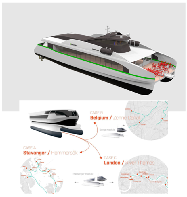
Figure 1. Image of the Stavanger Demonstrator and planned TrAM project replication studies for zero-emission, urban waterborne transport [10] https://tramproject.eu/.
2. Hydrodynamic Optimization
The hydrodynamic optimization of twin-hull vessels is a multiparametric mathematical and engineering problem with multiple objectives and constraints. We restrict herein our optimization problem to the design of small passenger catamarans and assume the specification of a certain payload capacity (for passengers and light cargo) and service speed by the end user. It is the designer’s task to find the vessel’s optimal dimensions (length, overall beam, demihulls’ beam and separation distance), hull form and displacement, the latter in dependence on the ship’s lightship weight (weight of structure, machinery and outfitting). The optimization refers in general to the ship’s calm water performance, thus to a minimization of the ship’s resistance and of required power, by maximization of the propulsive efficiency [11]. For a battery-driven, fast catamaran the hydrodynamic optimization appears even more urgent, than for a conventional high-speed craft, because the weight and space constraints imposed by the fitting of the battery racks for the required battery capacity and the fitting of e-motors driving the propellers more significantly affect the ship’s design and the associated displacement-speed-power profile.
In view of the many unknown parameters involved in the set optimization problem, which make an exhaustive exploration of the design space practically impossible, it is advisable to reduce the number of unknown parameters to the feasible, without compromising in the search for the optimal solution. This parameter reduction process is based on the designer’s experience and on background fundamental studies on the effect of certain design parameters on ship’s properties (herein mainly on ship’s weight and displacement) and on hydrodynamic performance (here total calm water resistance and its components). An increase of the demihull’s length (slenderer demihulls for a given displacement) generally leads to an increased wetted surface and of frictional resistance, while the decrease of wave resistance is modest at higher speeds, for high Froude numbers (Froude number: dimensionless speed ratio V/(g L)1/2 ) over about 0.60 [12]. An increase of the demihulls’ separation distance leads to a reduction of the interaction effect increasing the ship’s wave resistance at medium Froude numbers below about 0.60, but at the expense of a higher structural weight for the strength of the deck support structure, which leads to an increased displacement and to losses of the achieved gains in the wave resistance account. An asymmetry of the demihulls may be beneficial for wave resistance, but gains depend on the operational Froude number. An optimization of the lengthwise displacement distribution may lead to favorable (negative) demihull interaction effect, as shown in [13].
Based on this reasoning, it proves very efficient in practice to proceed with a two-stage optimization procedure, namely first a global one referring to the determination of the ship’s main dimensions and its integrated hull form characteristics, followed by a local one referring to details of the ship’s hull form and its propulsion system. Note that the terms global and local optimization are often used differently in optimization theory, namely with respect to the identification of global and local optima in optimization problems involving rapidly changing objective function(s), which is herein not the case. This optimization procedure relies on the development of a parametric model for the variation of the geometry of the ship’s hull form that can be readily accomplished by use of the software platform CAESES [14]. The multiple steps on this pathway to the selection of the final best hull form are outlined in Figure 2.
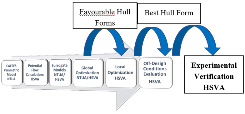
Figure 2. Multistage numerical optimization and experimental verification.
The parametric model of the hull form for the TrAM project Stavanger demonstrator was developed on the CAESES platform of Friendship Systems on the basis of 20 design parameters [15]. It offers the possibility to automatically generate smooth hull forms in the specified range of the main particulars of the demihulls along with the possibility to control and modify a series of important hull form details. A large number of about 1000 alternative hull forms was generated on the basis of four main design parameters (waterline length, demihull beam, draft and transom stern width) and assessed with the potential theory 3D panel code v-SHALLO of HSVA [16] to form the basis for the development of surrogate models (response surfaces) for the estimation of calm water resistance. Global optimization studies were carried out using the NSGA-II genetic algorithm, and two of the most promising designs were selected for more refined local optimization [15]. These hull forms were further optimized using 10 parameters of the CAESES parametric model referring to definition of the tunneled transom stern area and the propeller diameter, its position and inclination. Eight constraints referring to the inclination and fitting of the propeller shaft, as well as to propeller clearances from the hull for low vibrations were considered. Optimization runs were with HSVA’ s URANS tool FreSCo+, while focusing on the optimization of the propulsive efficiency by carefully analyzing the performance of the unique tunneled transom stern and its interaction with the fitted propellers (two CP propellers), propeller shaft, brackets and rudder (two twisted rudders). Details of the hydrodynamic optimization of the Stavanger demonstrator were elaborated in a recent paper of Papanikolaou et al. [17] and details can be omitted herein. It is, however, important to review some significant results of this research.
Numerical predictions for the resistance and the required power in the model and full-scale of the numerically optimized catamaran hull form for the specified operational profile were verified by physical tests with a 1:5.6 scaled catamaran model (5.34 m long) at the large towing tank of HSVA. The most striking result of these tests is the verification of the propulsive efficiency of the finally selected hull form, which achieved very high values of 78.2% at the design speed of 23 knots and even 80% at 27 knots (see Table 1).
Table 1. Experimentally measured hull and propulsive efficiencies for the design displacement of the Stavanger demonstrator (full scale). V: speed in knots; Fn: Froude number; t: thrust deduction fraction; w: Taylor wake fraction; ETAH: hull efficiency; ETAO: open water propeller efficiency; ETAR: relative rotative efficiency; ETAD: propulsive efficiency [34].
|
V |
Fn |
t |
w |
ΕΤΑΗ |
ΕΤΑΟ |
ΕΤΑR |
ETAD |
|
kn |
- |
- |
- |
- |
- |
- |
- |
|
08.00 |
0.243 |
0.003 |
0.002 |
0.999 |
0.782 |
0.982 |
0.762 |
|
10.00 |
0.334 |
0.021 |
0.006 |
0.985 |
0.785 |
0.974 |
0.753 |
|
13.00 |
0.394 |
0.030 |
0.032 |
1.002 |
0.764 |
0.989 |
0.757 |
|
15.00 |
0.455 |
0.015 |
0.016 |
1.001 |
0.744 |
0.994 |
0.741 |
|
17.00 |
0.516 |
0.011 |
0.000 |
0.989 |
0.753 |
1.000 |
0.745 |
|
19.00 |
0.576 |
0.017 |
-0.003 |
0.980 |
0.765 |
1.006 |
0.755 |
|
21.00 |
0.637 |
0.025 |
0.007 |
0.982 |
0.773 |
1.013 |
0.770 |
|
23.00 |
0.698 |
0.036 |
0.020 |
0.983 |
0.777 |
1.024 |
0.782 |
|
25.00 |
0.758 |
0.045 |
0.029 |
0.983 |
0.779 |
1.031 |
0.789 |
|
27.00 |
0.819 |
0.053 |
0.038 |
0.985 |
0.780 |
1.039 |
0.798 |
This remarkable and unique result deserves some brief commentary. As shown in Table 3, the tested hull had very low thrust deduction and wake fractions, high open water propeller efficiency (about 78% for over 21 knots speed) and even higher total propulsive efficiency (relative rotative efficiency over 100%). This means that the unique tunneled and longitudinally cumbered transom stern arrangement effectively reduced the required thrust and delivered propeller power at higher speeds, compared to the performance of a conventional catamaran’s stern (Figure 3). Note, also, that the wake fraction for Froude number around 0.50 (17 to 21 knots), corresponding to the “last hump” of wave resistance, was here practically zero, which effectively means that the frictional part of the wake was outweighed by the pressure part due to the generated unique transom-stern flow.
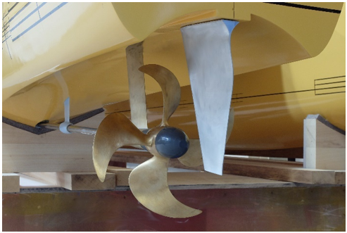
Figure 3. Close-up of the transom stern area of the tested Stavanger model, with fitted propellers, shafts, brackets and rudders [17].
The Stavanger catamaran’s hull form was twice model-tested at HSVA’ s towing tank, firstly in December 2019 for the optimized design alternative with the battery racks in the demihulls and secondly in May 2020 with a design alternative, in which the battery racks were placed on the deck area. This last design option proved better than the first one, as could be expected and numerically predicted, due to the relaxed constraints on the demihull’s minimum width (see Figure 4, the verification of the numerical prediction for the power requirement of the two design alternatives under delivery/trial conditions). These results form the basis for the final selection of the hull form, propulsive arrangements, battery capacity and electric motor power by the yard (and operator) for the desired speed profile of the Stavanger demonstrator.
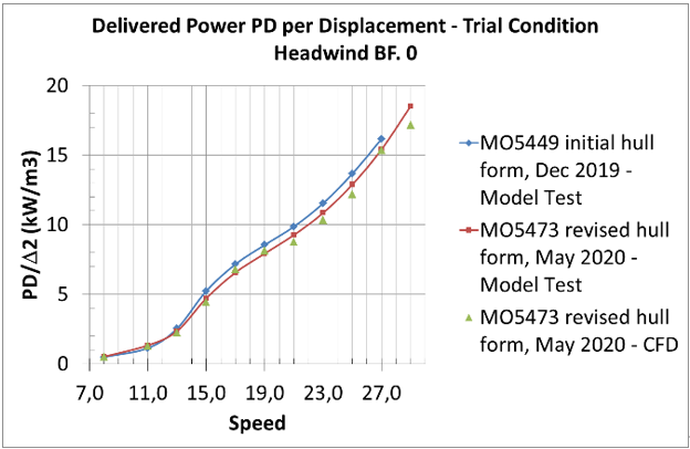
Figure 4. Prediction of rated delivered horsepower under trial conditions for the Stavanger demonstrator on the basis of model experiments and CFD calculations by HSVA (originally optimized tested in December 2019 and revised hull form tested in May 2020).
2.1. Specific Optimization Issues of Fast Catamarans
When designing a conventional, diesel-driven fast catamaran (or twin hulled vessel in general) the design option to place the main machinery in the demihulls is the most common one, assuming the availability of sufficient space and especially of sufficient demihull beam and all-around clearance for the engines. Thus, in the parametric optimization of the demihulls, a minimum demihull beam requirement over a certain hull region lengthwise (engine room) needs to be considered as constraint. Likewise for a battery driven catamaran, a minimum demihull beam requirement may be considered when the battery racks are placed in the demihulls, even though the option to place the batteries on deck is less cumbersome in terms of safety and less stringent for the hull optimization. An interesting question occurs in the hydrodynamic optimization, namely whether, for fixed demihull separation distance, the demihulls with the minimum beam are the best ones. This apparently trivial question has a more complex answer, while noting that the demihull separation distance may also be subject of optimization, even though it is often fixed as a design constraint, because of a specific deck arrangement determined by the operator and the yard))
Below in Figure 5, we can see some typical results for the calm water resistance per ton of displacement for a set of 850 parametrically generated catamaran variants against the non-dimensional beam at WL for 21kn (left) and 25 kn (right) speed.
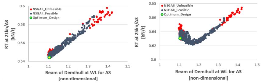
Figure 5. Typical calm water resistance per ton of displacement against non-dimensional beam at WL for 21kn (left) and 25 kn (right) [15].
The optimum design for the 23 knots speed is marked in the figures with a green circle. However, a clear differentiation between the optimization for 21 kn and 25 kn can be observed in the graphs: whereas the demihull beam of the optimum hull form for 21kn has the set minimum beam value of the demihull, this is not so when optimizing for 25 kn service speed. The reason for this, at first sight, unexpected behavior is elaborated below.
When the planned ship is operating beyond the last hump of wave resistance, the Froude number > 0.50 (in fact the speed of 21 knots for a 30 m catamaran corresponds to Froude 0.63 and 25 knots to Froude 0.75), the wave resistance part of the total resistance reduces rapidly to even less than 40% of the total resistance, whereas the % of the friction/viscous resistance part, which is dependent on the hull’s wetted surface, steadily increases. For a given displacement and length, a reduction of the demihull’ s beam and an increase of the draft generally leads to hull forms with increased wetted surface; thus, it may be expected that at higher speeds, optimal hull forms with respect to total resistance will be associated with wider demihulls, not at the set lower limits for the beam.
To demonstrate this, an additional design exploration and optimization study was conducted for the same 30 m catamaran optimized for 23 knots speed (Froude 0.69). In Figure 6, the wetted surface of parametrically generated 850 designs for a 30 m catamaran with fixed displacement and demihull length WL, but without/or much lower demihull beam constraint, as ratio to a demihull’s wetted surface (hull06), for which the beam was constrained to a low limit. It is evident that all generated designs proved to have a larger wetted surface of up to about 6.5%, when setting the low limit of the beam at 0.80. This could be expected as it is well established that for 3D solids of given volume, the sphere has the smallest wetted surface.
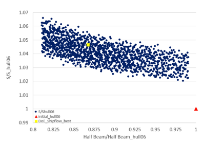
Figure 6. Wetted surface of parametrically generated 850 designs for a 30 m catamaran with fixed displacement and demihull length WL as ratio to demihull’s beam constraint; square symbol: best for beam constraint at 0.8, triangle symbol: best with beam constraint at 1.0.
Based on this finding, it is not surprising that the reduction of the catamaran’s total resistance through a decrease of the demihulls’ beam is limited, namely determined by the reduction in wave resistance, while the frictional resistance increases (Figure 7).
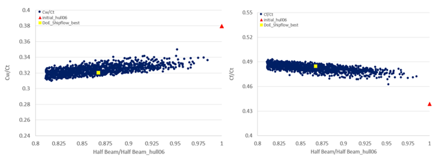
Figure 7. Percentage of wave CW (up) and frictional Cf (down) to total Ct resistance coefficient for 30 m catamaran at 23 knots (850 parametrically generated designs, square symbol: best without beam constraint, triangle symbol: best with beam constraint).
The overall outcome for the total resistance depends on the ship’s operating Froude number and the percentage value of the wave and friction to the total resistance. In Figure 8 the calculated wave patterns for the optimized hulls with (up) and without (down) demihull beam constraint are shown, in which the reduced wave resistance for the hull down is visible.
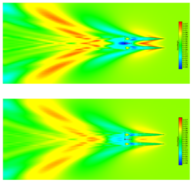
Figure 8. Wave patterns of optimized 30 m catamarans with demihull beam constraint (up) and demihull beam relaxed (down).
As could be expected, the demihull design with the relaxed demihull beam constraint, corresponding herein to a catamaran design with the battery-racks placed on deck, proves hydrodynamically superior, which is also beneficial from the point of view of safety against the risk of battery fire and explosion hazards.
References
- International Maritime Organisation (IMO). Adoption of the Initial IMO Strategy on Reduction of GHG Emission from Ships and Existing IMO Activity Related to Reducing GHG Emissions in the Shipping Sector; Note by the International Maritime Organization to the UNFCCC Talanoa Dialogue; International Maritime Organisation: London, UK, 13 April 2018.
- Serra, P.; Fancello, G. Towards the IMO’s GHG Goals: A Critical Overview of the Perspectives and Challenges of the Main Options for Decarbonizing International Shipping. Sustainability 2020, 12, 3220, doi:10.3390/su12083220.
- DNV-GL. Maritime Forecast to 2050—Energy Transition Outlook 2019.
- European Commission. Long Term Climate Strategy and Targets. Available online: https://ec.europa.eu/clima/policies/strategies/2050_en (accessed on 8 November 2020).
- European Commission. Maritime Transport Policy. Available online: https://ec.europa.eu/transport/modes/maritime_en (accessed on 8 November 2020).
- European Commission. Sustainable Transport. Available online: https://ec.europa.eu/transport/themes/sustainable_en (accessed on 8 November 2020).
- Dahl, M. Development of the World’s First Zero Emission Fast Ferry. SNAME Webinar. Available online: www.sname.org (accessed on 22 October 2020).
- Kollektivtraffikk-Foreningen: Association of Public Transport Companies in Norway. Available online:https://kollektivtrafikk.no/markedsoversikt-sjo/ (accessed on 8 November 2020).
- E-Ferry Project. Available online: http://e-ferryproject.eu/ (accessed on 8 November 2020).
- TrAM, Transport: Advanced and Modular, EU H2020 Research Project, Grant AGREEMENT No 769303, (2018–2022). Available online: https://tramproject.eu/ (accessed on 8 November 2020).
- Skoupas, S.; Zaraphonitis, G.; Papanikolaou, A. Parametric Design and Optimisation of High-Speed Ro-Ro Passenger Ships. J. Ocean Eng. 2019, 189.
- Papanikolaou, A. Ship Design- Methodologies of Preliminary Design; Springer: Berlin/Heidelberg, Germany, 2014; p. 628. ISBN 978-94-017-8751-2.
- Papanikolaou, Α.; Kaklis, Ρ.; Koskinas, C.; Spanos, D. Hydrodynamic Optimization of Fast Displacement Catamarans. In Proceedings of the 21st Symposium on Naval Hydrodynamics (ONR), Trondheim, Norway, 24–28 June 1996.
- Harries, S.; Abt, C. CAESES®—The HOLISHIP Platform for Process Integration and Design Optimization. In A Holistic Approach to Ship Design; Papanikolaou, A., Ed.; Optimisation of Ship Design and Operation for Life Cycle, Springer: Berlin/Heidelberg, Germany, 2019; Volume 1, ISBN 978-3-030-02809-1.
- Kanellopoulou, A.; Xing-Kaeding, Y.; Papanikolaou, A.; Zaraphonitis, G. Parametric Design and Hydrodynamic Optimization of a Battery-Driven Fast Catamaran Vessel. In Proceedings of the Conference on Sustainable and Safe Passenger Ships, Royal Institute of Naval Architects (RINA) and Hellenic Institute of Marine Technology (HIMT), Athens, Greece, 4 March 2020.
- Gatchell, S.; Hafermann, D.; Jensen, G.; Marzi, J.; Vogt, M. Wave Resistance Computations—A Comparison of Different Approaches. In Proceedings of the 23rd Symposium on Naval Hydrodynamics, Val de Reuil, France, 23 October 2020.
- Papanikolaou, A.; Xing-Kaeding, Y.; Strobel, H.; Kanellopoulou, A.; Zaraphonitis, G.; Tolo, E. Numerical and Experimental Optimization Study on a Fast, Zero Emission Catamaran. J. Mar. Sci. Eng. 2020, 8, 657.

