Submitted Successfully!
To reward your contribution, here is a gift for you: A free trial for our video production service.
Thank you for your contribution! You can also upload a video entry or images related to this topic.
Version Summary Created by Modification Content Size Created at Operation
1 -- 2065 2022-10-24 05:56:18 |
2 format correct + 29 word(s) 2094 2022-10-24 10:19:43 |

Video Upload Options

Do you have a full video?

Confirm

Are you sure to Delete?
Cite
If you have any further questions, please contact Encyclopedia Editorial Office.
Guo, Y.;  Liu, L.;  Ba, X.;  Lu, H.;  Lei, G.;  Sarker, P.;  Zhu, J. Rotational Magnetic Properties of Amorphous Metal Materials. Encyclopedia. Available online: https://encyclopedia.pub/entry/30805 (accessed on 27 July 2024).
Guo Y,  Liu L,  Ba X,  Lu H,  Lei G,  Sarker P, et al. Rotational Magnetic Properties of Amorphous Metal Materials. Encyclopedia. Available at: https://encyclopedia.pub/entry/30805. Accessed July 27, 2024.
Guo, Youguang, Lin Liu, Xin Ba, Haiyan Lu, Gang Lei, Pejush Sarker, Jianguo Zhu. "Rotational Magnetic Properties of Amorphous Metal Materials" Encyclopedia, https://encyclopedia.pub/entry/30805 (accessed July 27, 2024).
Guo, Y.,  Liu, L.,  Ba, X.,  Lu, H.,  Lei, G.,  Sarker, P., & Zhu, J. (2022, October 24). Rotational Magnetic Properties of Amorphous Metal Materials. In Encyclopedia. https://encyclopedia.pub/entry/30805
Guo, Youguang, et al. "Rotational Magnetic Properties of Amorphous Metal Materials." Encyclopedia. Web. 24 October, 2022.
Rotational Magnetic Properties of Amorphous Metal Materials
Edit

Amorphous metal (AM), specifically amorphous ferromagnetic metal, is considered as a satisfactory magnetic material for exploring electromagnetic devices with high-efficiency and high-power density, such as electrical machines and transformers, benefits from its various advantages, such as reasonably low power loss and very high permeability in medium to high frequency. However, the characteristics of these materials have not been investigated comprehensively, which limits its application prospects to good-performance electrical machines that have the magnetic flux density with generally rotational and non-sinusoidal features. The appropriate characterization of AMs under different magnetizations is among the fundamentals for utilizing these materials in electrical machines.

amorphous metal magnetic property characterization magnetic property measurement magnetic property modeling rotating magnetization electrical machine

1. Introduction

Electrical machines play a key role in modern industry and domestic appliances. With the requirement of reducing the consumption of fossil fuels and the emissions of carbon oxide, it is expected that most electricity will be generated by renewable energy and most drives will be electric motors. For example, electric motors are replacing the traditional internal combustion engines in cars, buses, trains, ships and even aircraft [1][2][3][4][5][6]. The space and weight allowed in these vehicles are generally limited and they often operate with harsh conditions, such as high temperature and vibration. Therefore, one of the key issues for these applications is to investigate high-efficiency, high-power-density and high-reliability electric motors. For decades, researchers have been investigating various advanced electromagnetic materials for designing such high-performance electromagnetic devices, such as high-temperature superconductors [7][8], ultra-thin electrical steel sheets [9], soft magnetic composite [10][11][12] and amorphous metal (AM) materials, specifically the amorphous ferromagnetic metal [13][14][15][16][17][18][19][20][21][22][23][24][25]. Thanks to their advantageous properties of relatively low power losses at high frequency and very high saturation flux density, the AM materials appear to be excellent candidates as the core of high-power-density electromagnetic devices, such as high-speed electrical machines and high-frequency transformers.
AM materials, solid metallic materials and usually an alloy, have a disordered atomic-scale structure, which can also be called metallic glass and glassy metal. Amorphous ferromagnetic materials can be divided into several types based on their compositions, e.g., Fe-based, Ni-based and Co-based. Of these, the Fe-based types are commonly applied as machine cores thanks to their high saturation flux density and low cost. A number of companies supply the Fe-based AMs, such as Hitachi Metals Ltd., Japan, and Henan Zhongyuan Amorphous Technology Co. Ltd., China. Compared with traditional silicon steel, AM possesses the property of much lower power loss density, e.g., only about one tenth, making it an excellent candidate for high-frequency high-power-density electromagnetic devices. Furthermore, AM has reasonably high saturation magnetic flux density, e.g., much higher than that of ferrites commonly used in high-frequency transformers. Hence, AM magnetic devices can operate at reasonably high flux density and high frequency, leading to a small volume and high power density.
Therefore, AM has garnered strong interest as the core of high-efficiency, high-power-density electrical machines [13][14][15][16][17][18][19][20][21][22][23][24][25]. In 1982, Johnson et al. [13] investigated the application of low loss AM materials in electric motors and transformers. In 1989, Fukao et al. [14] used AM to build the stator and rotor cores of a super-high-speed reluctance motor. At 48,000 rpm, the core loss of the AM machine is 80% lower than that of its silicon iron counterpart. In 1992, Jensen et al. [15] proposed an axial-flux permanent magnet brushless DC motor, which has a tape-wound amorphous core and air-gap winding and shows the advantages of higher efficiency and lower costs compared to conventional machines. In 2008, Dehlinger et al. [16] compared the stator core losses of claw-pole transverse flux machines with amorphous core and iron steel cores. Results indicated that machine efficiency and speed range can be increased by using amorphous cores. In 2011, Wang et al. [17] developed a high-speed axial-gap ferrite permanent magnet motor with an AM stator, achieving an efficiency of 93% at 14,000 rpm.
In 2013, Kolano et al. [18] designed a high-speed radial-flux permanent magnet brushless DC motor with an AM stator made of a Metglas 2605 SA1 amorphous ribbon, achieving a much smaller power loss than the silicon steel stator. In 2014, Fan et al. [19] developed a high-power-density permanent magnet motor with AM stator, achieving a volume 31% smaller or power density 45% higher than that of a baseline motor. In 2015, Ertugrul et al. [20] reported a high-speed induction electrical machine with an AM stator iron core, which is formed by laminating 0.025 mm 1k101 strips to the desired thickness and then annealing, dipping and solidifying the processes. In 2016, Tang et al. [21] presented a review of the electrical machines with amorphous alloy cores and their key technologies, such as new topologies, processing, core losses and mechanical vibrations. In 2018, Simizu et al. [22] developed a compact, high-speed (high frequency of over 1 kHz), high-power motor by applying low-loss amorphous magnetic materials. The core loss is very low, e.g., smaller than 3 W at the rated power, while that of the silicon steel machine will exceed 90 W.
In 2019, Li et al. [23] presented the modeling and performance studies of high-speed synchronous reluctance motors considering the local effect of the AA core on the electromagnetic properties. In 2020, Ismagilov et al. [24] reported the design, performance analysis, prototyping and experiment of a high-speed permanent magnet generator with the stator made by amorphous magnetic material for aerospace applications. In 2021, Fan et al. [25] conducted the performance analysis and optimum design of a high-speed induction machine with an amorphous alloy iron core.
Although many achievements regarding developing AM electrical machines have been achieved, as in [13][14][15][16][17][18][19][20][21][22][23][24][25], the results are still far from the material’s potentials. One of the major reasons is the lack of appropriate property models based on proper mechanism understandings of the material. Almost all the property data and models used for designing the electrical machines are obtained under one-dimensional (1D) alternating magnetic excitation [26], and only a very small amount of work has been carried out for the AM properties under two-dimensional (2D) magnetization.
In the core of a rotating electrical motor or the T-joint of a three-phases transformer, the tip of magnetic flux density vector generally forms a 2D or even three-dimensional (3D) rotational irregular loop. It has been found that the magnetic material behaves very differently under the 1D alternating excitation and 2D/3D rotational excitation, and the conventional models cannot correctly predict the material properties under these irregular rotating flux density patterns [27][28][29][30][31][32][33][34].
In summary, for achieving the best use of material potentials, the AM property characteristics should be investigated under the actual conditions that electromagnetic devices usually operate in. This entry aims to present an overview of the characterization of AM materials under 2D rotational magnetizations based on the authors’ research as well as other scholars’ relevant work in this area.

2. Measurement of Rotational Magnetic Properties of Amorphous Magnetic Materials

2.1. Measuring System of 2D Magnetic Properties

Since the first measurement of 2D rotational magnetic properties was reported by Baily in 1896 [27], a number of 2D rotational property measuring systems and techniques have been developed [28][29][30]. Of these measurement systems, the square sample single sheet tester, which was developed by Brix et al. [31], has proven to be the most favorable, thanks to its high control flexibility on rotating magnetic field patterns, outstanding uniformity of magnetic flux density distribution in the sample and, hence, high measurement accuracy.
Led by J. Zhu, the University of Technology Sydney (UTS) Magnetic Testing Group developed a square sample single sheet tester [32], which has been used to measure different magnetic materials. This tester is cooperated via a computerized digital signal process system, and it is able to measure the B-H relations as well as the core losses under 1D alternating fluxes in any specific direction, or 2D circularly and elliptical rotating fluxes with different axis ratios. Figure 1 shows the schematic diagram of the square single sheet tester and the whole system. The tester contains yokes made up of laminated grain-oriented electrical sheets, and the yoke shapes were designed to form four wedge-type magnetic poles. Two excitation coil groups are wound around the X- and Y-axes, and each group has two coils, which are connected in series. A square sample of magnetic material is installed in the middle of the tester.
Figure 1. Principle diagram of the 2D rotating magnetic property test system: (a) schematic diagram, (b) single sheet tester for square sample and (c) positions of sample and H search coils.
The 2D magnetic field in the sample is produced with the currents flowing in the two sets of excitation coils discharged on X- and Y-axes, respectively. The excitation currents are provided by two power amplifiers. Through controlling the magnitudes, the phase angles and waveforms of the excitation currents, any 1D or 2D magnetic flux density vector can be produced, e.g., a 1D alternating flux density inclined at a specific angle from the X- or Y-axis, a circularly or elliptically rotational flux density or a flux density of any specified locus. Two dedicated differential amplifiers with low and high pass filters are used for the feedback control of the flux density components on the axes. The function generation and data acquisition are both realized by a PC-based digital signal processing system.

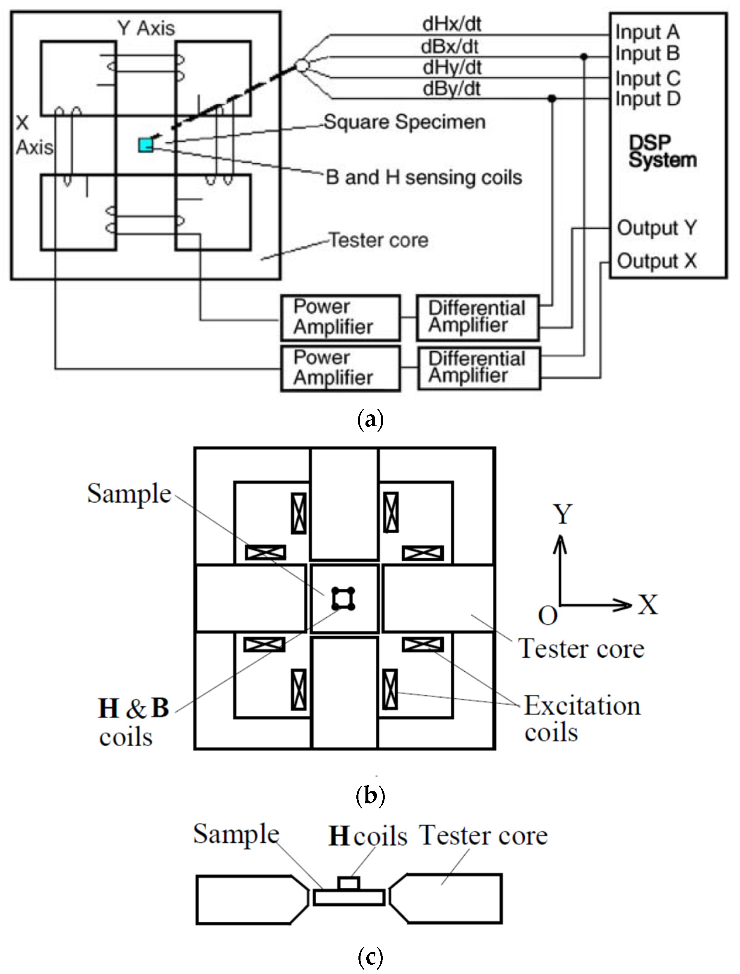
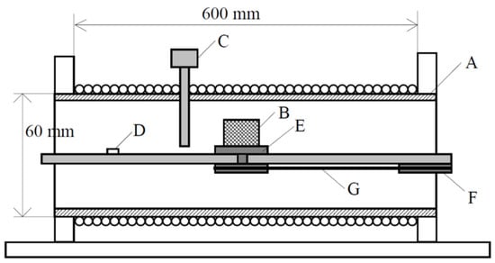
2.2. Material Sample for 2D Measurement

As shown in Figure 1, a square material sample is placed in the tester center, where a magnetic field is generated by the X- and Y-axes excitation currents. In researchers' study [33], the sample was fabricated by cutting the AMCC-320 amorphous core, which is composed of amorphous 1k101 strips. The square sample is of 50 mm length, 50 mm width and 0.86 mm thickness and consists of an amorphous strip stack of 25 μm in thickness. The stacking factor is about 0.85.

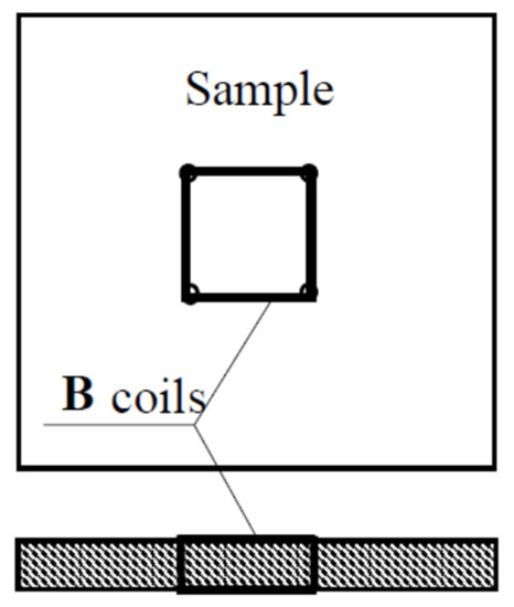
2.3. Measurement of 2D Magnetic Field

To acquire the B-H relation and associated core loss, the magnetic flux density inside the sample and the magnetic field strength on the surfaces should be measured accurately. As shown in Figure 1, the magnetic flux density and field strength in the sample can be acquired by the B and H sensing coils connected to the sample. Fifteen turns of enamel insulated copper wire of 0.1 mm in diameter are threaded through four small holes to form a B coil on each axis, as illustrated in Figure 2. The perforation is tiny and has little effect on the magnetic field distribution inside the sample. For accurate measurement, the flux density should be uniformly distribution in the sample, which is realized by optimal design of the tester, particularly the shape and dimensions of the magnetic poles.
Figure 2. Arrangement of 2D B coils.
The magnetic flux density on one axis can be computed by
B i = 1 N B i A B i V B i d t   ( i = x , y )
where ABi is the cross-sectional area, NBi is the turns number and VBi the induced voltage across the terminals of the B-coil on the axis.
The surface H coils, as shown in Figure 1c, are applied to measure the 2D magnetic field strength. According to the Ampere’s law, the field strength on the surface would be equal to that just inside the sample if there were no surface currents. The H-sensing coils can be fabricated very thinly, and they can be attached on the sample surface and thus the true value of the field strength inside the sample can be acquired. The magnetic field strength component on one axis can be computed by
H i = 1 μ 0 K H i V H i d t   ( i = x , y )
where VHi is the induced voltage across the terminals of the H-coil on the axis, μ0 the permeability of air and KHi the coil coefficient, which is determined by calibrating a solenoid as shown in Figure 3, where A is the frame, B is the H coils to be calibrated, C is the Gauss meter probe, D is the connector for outputting the coil terminal voltage signals, E is the turn table for placing the coils and F and G are the wheel rubber bands for adjusting the coil orientation.
Figure 3. Solenoid for calibrating H sensing coils.
It should be noted that this tester can also be used to measure the 1D alternating magnetic properties. When only the X-axis or Y-axis excitation current is applied, the H and B vectors are constrained in the X or Y direction, and the measured B-H relation would be the traditional B-H hysteresis loops.
The measurement of rotational magnetic properties is mainly conducted under the so-called circularly rotating magnetization, i.e., the excitation currents of the X- and Y- axes are controlled to form a rotating flux density vector of constant magnitude and speed. Sometimes, measurements under elliptically rotating magnetization are also carried out, e.g., with different ratios of the minor-axis to major-axis magnitudes of flux density. The magnetic properties are usually measured with various frequencies and various maximum flux densities.

References

  1. Zhu, Z.Q.; Howe, D. Electrical Machines and Drives for Electric, Hybrid, and Fuel Cell Vehicles. Proc. IEEE 2007, 95, 746–765.
  2. Sun, X.; Shi, Z.; Lei, G.; Guo, Y.; Zhu, J. Analysis and Design Optimization of a Permanent Magnet Synchronous Motor for a Campus Patrol Electric Vehicle. IEEE Trans. Veh. Technol. 2019, 68, 10535–10544.
  3. Ritari, A.; Vepsäläinen, J.; Kivekäs, K.; Tammi, K.; Laitinen, H. Energy Consumption and Lifecycle Cost Analysis of Electric City Buses with Multispeed Gearboxes. Energies 2020, 13, 2117.
  4. Guo, Y.G.; Jin, J.X.; Zhu, J.G.; Lu, H.Y. Design and Analysis of a Prototype Linear Motor Driving System for HTS Maglev Transportation. IEEE Trans. Appl. Supercond. 2007, 17, 2087–2090.
  5. Reusser, C.A.; Young, H. Full Electric Ship Propulsion based on a Flying Capacitor Converter and an Induction Motor Drive. In Proceedings of the International Conference on Electrical Systems for Aircraft, Railway, Ship Propulsion and Road Vehicles, Aachen, Germany, 3–5 March 2015; pp. 170–176.
  6. Tom, L.; Khowja, M.; Vakil, G.; Gerada, C. Commercial Aircraft Electrification—Current State and Future Scope. Energies 2021, 14, 8381.
  7. Masson, P.; Luongo, C. High Power Density Superconducting Motor for All-Electric Aircraft Propulsion. IEEE Trans. Appl. Supercond. 2005, 15, 2226–2229.
  8. Jin, J.X.; Zheng, L.; Guo, Y.; Zhu, J.G.; Grantham, C.; Sorrell, C.C.; Xu, W. High-Temperature Superconducting Linear Synchronous Motors Integrated with HTS Magnetic Levitation Components. IEEE Trans. Appl. Supercond. 2012, 22, 5202617.
  9. Enokizono, M.; Wakabayashi, D.; Soda, N.; Tsuchida, Y.; Ueno, S.; Oka, M. High Power Density and High Efficiency of High-Speed Motor. In Proceedings of the 2020 International Conference on Electrical Machines (ICEM), Gothenburg, Sweden, 23–26 August 2020; pp. 170–176.
  10. Guo, Y.; Zhu, J.G.; Dorrell, D.G. Design and Analysis of a Claw Pole Permanent Magnet Motor with Molded SMC Core. IEEE Trans. Magn. 2009, 45, 4582–4585.
  11. Liu, C.; Lei, G.; Wang, T.; Guo, Y.; Wang, Y.; Zhu, J. Comparative Study of Small Electrical Machines with Soft Magnetic Composite Cores. IEEE Trans. Ind. Electron. 2016, 64, 1049–1060.
  12. Du, W.; Zhao, S.; Zhang, H.; Zhang, M.; Gao, J. A Novel Claw Motor with Soft Magnetic Composites. IEEE Trans. Magn. 2021, 57, 8200904.
  13. Johnson, L.A.; Cornell, E.P.; Bailey, D.J.; Hegyi, S.M. Application of Low Loss Amorphous Metals in Motors and Transformers. IEEE Trans. Power Appar. Syst. 1982, 7, 2109–2114.
  14. Fukao, T.; Chiba, A.; Matsui, M. Test results on a super-high-speed amorphous-iron reluctance motor. IEEE Trans. Ind. Appl. 1989, 25, 119–125.
  15. Jensen, C.C.; Profumo, F.; Lipo, T.A. A Low-Loss Permanent-Magnet Brushless DC Motor Utilizing Tape Wound Amorphous Iron. IEEE Trans. Magn. 1992, 28, 646–651.
  16. Dehlinger, N.; Dubois, M.R. Clawpole Transverse Flux Machines with Amorphous Stator Cores. In Proceedings of the 2008 18th International Conference on Electrical Machines, Vilamoura, Portugal, 6–9 September 2008; pp. 1–6.
  17. Wang, Z.; Enomoto, Y.; Masaki, R.; Souma, K.; Itabashi, H.; Tanigawa, S. Development of a High Speed Motor Using Amorphous Metal Cores. In Proceedings of the 8th International Conference on Power Electronics-ECCE Asia, Jeju, Korea, 30 May–3 June 2011; pp. 1940–1945.
  18. Kolano, R.; Krykowski, K.; Kolano-Burian, A.; Polak, M.; Szynowski, J.; Zackiewicz, P. Amorphous Soft Magnetic Materials for the Stator of a Novel High-Speed PMBLDC Motor. IEEE Trans. Magn. 2012, 49, 1367–1371.
  19. Fan, T.; Li, Q.; Wen, X. Development of a High Power Density Motor Made of Amorphous Alloy Cores. IEEE Trans. Ind. Electron. 2014, 61, 4510–4518.
  20. Ertugrul, N.; Hasegawa, R.; Soong, W.L.; Gayler, J.; Kloeden, S.; Kahourzade, S. A Novel Tapered Rotating Electrical Machine Topology Utilizing Cut Amorphous Magnetic Material. IEEE Trans. Magn. 2015, 51, 8106006.
  21. Tang, R.; Tong, W.; Han, X. Overview on Amorphous Alloy Electrical Machines and Their Key Technologies. Chin. J. Electr. Eng. 2016, 2, 1–12.
  22. Simizu, S.; Ohodnicki, P.R.; McHenry, M.E. Metal Amorphous Nanocomposite Soft Magnetic Material-Enabled High Power Density, Rare Earth Free Rotational Machines. IEEE Trans. Magn. 2018, 54, 8202505.
  23. Li, Z.; Pei, Y.; Chai, F.; Hu, H.; Wu, Y.; Yu, Y. Accurate Modeling and Performance Analysis of Synchronous Reluctance Motor Considering Amorphous Alloy Properties. In Proceedings of the 2019 22nd International Conference on Electrical Machines and Systems (ICEMS), Harbin, China, 11–14 August 2019; pp. 1–6.
  24. Ismagilov, F.R.; Papini, L.; Vavilov, V.E.; Gusakov, D.V. Design and Performance of a High-Speed Permanent Magnet Generator with Amorphous Alloy Magnetic Core for Aerospace Applications. IEEE Trans. Ind. Electron. 2020, 67, 1750–1758.
  25. Fan, Z.; Yi, H.; Xu, J.; Xie, K.; Qi, Y.; Ren, S.; Wang, H. Performance Study and Optimization Design of High-Speed Amorphous Alloy Induction Motor. Energies 2021, 14, 2468.
  26. Hagihara, H.; Tanaka, M.; Takahashi, Y.; Fujiwara, K.; Ishihara, Y. Standard Measurement Method for Magnetic Properties of Fe-Based Amorphous Magnetic Materials. IEEE Trans. Magn. 2014, 50, 6100604.
  27. Baily, F.G. The Hysteresis of Iron and Steel in a Rotating Magnetic Field. Philos. Trans. R. Soc. 1896, 187, 715–746.
  28. Sievert, J. Recent Advances in the One- and Two-dimensional Magnetic Measurement Technique for Electrical Sheet Steel. IEEE Trans. Magn. 1990, 26, 2553–2558.
  29. Guo, Y.; Zhu, J.G.; Zhong, J.; Lu, H.; Jin, J.X. Measurement and Modeling of Rotational Core Losses of Soft Magnetic Materials Used in Electrical Machines: A Review. IEEE Trans. Magn. 2008, 44, 279–291.
  30. Sievert, J. Two-dimensional Magnetic Measurement-History and the Achievements of the Workshop. Przeg. Elektrot. 2011, 87, 2–10.
  31. Brix, W.; Hempel, K.; Schroeder, W. Method for the measurement of rotational power loss and related properties in electrical steel sheets. IEEE Trans. Magn. 1982, 18, 1469–1471.
  32. Zhu, J.G.; Ramsden, V.S. Two Dimensional Measurement of Magnetic Field and Core Loss Using a Square Specimen Tester. IEEE Trans. Magn. 1993, 29, 2995–2997.
  33. Sarker, P.C.; Guo, Y.; Lu, H.Y.; Zhu, J.G. Measurement and Modeling of Rotational Core Loss of Fe-Based Amorphous Magnetic Material Under 2-D Magnetic Excitation. IEEE Trans. Magn. 2021, 57, 8402008.
  34. Brix, W.; Hempel, K.; Schulte, F. Improved method for the investigation of the rotational magnetization process in electrical steel sheets. IEEE Trans. Magn. 1984, 20, 1708–1710.
More
Information
Contributors MDPI registered users' name will be linked to their SciProfiles pages. To register with us, please refer to https://encyclopedia.pub/register : , , , , , ,
View Times: 426
Revisions: 2 times (View History)
Update Date: 24 Oct 2022
1000/1000
Video Production Service