1. Conventional Dry Magnetic Separator
The conventional dry magnetic separator (CDMS) utilizes the centrifugal force provided by the drum to throw away the gangue. It is mainly used to discard the surrounding rocks mixed in the ore to restore the geological grade of the bulk magnetic materials. The bulk magnetic materials have a poor dissociation degree, which means that the amount of gangue thrown by the separator is limited and contains some valuable minerals.
1.1. Magnetic Pulley
Magnetic pulleys, also known as magnetic drums, are used in mineral processing plants for pre-discarding tailings from bulk ores. These pulleys play an important role in energy saving and consumption reduction in beneficiation plants
[1]. With the continuous deep mining of iron ore resources, the grade of mined ore decreases annually, the supply of raw ores is now unable to meet production demands, and the service life of mines is gradually shortened. Lu et al.
[2] successfully applied magnetic pulleys in the Midi beneficiation plant in China, which resulted in good economic profits. Specifically, this device discarded 6.77% of tailings and improved the ore grade by 1.27%. With the rapid development of permanent magnetic materials, the technical performance of magnetic pulleys has been improved recently. A magnetic pulley with NdFeB magnets increases the induced magnetic strength of the sorting area on the drum surface from 0.15 T–0.18 T to more than 0.4 T, with the highest point reaching 0.5 T, and greatly improved the depth of the magnetic field compared with the previous one. In addition, the upper limit of the particle size handled by the magnetic pulley increases from 75 mm to over 350 mm, resulting in the wide application of this tool in industrial production.
Magnetic pulleys come in many types, with the main differences lying in their magnets, materials, and separating precision. For instance, the SR-E magnetic drum developed by Eriez Corporation (PA, USA), uses a permanent-magnetic–electromagnetic compound magnetic system, with a cylinder length of 2438 mm, diameter of 2433 mm, processing capacity of 500–600 t/h, maximum feed size of 350 mm, and magnetic field strength of 0.20 T to 0.5 T
[3]. The drum speed, diameter, field strength, and poles of the magnetic drums developed by Sala Corporation (Västmanland, Sweden) can be set according to the process requirements, and the drums have a maximum drum diameter of 1500 mm and maximum material size of 300 mm
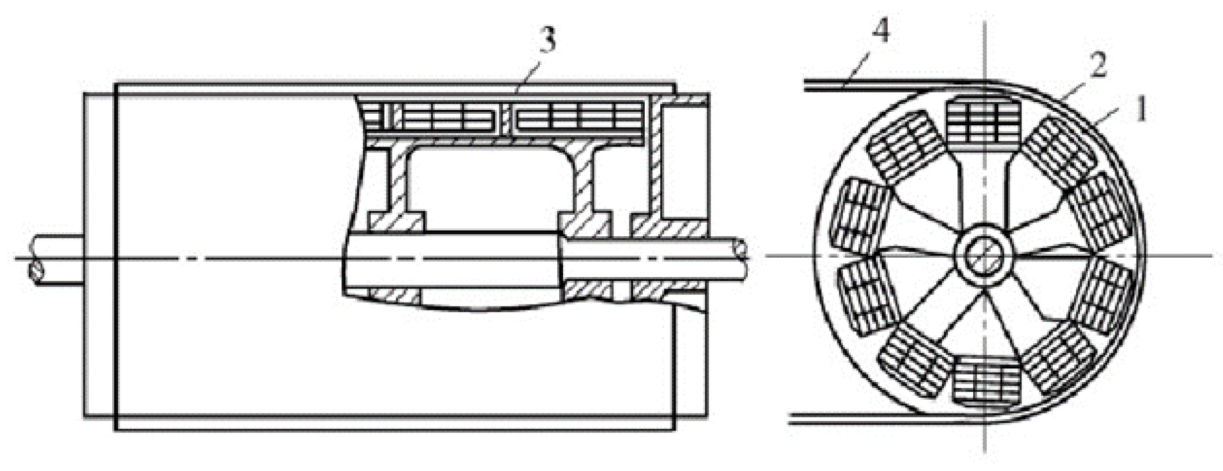
[4][5]. The structure of the CT1416 magnetic pulley developed by BGRIMM technology group is shown in
Figure 1. The maximum size of ore treated by this device is 350 mm, and its unit capacity is 450 t/h. The successful application of this separator in the Zhangjiawa iron ore (mine in China) improved the concentrate grade by 2.95 percentage points
[4]. The group also further developed the CT1627 magnetic pulley, which currently holds the record of being the largest magnetic pulley in the world. This device has a large-scale mechanical structure and a large pole surface magnetic system, and the induced magnetic strength of its cylinder surface can reach 500 mT. The CT1627 magnetic pulley also has a maximum sorting size of 400 mm and a processing capacity of 4500 t/h. After 7 months of industrial operation, this device recovered approximately 460,000 t of ore with a grade of 20% to 30%
[6].
Figure 1. Schematic diagram of CT series magnetic pulley structure. 1—multipole magnetic system; 2—cylinder; 3—magnetic conductor; 4—belt
[4].
1.2. Dry Drum Magnetic Separator
In the 1980s, Ball-Nortony developed the first electromagnetic drum magnetic separator, which was then widely used for magnetic iron removal. In the late 1980s, following in-depth research on rare earth permanent magnetic materials and the magnetic system structure, the drum magnetic separator gradually realized permanent magnetization. The Swedish company Sala produced the first permanent magnetic drum magnetic separator in 1989
[7]. At present, manufacturers of drum-type magnetic separators are leaning toward the development of large-scale drums, high field strength, and multiple drums in series
[8]. In the direction of large scale, Eriez Corporation (PA, USA) developed a magnetic separator, with a maximum drum diameter of 1219 mm and drum length of 3048 mm. Meanwhile, the magnetic separator developed by Sala Corporation (Västmanland, Sweden) has a maximum drum diameter of 1200 mm, drum length of 3000 mm, and equipment capacity of 500 t/h. The ROXON magnetic separator developed by Kern Engineering Company in Finland has a drum diameter of 1200 mm, drum length of 3000 mm, and equipment processing capacity of 400 t/h. The development of a larger dry magnetic separator can help improve the processing capacity and efficiency of the equipment and reduce its energy consumption
[9]. In the direction of high field strength, some scholars began to study the magnetic circuit in the 1970s, published the first research on the magnetic circuit of a strong permanent magnetic field in 1974, and then developed the first medium-field strong permanent drum magnetic separator with a magnetic field strength of 0.5 T. Soon after, the second generation of permanent drum magnetic separators was developed with a magnetic field strength of 0.7 T
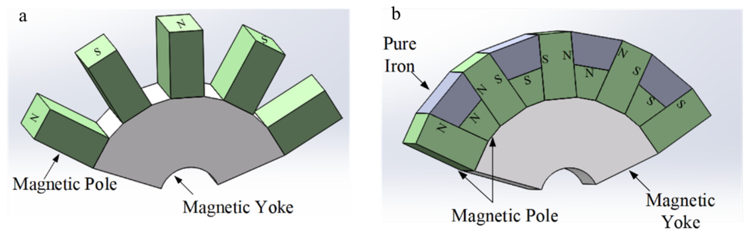
[10]. Two types of magnetic system structures are commonly used in drum magnetic separators, namely the open magnetic system structure and the extruded magnetic system structure, as shown in
Figure 2
Figure 2. (a) Open magnetic system structure; (b) extruded magnetic system structure.
The open magnetic system has a simple structure and is mainly used for the sorting of strongly magnetic ores. This system has two basic designs, called radial and axial configurations. In a radial configuration, the polarity of permanent magnets alternates across the drum width, whereas in an axial arrangement, the poles alternate along the circumference. The radial configuration is beneficial in the recovery of strongly magnetic material, whereas the axial configuration is used in situations where the grade of the concentrate is particularly important. The tumble motion of particles over the rows of the magnet with alternating polarity releases the entrained non-magnetic particles, hence improving the grade of magnetic concentrate. In addition, auxiliary poles can be added to the two main magnetic poles in the open magnetic system to generate field strength formed through the three poles superimposed in space and improve the strength and depth of action of the magnetic field. However, the magnetic lines of force in the open magnetic system are relatively scattered, thereby introducing challenges in achieving a very high magnetic field strength. At present, the magnetic field strength at the drum surface under this magnetic system structure cannot easily exceed 0.75 T, hence preventing the recovery of weak magnetic minerals, such as hematite and manganese ore
[11][12]. By contrast, the emergence of the extruded magnetic system further increased the magnetic field strength on the surface of the drum. The principle of this system is to arrange the magnetic poles of the same polarity next to one another to concentrate the magnetic lines of force in a small space, and then export them through a magnetic conductive medium to produce a high magnetic field strength on this medium. However, the depth of the magnetic field action has insufficient depth. In the direction of multiple drums in series, the current frame structure of the drum magnetic separator is suitable for installing multiple drums to form two-, three-, and four-drum magnetic separators, thereby realizing the integration of roughing, selecting, and sweeping operations; improving the processing capacity of the equipment; shortening the process; and saving space. East and Mineral Processing Machine, Inc., in Japan developed the TY-6E-2 type magnetic separator, which comprises four magnetic drums in series, of which the first drum is used for coarse separation, the second drum is used for sweeping, and the third and fourth drums are used for concentration. Using this device to separate alluvial iron ore can obtain a concentrate grade of 57% to 61%. Meanwhile, the DA-BW and DA-3B magnetic separators manufactured by Mitsubishi Electric Corporation (Tokyo, Japan) and Mitsubishi Metals Corporation (Tokyo, Japan) are assembled with double and triple drums, respectively, which can greatly improve their processing capacity and sorting performance
[13].
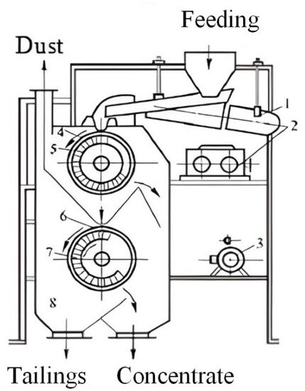
Although dry drum magnetic separators come in many types, their working principles are similar, and they are widely used for sorting magnetic ores. As shown in
Figure 3, the CTG magnetic separator mainly comprises a drum, magnetic system, sorting box, feeder, and driving device. The sorting principle of this device is that when minerals reach the surface of the drum through the feeding device, the non-magnetic particles enter the tailing area under the action of gravity, centrifugal force, and friction, whereas the magnetic minerals are adsorbed on the surface of the drum due to magnetic force and fall into the concentrate area under the action of inertia and gravity when the drum rotates to the area without magnetic field
[14]. Yin et al.
[15] developed the CTG-1030 drum magnetic separator with a large magnetic wrap angle composite pole set and extruded magnetic system structure, which enhances both the magnetic field force and depth of magnetic field action on the drum surface. Using this device to sort raw ore with a magnetic iron content of 3% and particle size of < 3 mm can result in a good index of 11.40% concentrate grade, 0.7% tailing grade, and 80.29% recovery.
Figure 3. Structure diagram of CTG permanent magnet double-barrel dry magnetic separator: 1—electric vibration feeder; 2—stepless governor; 3—electric motor; 4—upper roller; 5, 7—circular magnetic deficiency system; 6—lower roller; 8—box
[14].
1.3. Dry Permanent Roll Magnetic Separator
The roll magnetic separator can be divided into electromagnetic induction roll and permanent roll magnetic separator according to the material of the magnetic system used. Compared with the electromagnetic roller magnetic separator, the permanent roll magnetic separator has more energy-saving features, a simpler structure, and a smaller floor space
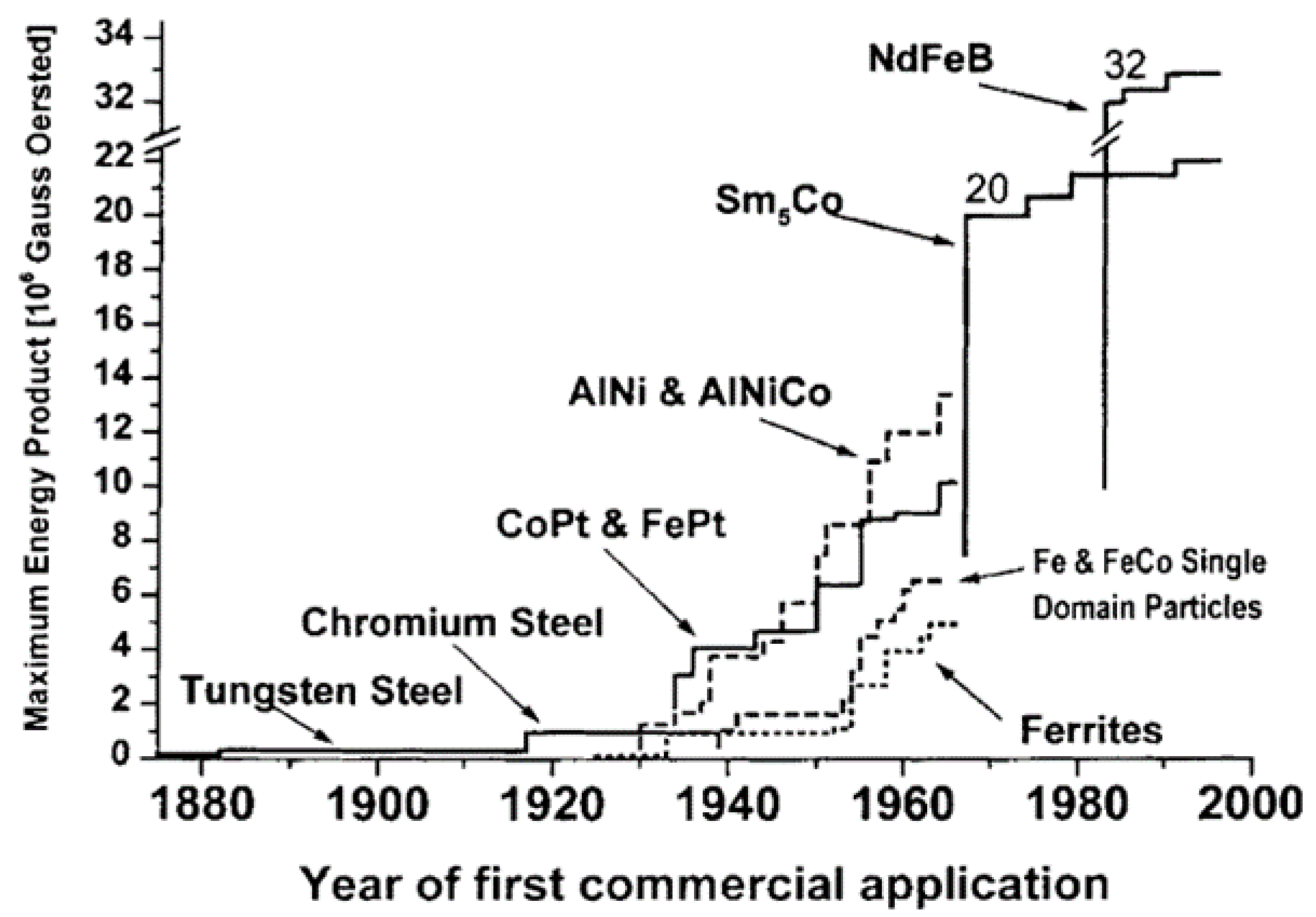
[16]. Due to the continuous development of rare earth permanent magnet materials in recent years, as shown in
Figure 4, the surface magnetic field strength of the permanent roll magnetic separator can easily reach more than 1 T, thereby gradually replacing the electromagnetic induction roller
[17].
Figure 4. History of magnetic materials used in permanent magnetic separators
[17].
Research on the permanent roll magnetic separator started as early as the 1970s, whereas related industrial applications began in the 1980s, starting from dry iron production from nonmetallic ores to the pre-sorting of weakly magnetic ores with coarse particle size
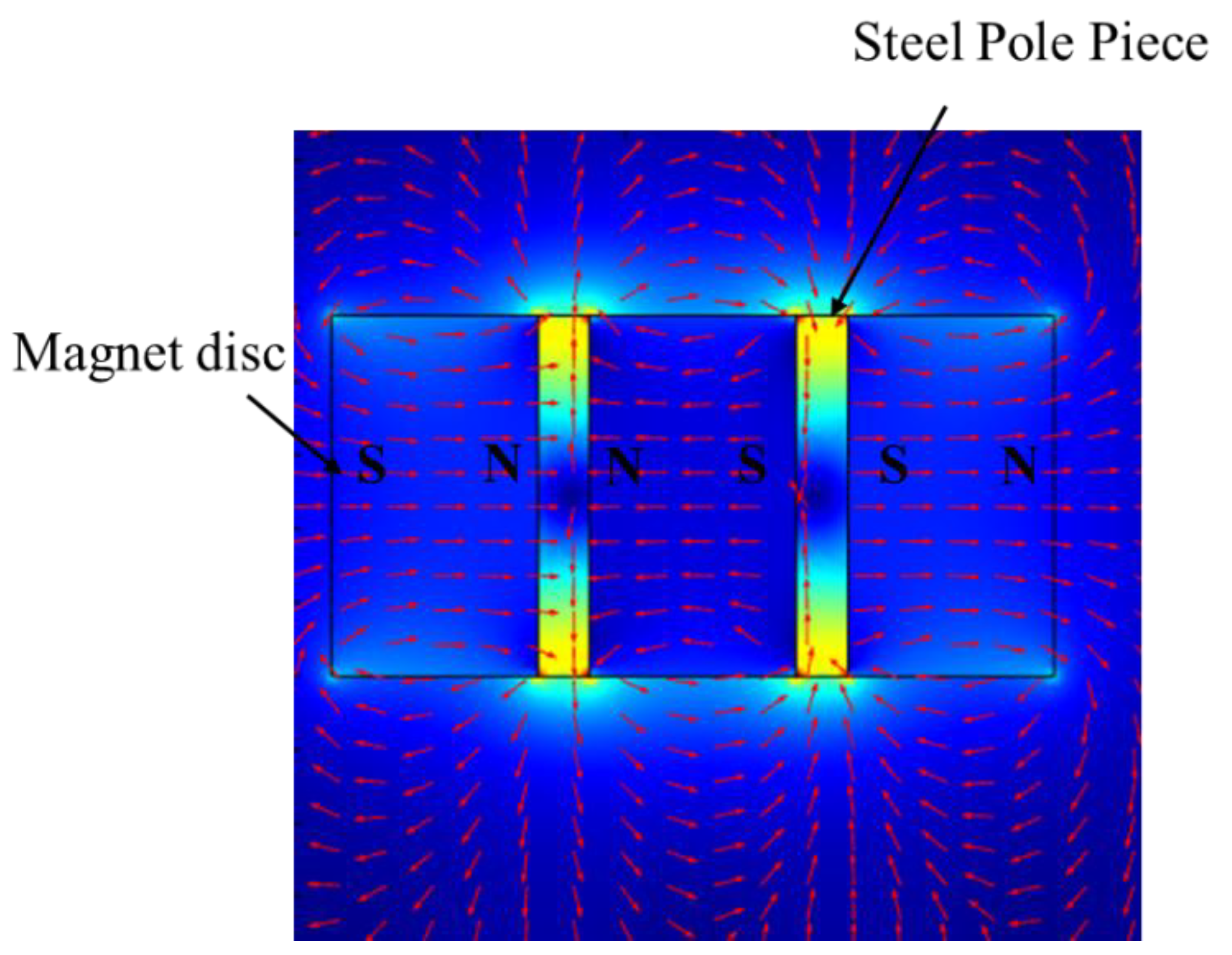
[18]. The permanent roll magnetic separator comprises permanent magnet discs or rings interleaved with mild steel discs, as shown in
Figure 5. Due to the specificity of the magnetic system structure, the magnetic field distribution of the separator is extremely uneven, and the magnetic line density on the roll surface is large, with high magnetic field strength and gradient
[19].
Figure 5. Generation of magnetic field on a roll magnetic separator.
Due to the rapid decay of the magnetic field strength on its surface, the roll magnetic separator is often used in conjunction with a thin belt. The separation principle of the roll magnetic separator is that the material is fed to the top of the belt and comes to the magnetic roller with the rotation of the belt, the magnetic particles are adsorbed on the surface of the magnetic roller and brought to the concentrate area, and the gangue is brought to the tailing area by centrifugal force and gravity, so as to realize the separation of magnetic material and gangue particles. The factors affecting the sorting performance of the roller magnetic separator can be categorized as follows: feed properties, design parameters, and operating parameters. The specific factors are shown in
Figure 6 [20].
Figure 6. The influences of rare earth roll magnetic separator process parameters
[20].
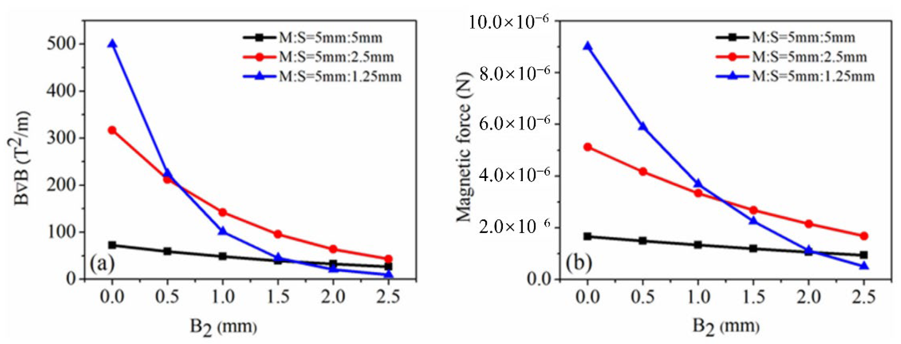
The magnet-to-steel disc thickness ratio (MSTR) is the key parameter of roll design that affects the strength and depth of the magnetic field. G.T. Mohanraj explored the magnetic field distribution of rolls with the help of the FEMM simulation software for different MSTRs. The simulation results are shown in Figure 7.
Figure 7. (
a) Change in BB (force index) as a function of B2 for different M:S ratios; (
b) change in magnetic force as a function of B2 for different M:S ratios
[20].
The results show that as the magnet-to-steel disc thickness ratio (MSTR) increases, the magnetic field gradient on the roll surface and the magnetic force on the magnetic particles both increase, but the magnetic field significantly decreases as distance increases. Sunil Kumar Tripathy
[21] investigated the effect of magnetic roll parameters on the sorting of hematite with a fine particle size, and experimental results show that the magnetic field strength on the roll surface differs at the same MSTR (4:1, 8:2, and 12:3) but at different ring thicknesses of 1.05 T, 1.24 T, and 1.27 T, respectively. Gulsoy and Orhan achieved better iron removal for coarse-grained feldspar with a high MSTR in their test of feldspar removal with permanent magnet rolls
[22]. The above results show that improving the MSTR and the thickness of magnetic and steel rings can help to enhance the magnetic field strength. The choice of MSTR is closely related to the properties of the material to be selected, and a suitable MSTR is conducive to improving the sorting effect of the separator.
Dry permanent roll magnetic separators are widely used to remove iron in non-metal ore or to pre-separate paramagnetic ore and have yielded good economic benefits. For example, the high-force permanent magnetic separator developed by INPROSYS, Inc., whose roll comprises 4 mm and 1 mm thick permanent magnetic rings and iron sheets arranged in a staggered manner, can reach a field strength of 2.2 T on the roll surface, but its field strength drops to 1 T at 2 mm from the roll surface. This separator handles a wide range of materials (about 20 mm to 0.074 mm) and has low energy consumption, requiring only a few watts of drive power, and a large processing capacity; thus, it has received wide usage in the United States, Australia, and Canada
[23]. The Permroll permanent magnetic roll separator developed by Bettman Mining Equipment Supply Group, in South Africa, can reach a 1.2 T magnetic field strength on the surface of the roller, is light in weight (0.5 tons), consumes low power, processes a wide range of particle sizes (generally <3 mm), and is currently being sold to 25 countries
[24]. Similarly, the CRIMM series permanent roll magnetic separator developed by the Changsha Institute of Mining and Metallurgy in China has a magnetic roller material made of neodymium (NdFe-B) and DT4 pure iron and can reach a magnetic roller surface field strength 1.4 T. This device also has a processing size range of 20 mm to 0.074 mm and processing capacity of 0.5 t/h–8 t/h. This device performs well in the selection process of Yunnan Huanian limonite ore in China; when the raw ore grade is 46%, a single sorting can obtain a concentrate grade of more than 50% and a more than 80% recovery rate
[25]. The YCG series magnetic separators developed by the Maanshan Mining Research Institute in China have been used to address the limitations of coarse-grain permanent roll magnetic separators and are considered the ideal equipment for sorting coarse-grain weakly magnetic minerals. This device has a roll surface field strength that can reach 1.4 T and a processing particle size range of 75 mm to 6 mm. This device was used to modify the gravity separation plant of the Shanghai Meishan Mining Company in China and to replace the jigger. Results show that when the feed grade ranges from 24% to 26%, a concentrate grade ranging from 32% to 34% and a tailing grade ranging from 10% to 12% can be obtained after separation, which leads to the recovery of 85,000 tons of coarse concentrate more than the jigger in a year and a revenue of CNY 3.6 million
[26].
2. Dry Magnetic Separator with Improved Magnetic System
With the rapid development of rare earth permanent magnetic materials and agglomeration technology
[27][28], the magnetic system can obtain high magnetic field strength without relying on electromagnetism, and the current dry magnetic separators have basically realized permanent magnetization. A magnet composed of NdFeB has the advantages of high magnetic field strength, simple structure, and low production energy consumption, but due to the high magnetic field strength, it easily produces the magnetic agglomeration effect, so the magnetic system design of this type of magnetic separator is often different from the conventional magnetic separator. For example, the CXY cylindrical rare earth permanent magnetic separator with a wiggling magnetic system designed by Xu et al. has a magnetic system made of NdFeB magnet material, and the magnetic induction of the drum surface is 0.3~0.8 T
[29]. The most important feature of this device is that the magnetic system can oscillate back and forth. Therefore, the magnetic minerals slide on the surface of the drum when sorting, which makes the material become loose and effectively cleans sticky material. In addition, the dynamic magnetic field separator developed by Zhao et al.
[30][31] uses asynchronous rotation between the magnetic system and the drum, which generates a high-frequency alternating magnetic field on the surface of the drum, making the tumbling times of mineral particles several times higher than the conventional magnetic separators, and this magnetic separator has achieved better results in the magnetic separation experiments of fine-grained minerals. In addition, Wang et al.
[32] designed the CTFG-type powder ore dry magnetic separator. The sorting principle is shown in
Figure 8. The drum and magnetic system rotate in reverse, and the magnetic chain rolls, shakes, and throws at high frequency on the drum, which greatly throws away the pebble particles entrapped in the powder ore.
Figure 8. Separation principle of CTFG dry magnetic separator for fine ore
[32] 1—vibration feeder; 2—ultra-thin transport belt; 3—tail wheel; 4—concentrate scraper; 5—concentrate bucket; 6—tailings bucket; 7—ore plate; 8—rotating magnetic system.
 +1 credit