Submitted Successfully!
To reward your contribution, here is a gift for you: A free trial for our video production service.
Thank you for your contribution! You can also upload a video entry or images related to this topic.
Version Summary Created by Modification Content Size Created at Operation
1 -- 3277 2022-08-25 14:21:49 |
2 update references and layout + 3 word(s) 3280 2022-08-26 03:32:04 | |
3 update references and layout Meta information modification 3280 2022-08-26 03:34:04 |

Video Upload Options

Do you have a full video?

Confirm

Are you sure to Delete?
Cite
If you have any further questions, please contact Encyclopedia Editorial Office.
Morkvenaite-Vilkonciene, I.;  Bucinskas, V.;  Subaciute-Zemaitiene, J.;  Sutinys, E.;  Virzonis, D.;  Dzedzickis, A. Development of Electrostatic Microactuators. Encyclopedia. Available online: https://encyclopedia.pub/entry/26505 (accessed on 01 August 2024).
Morkvenaite-Vilkonciene I,  Bucinskas V,  Subaciute-Zemaitiene J,  Sutinys E,  Virzonis D,  Dzedzickis A. Development of Electrostatic Microactuators. Encyclopedia. Available at: https://encyclopedia.pub/entry/26505. Accessed August 01, 2024.
Morkvenaite-Vilkonciene, Inga, Vytautas Bucinskas, Jurga Subaciute-Zemaitiene, Ernestas Sutinys, Darius Virzonis, Andrius Dzedzickis. "Development of Electrostatic Microactuators" Encyclopedia, https://encyclopedia.pub/entry/26505 (accessed August 01, 2024).
Morkvenaite-Vilkonciene, I.,  Bucinskas, V.,  Subaciute-Zemaitiene, J.,  Sutinys, E.,  Virzonis, D., & Dzedzickis, A. (2022, August 25). Development of Electrostatic Microactuators. In Encyclopedia. https://encyclopedia.pub/entry/26505
Morkvenaite-Vilkonciene, Inga, et al. "Development of Electrostatic Microactuators." Encyclopedia. Web. 25 August, 2022.
Development of Electrostatic Microactuators
Edit

Operation with micrometric size objects requires a change in the entire paradigm in manipulation equipment and particularly in the field of related actuators. Microactuators have low energy efficiency compared to the devices of macroscale. The dimensions of these drives are so small that standard kinematic arrangement is not applicable. On the other hand, the small size allows the use of lower mechanical parameters materials due to the dimensional limits of the micromechanisms. With the development of the biological industry, these actuators became a key for living cell positioning, high-speed microscopy, and other micro-scale technologies. New emerging transducer materials such as magnetic nanoparticles, metallic nanoparticles, expandable micro-spheres, and conductive polymers can be used for the design of micro-scale sensors and actuators. Despite the used materials, the surface effects and inter-molecular interactions are important in micro-scale; in nanoscale, these phenomena become essential. Micro/nanoelectromechanical systems (MEMSs/NEMSs) with electrostatic drives have fast response, are power efficient, and fit well for micro- and nanopositioning. Drive operating voltage, response speed, operating stroke, generated force, and the accumulated amount of energy define these actuators’ application area. The electrostatic actuators suffer from the pull-in phenomenon (loss of the equilibrium between attractive and repulsive forces), limiting their performance. This limitation could be overcome by developing actuators based on repulsive force or electrostatic levitation.

micrometric actuators electrostatic actuators conducting polymers

1. Operating Modes

1.1. Attractive vs. Repulsive Force

There are two main electrostatic actuator operating modes: attractive mode and repulsive mode. Attractive mode actuators (AFAs) use attractive forces acting between charged electrodes to cause displacement by decreasing the gap between them. One of the biggest disadvantages and factors limiting the development of such actuators is geometric constraints, especially minimal possible gap size between electrodes. When the mechanical restoring force in parallel-plate or comb-type actuators cannot overcome the electrostatic force, the microstructures collapse. At this moment, displacement of the actuator becomes uncontrollable; in addition, this effect can cause damage to the structure [1]. To overcome this problem, several technical solutions have been proposed to prevent mechanical contact between electrodes. These solutions include such approaches as the use of an external electrode [2], the use of a bumper structure [3], or the use of large vertical displacement of the comb-drive actuator [4].
Repulsive mode actuators (RFAs) use electrostatic repulsive force to repeal one electrode from the other; therefore, they are safe from collapse [5]. Moreover, higher control voltages could be used since the voltage increase on the electrodes, in the RFA case, increases the actuator’s natural frequency; in the AFA case, the natural frequency decreases. Therefore, displacement amplitude in RFAs, operating in resonance mode, reaches great values without the risk of jumping into collapse. Repulsive-force actuators solved the pull-in problem in such applications as electrostatic mirrors [1][6] and crawling millirobots [7].

1.2. Electrostatic Levitation

In the area of microactuators, a wide variety of levitating actuators are known. Typically, they are classified according to the nature of implemented force. The most popular are electric and magnetic levitation microactuators [8]. A comprehensive review of the benefits provided by levitation, operating principles, structures, materials, and fabrication methods are provided in [9]. The key advantage of the levitating microactuators is the elimination of the mechanical attachment between the stationary and moving parts. Such a solution is the way to overcome the system’s dissipative energy and increase the actuator’s velocity due to a vanishing friction influence.
Another problem that can be solved by electrostatic levitation is the pull-in instability of Micro/nanoelectromechanical systems (MEMSs) actuators. Pallay and Towfighian developed the electrostatically levitated beam, which can be used as a switch [10]. The levitation effect was created by applying 100 V voltage pulses on two electrodes placed from the two sides of the beam. In this way, it becomes possible to develop normally closed MEMS switches. In their next paper, the authors showed that this switch could be operated by applying mechanical pressure to a triboelectric generator, becoming a self-powered device [11]; later, they developed the pressure sensing/switching system [12][13][14] and a capacitive MEMS filter that uses electrostatic levitation for actuation and sensing [15]. Other Towfighian group works focus on operating a normally closed MEMS switch, controlled by the electrostatic levitation phenomenon [16]. The MEMS switch combines two mechanisms of gap closing (parallel-plate electrodes) with electrostatic levitation (side electrodes) to provide bidirectional motions [17]. The same group worked on a capacitive MEMS filter that uses electrostatic levitation [18]. This filter can be supplied with very high voltages because it does not suffer from pull-in instability.
The electrostatic levitation phenomenon was used in the MEMS microphone to prevent the electrode from pull-in [19][20] and for pressure sensing [14][21][22][23][24]. The concept of electrostatic levitation phenomenon application for the creation of rotating machines is presented in [25]. However, it was not proven experimentally. Electrostatic actuation and inductive levitation were combined in a hybrid levitation microactuator. The actuator consists of the Pyrex structure and the silicon structure with the dimensions: 9.4 mm × 7.4 mm × 1.1 mm [8].
The non-linear dynamic behavior of a repulsive levitation force actuator was investigated in [26]. Initial impacts cause the appearance of periodic vibration in the output chain due to low friction. Therefore, it is proven that all vibrations are fully periodical.
Nevertheless, the mentioned advantages of levitating microactuators have some serious disadvantages and limitations. The main of them are stability issues and the requirement of accurate control of the gap between the levitating object and surrounding electrodes. To overcome this, closed-loop control systems are typically used. However, such a solution introduces additional complexities and limits possible applications. Another disadvantage of levitating actuators compared to traditional ones is smaller operating stroke, usually not exceeding 50 µm.

2. Design

2.1. Parallel-Plate Drives

One of the most popular and well-known designs of electrostatic actuators is parallel-plate drives. They are suitable for accurate and controllable actions and fit applications such as microsurgery, microelectronics, and radio frequency switches [27]. The parallel-plate actuator is similar to the typical capacitor, consisting of two separated (by an insulator) parallel plates as electrodes and accumulating static charge. The movable top plate is attached to elastic support, generating the force for return stroke by the vertical z-axis; the fixed lower plate remains unmovable with respect to the ground [28].
The distance between two plates is an essential parameter that determines the request for the maximum actuation voltage. Parallel-plate actuators have an advantage since they have a low operating voltage. The parallel-plate microactuator design can be adapted according to the individual task; for example, they can be used in systems requiring tightly packed micromotors [28].
The DC power supply is needed for electrostatic actuators. One of the interesting solutions for power supply is to use a device-integrated electret [29]. Such a solution allows the development of a low-voltage electrostatic actuator suitable for acoustic actuation.
Another interesting application of parallel-plate drives is mechanical resonators [30], with a clamped–guided arch microbeam. Mass is moved bidirectionally in the x-axis due to the deformation of the arch beam. Such a kinematic approach requires a precise definition of the main parameters (thickness and stiffness of the beams, lengths of the beams, and initial curvature) achievable only using powerful modeling and simulation features.
Another type of bending plate actuator, designed by Schmitt and Hoffmann, generates a linear stroke of about 20 µm using an electrostatic actuator with a flexible bending plate [31]. This design is based on a rotating scheme of electrodes containing rotor (REs) and stator electrodes (SEs), respectively. The gap between these electrodes is marked as xelectrode. A movable electrode (RE) is attached to the drive rotor, which is attached to the base through the spring. The stator electrode (SE) is fixed to the flexible structural cantilever. When a voltage is supplied, the tips of the electrodes attract each other by overcoming spring stiffness. In case the voltage ceases, the spring will return the actuator to the initial position. Such structure reduces the pull-in voltage of the actuator due to the cantilever’s flexibility and its stiffness variation depending on the distance between the electrodes. Therefore, the bending cantilever is a compromise between a reduction in the pull-in voltage and the maximum displacement.
The main disadvantage and limitation of parallel-plate drives is their relatively small actuation stroke and output force dependency on the gap size between electrodes. In the case of attractive operating mode, the maximum output force increases while minimizing the gap between electrodes. Nevertheless, the minimal gap size is limited by the collapse effect. In the case of the repulsive mode, actuators are saved from collapse, but their generated output forces decrease by increasing the gap between electrodes.

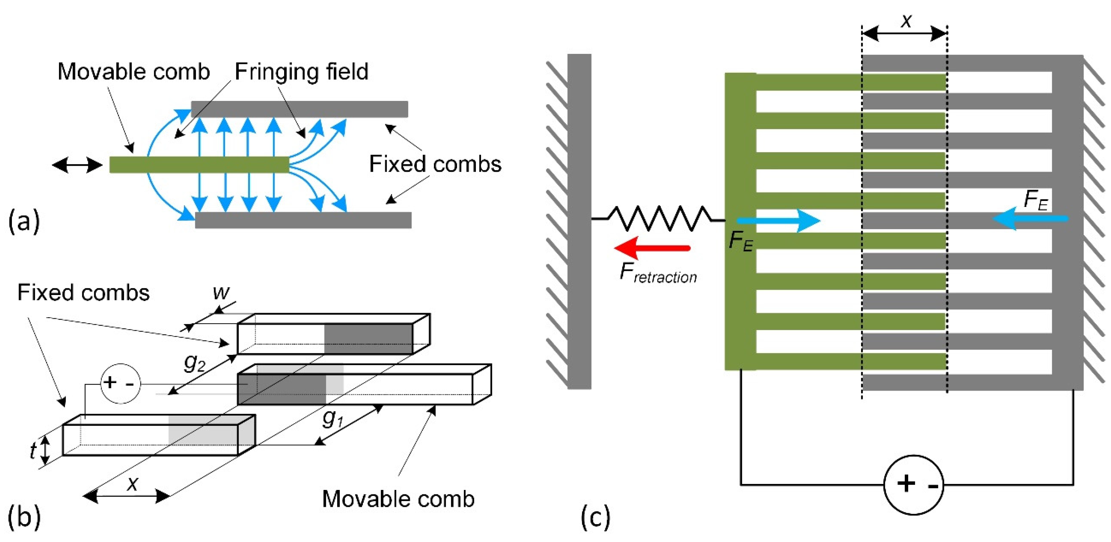
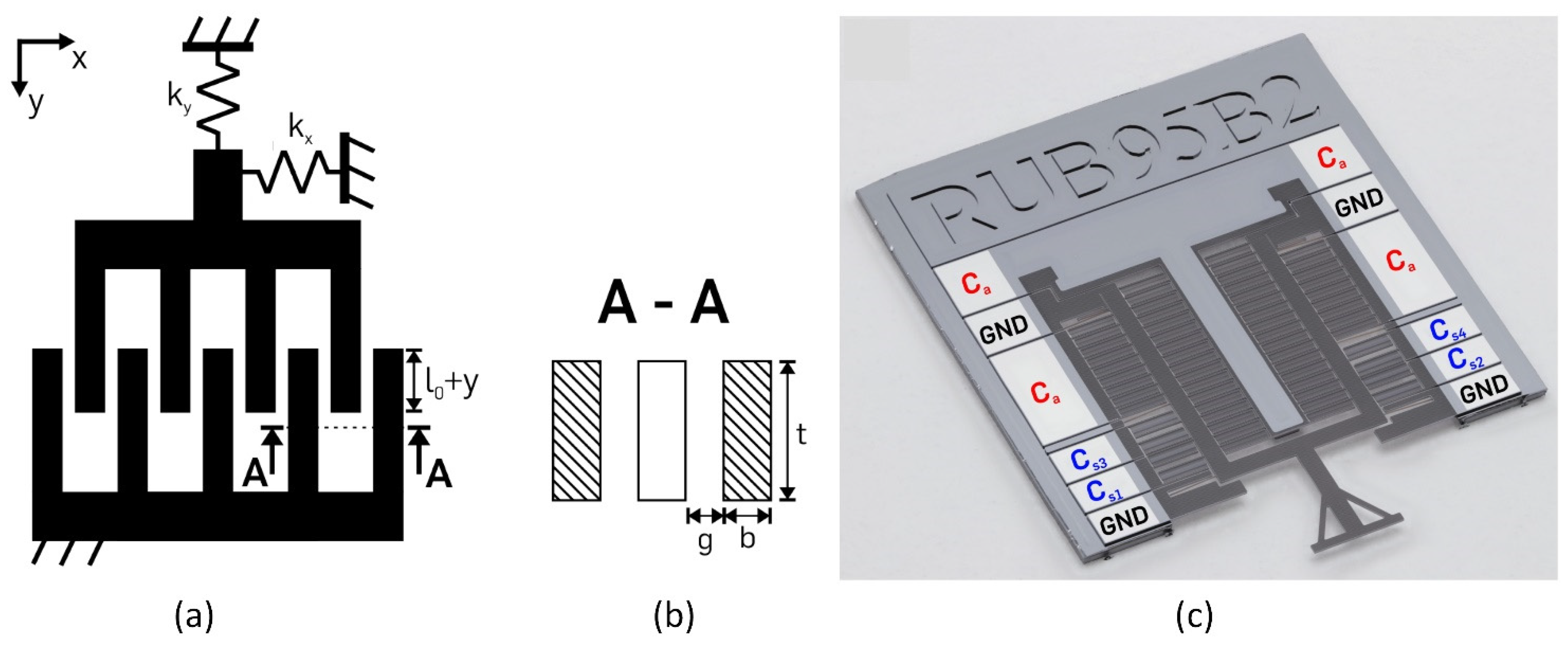
2.2. Comb-Drive Actuators

Comb-drive actuator design has movable and stationary structures, split in the fingers with the attached combs. Stationary parts are connected to a ground-fixed suspension (Figure 1). Coulomb forces deflect the moving comb structure and generate output displacement. Comb-drive electrostatic actuators can have a lateral and vertical design, which relates to the layout of the comb. Voltage-controlled comb-drive actuators are quite attractive in micro-positioning because of the lateral exposed electrostatic force independent of the position, contrary to the parallel-plate drives.
Figure 1. Comb-drive actuator: (a) operating principle, (b) geometry parameters, (c) acting forces. w—width, t—thickness, g1, g2—gaps between combs, x—overlapping length.
The biggest disadvantages of comb-drive actuators are moderate driving voltage, the small offset in direct current driving mode, and the large layout area [4]. Nevertheless, these disadvantages can be compensated by a higher displacement rate than other actuator types. A vertical comb-drive actuator is used to achieve greater angular movement. The design of a vertical actuator with a comb drive brings a higher deflection angle in low-voltage cases.
An electrostatic comb drive used in a moveable microsystem with non-linear springs [32] is presented in Figure 2. The device is dedicated to the manipulation of tissue samples and, simultaneously with the motion, can measure the displacement of the probe tip.
Figure 2. A single-sided electrostatic comb-drive actuator. (a) Schematic view, l0—finger overlap, y—displacement in y direction, kx, ky—spring stiffness in x and y directions; (b) a cross-section of the finger electrodes with finger gap g, width b, and depth t; (c) final processed constant-force microchip with electronic connections. Adapted from [32].
The variety of comb drives is typically distinguished by the different geometric parameters and various designs of output kinematic chains.
In the field of micro- and nanoactuators, comb drives are preferred rather than parallel drives due to their controllability and other characteristics. Comb structure allows increasing the surface area of the electrodes required to ensure sufficient output force. On the other hand, a comb drive requires more precise machining technologies, and the collapse effect still limits them.

2.3. Scratch-Drive Actuator

The scratch-drive actuator (SDA) was invented by Akiyama and Shono [33]. In this actuator, the structure is placed on the plate containing two bushings: moving and fixed. By applying voltage, the movable plate is pulled down to the substrate surface, and it creates a displacement of the unpowered part. When the voltage is removed, the unpowered drive returns back to the initial position.
Scratch-drive actuators fit MEMS technology and are especially useful for microoptoelectromechanical systems because they produce linear motion directly, have a potentially large travel range with a relatively large force, control the position and step size very well, and can also operate over a wide speed range [34].
MEMS actuators need higher voltages to generate large displacements; therefore, energy efficiency in the MEMS drives has lower values. Devices with electrostatic scratch actuators require less energy for higher force actuation but require power supplied by RF [35] or substrate [36] sources.
A full-gap tracking system was designed for parallel-plate electrostatic actuators [37]. The triboelectric generator was used for the operation of an electrostatic levitation self-powered normally closed MEMS switch [11]. The switch was opened by applying force to the generator.
Compared to comb- and parallel-plate drives, scratch actuators have a huge advantage—they do not suffer from the collapse effect. On the contrary, they use mechanical friction as a key effect for their operation. However, they have disadvantages too; the main of them is the requirement for a complex voltage pulse generator required for the precise control of the displacement or output force.

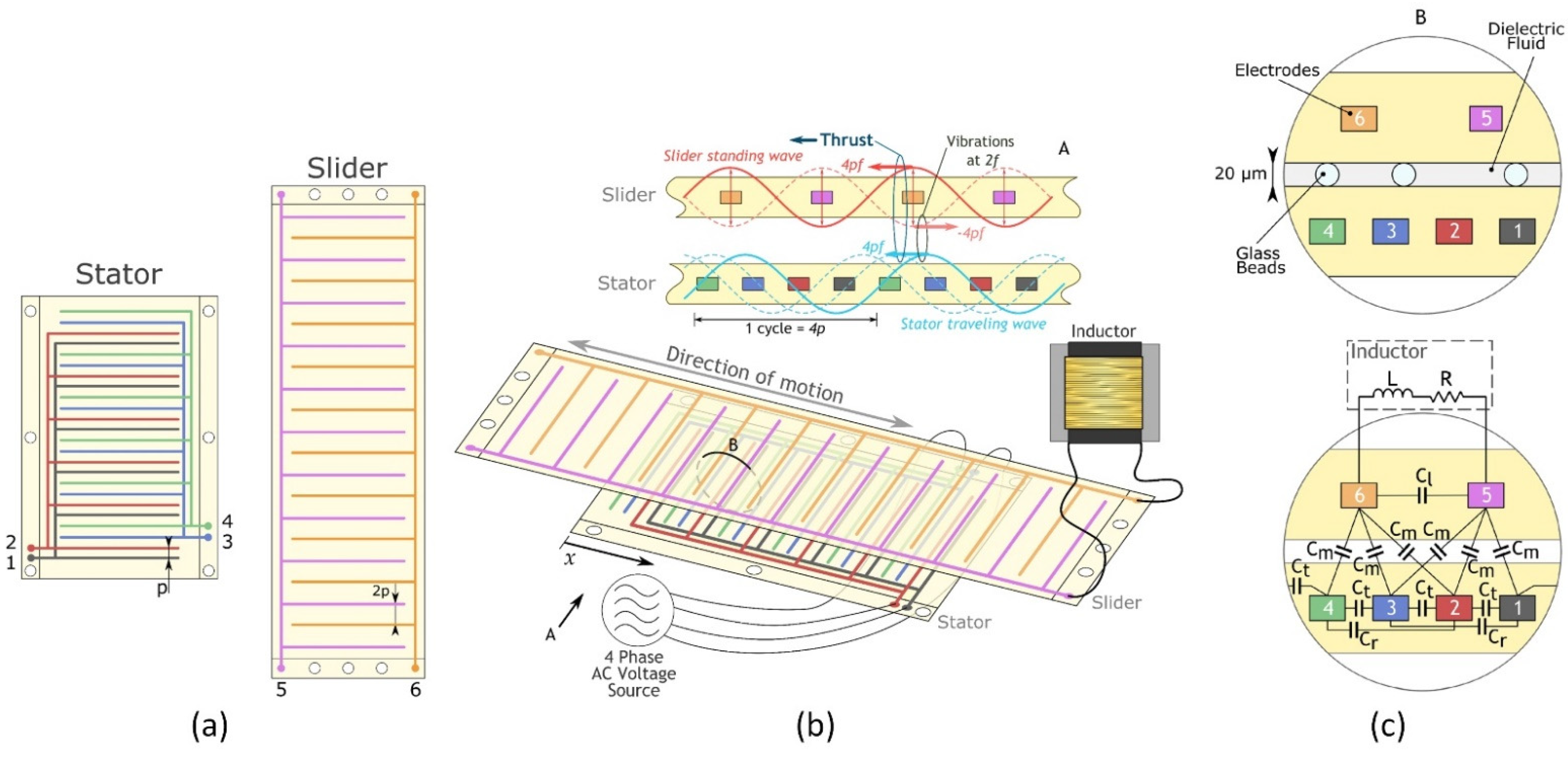
2.4. Rotary Actuators

In general, electrostatic rotary MEMS actuators have a simple design and are known for their high versatility, fast dynamic response, and low power consumption [38][39]. They can be divided into top-drive, side-drive, and wobble-drive actuators [39]. The highest rotor stability is achieved using the side-drive method; however, its torque is low. Large torque can be observed using the top-drive method, but then the stability of the rotor will be lower. Woo et al. proposed a three-phase 12-pole top-drive electrostatic rotary actuator with a ring-shaped bearing. It consists of stator and rotor electrodes, dielectric material, and a slip ring (bearing). The dielectric material helps to isolate the stator from the rotor and increases the capacitance.
The rotation movement of the microdrive simplifies the kinematic scheme in many applications, such as in the grippers, scrappers, or positioners. Rotary movement provides a possibility to improve movement resolution by changing object distance from the rotation axis and eliminating unnecessary gaps on sliders, which can provoke adhesion of some liquids or biological objects during live cell tests. On the other hand, distanced objects from the axis of rotation develop high torques; therefore, real drive size and power can overcome sliding mode ones. The limited range of angular movement is also a limitation of this drive design.
By summarizing the reported progress in developing the new design of electrostatic actuators in recent 5 years, it can be stated that the designs are the same. The main types are the parallel plate (sliding or bending), comb drive, scratch linear actuators, and their rotational versions.

3. Applications

The potential application of radiofrequency microelectromechanical (RF MEMS) switches can be used in various sensors, amplifiers, resonators, and phase converters [40]. Another prospective application of electrostatic actuators was presented in the work of Chen et al.: a bionic flapping-wing vehicle driven by a mechanical transmission structure and electrical motor [41]. The combination of elastomer and electrostatic actuators has been applied in the tactile display, which is characterized by simple production, compactness, and the ability to work at a wide range of frequencies (0.1–300 Hz) [42]. In the near future, such a device has the possibility to be applied in virtual-reality applications.
A resonant electrostatic induction micromotor with two to four phases was reported in [43]. It consists of two polymeric films with evenly spaced parallel copper electrodes. The slider film contains two phases, while the stator comprises four phases, as is shown in Figure 3. Due to the different number of phases, the slider and stator have a different pitch between electrodes but the same length of electrode cycles. Consequently, it creates interacting voltage waves generating the tangential electrostatic force between stator and slider. In such a configuration, the motor output force is proportional to the product of stator and slider voltages.
Figure 3. Schematic images of the 2–4-phase resonant electrostatic induction motor: (a) the general layout of the films, p—pitch for the stator electrode, 2p—pitch for the slider electrode; (b) their typical arrangement, external circuit components, and working principle; and (c) a more detailed section view with identification of the discrete capacitive elements. Adapted from [43].
Albukhari and Mescheder presented an actuation unit cell (AUC) [44]. The authors created a device capable of large actuation displacements (tens of mm) and forces (tens of N). Such unit cells could be suitable for bone distraction in osteogenesis cases to use as implantable actuators. The design of the system is shown in Figure 4. Pairs of AUCs are implemented in inchworm motors at both sides of two connected sliding shafts (Figure 2a). This device can be used in a cooperative microactuator system (Figure 4b).Micromachines 13 01256 g016 550
Figure 4. Inchworm motor: (a) concept; (b) the proposed AUC for the cooperative microactuator system, h—unit cell height, ww—width of the cell wall, s—stroke, V0—actuation voltage, ws—stopper width, le—stationary electrodes length, ls,y—spam beam length of y-axis spring, le,y—extension beam length of y-axis spring, lc,y—connector beam length of y-axis spring, le,x—extension beam length of x-axis spring, lc,x—connector beam length of x-axis spring. Adapted from [44].
Figure 5 shows a schematic of the switch (a) and a cross-sectional view (b) [37]. The electrodes come into contact at a switching voltage between the left and center electrodes. The radio frequency (RF) signal goes from the input port to the output port. The center and right electrodes come into contact, and the RF signal goes to the ground in the off state [45]. Part (c) of the figure shows an equivalent circuit. A central electrode is connected to the RF input port, and a left electrode is connected to the RF output port. The shunt switch consists of a central electrode, a right electrode connected to the ground, and an RF input port. Despite the gap between the electrodes of the serial switch, the connection to the ground provides high insulation to reverse in the off state. At a low actuation voltage, the gap makes the response time shorter. This actuator is efficient at an inrush voltage of less than 10 V and responds faster than 10 µs.
Figure 5. RF-MEMS switch with side movable triple electrodes actuator. (a) Overview; (b) cross-sectional view between A to A’; (c) an equivalent circuit [45].
Another MEMS switch based on an aluminum beam suspended by the torsion springs over the electrodes was presented in [46]. This switch has a low (4.9 V) pull-in voltage, but contrary to the typical switches, it is equipped with an active opening mechanism allowing recovery in a case of stiction.
The scanner based on comb actuators with a gimbaled frame as well as an outer (slow) and inner (fast) non-resonant and resonant axes is shown in Figure 6. A distributed spring is used to reduce dynamic deformation. The mirror diaphragm is 4 mm larger than most electrostatic devices, which limits the improvement of other parameters.
Figure 6. Scheme of the scanner: (a) layout of the scanner; (b) picture of the prototype. Adapted from [47].
Figure 7 shows the electrostatic principle of the shutter blade. In part (a) of the figure, the attachment of the shutter blade to the cover plate at a positive angle to the horizontal axis is depicted. Another analytical model is shown in part (b) of the figure when the torsion blade is retracted into the hole.
Figure 7. Side view of the three-port electrostatic mechanism. (a) The shutter blade locked upward for closing the aperture; (b) for opening the aperture, the shutter blade is retracted inward. Adapted from [48].
In the new model scanner system, the MEMS-based pull-and-push drive is fully integrated with the micro-made waveguide, which increases the robustness (Figure 8). The device is designed to work in tight spaces, as the integrated actuator reduces rigid length as well as the integrated light source and the scanner probe into one package. The MEMS-based push–pull actuator provides a better noise-to-signal ratio and relatively less power consumption during operation compared to commercially available actuators. The push-and-pull actuator mechanism can provide 2D scanning motion via 1D actuation.
Figure 8. Electrostatic MEMS scanner: (a) scheme; (b) prototype. Adapted from [49].
Flexible hydraulically reinforced electrostatic actuators less than mm thick were described in [50]. Such an actuator consists of a liquid-filled cavity, the shell of which is made from an elastomer and a metalized polyester. Applying voltage to the electrodes creates a zipping motion by pushing the fluid into the center of tension and forming a raised bump. This type of actuator is able to move both out off-plane and in-plane.
The application area of electrostatic actuators is quite big. RF-MEMS actuators have the largest application area; they are used in satellite vehicles, sensors, amplifiers, resonators, and phase converters. Inchworm motors and electrostatic induction micromotors designed by the electrostatic actuation principle are good candidates for moving microparticles. The fast-growing technology of microrobots requires new small high-performance actuators with low actuation voltage. Electrostatic microactuators can fill this gap successfully.

References

  1. Ozdogan, M.; Daeichin, M.; Ramini, A.; Towfighian, S. Parametric resonance of a repulsive force MEMS electrostatic mirror. Sens. Actuators A Phys. 2017, 265, 20–31.
  2. Rosa, M.A.; De Bruyker, D.; Völkel, A.R.; Peeters, E.; Dunec, J. A novel external electrode configuration for the electrostatic actuation of MEMS based devices. J. Micromech. Microeng. 2004, 14, 446.
  3. Qiao, D.-Y.; Yuan, W.-Z.; Li, X.-Y. A two-beam method for extending the working range of electrostatic parallel-plate micro-actuators. J. Electrost. 2007, 65, 256–262.
  4. Chiou, J.C.; Lin, Y.J. A novel large displacement electrostatic actuator: Pre-stress comb-drive actuator. J. Micromech. Microeng. 2005, 15, 1641.
  5. Schaler, E.W.; Zohdi, T.I.; Fearing, R.S. Thin-film repulsive-force electrostatic actuators. Sens. Actuators A Phys. 2018, 270, 252–261.
  6. Zamanzadeh, M.; Azizi, S. Static and dynamic characterization of micro-electro-mechanical system repulsive force actuators. J. Vib. Control 2020, 26, 1216–1231.
  7. Schaler, E.W.; Jiang, L.; Lee, C.; Fearing, R.S. Bidirectional, Thin-Film Repulsive-/Attractive-Force Electrostatic Actuators for a Crawling Milli-Robot. In Proceedings of the MARSS 2018—International Conference on Manipulation, Automation and Robotics at Small Scales, Nagoya, Japan, 4–8 July 2018; Institute of Electrical and Electronics Engineers Inc.: New York City, NY, USA, 2018.
  8. Poletkin, K. On the static pull-in of tilting actuation in electromagnetically levitating hybrid micro-actuator: Theory and experiment. Actuators 2021, 10, 256.
  9. Poletkin, K.V.; Asadollahbaik, A.; Kampmann, R.; Korvink, J.G. Levitating micro-actuators: A review. Actuators 2018, 7, 17.
  10. Pallay, M.; Towfighian, S. A reliable MEMS switch using electrostatic levitation. Appl. Phys. Lett. 2018, 113, 213102.
  11. Pallay, M.; Ibrahim, A.I.; Miles, R.N.; Towfighian, S. Pairing electrostatic levitation with triboelectric transduction for high-performance self-powered MEMS sensors and actuators. Appl. Phys. Lett. 2019, 115, 133503.
  12. Pallay, M.; Towfighian, S. A Combined MEMS Threshold Pressure Sensor and Switch. In Proceedings of the 2019 IEEE Sensors, Montreal, QC, Canada, 27–30 October 2019.
  13. Pallay, M.; Miles, R.N.; Towfighian, S. Merging parallel-plate and levitation actuators to enable linearity and tunability in electrostatic MEMS. J. Appl. Phys. 2019, 126, 014501.
  14. Pallay, M.; Miles, R.N.; Towfighian, S. A Tunable Electrostatic MEMS Pressure Switch. IEEE Trans. Ind. Electron. 2020, 67, 9833–9840.
  15. Pallay, M.; Towfighian, S. Feasibility study of a capacitive MEMS filter using electrostatic levitation. In Proceedings of the International Design Engineering Technical Conferences and Computers and Information in Engineering Conference, Anaheim, CA, USA, 18–21 August 2019.
  16. Mousavi, M.; Alzgool, M.; Towfighian, S. Electrostatic levitation: An elegant method to control MEMS switching operation. Nonlinear Dyn. 2021, 104, 3139–3155.
  17. Mousavi, M.; Alzgool, M.; Towfighian, S. Autonomous shock sensing using bi-stable triboelectric generators and MEMS electrostatic levitation actuators. Smart Mater. Struct. 2021, 30, 065019.
  18. Pallay, M.; Miles, R.N.; Towfighian, S. Towards a high bias voltage MEMS filter using electrostatic levitation. Mech. Syst. Signal Process. 2021, 150, 107250.
  19. Ozdogan, M.; Towfighian, S.; Miles, R.N. Fabrication and Experimental Characterization of a MEMS Microphone Using Electrostatic Levitation. In Proceedings of the 2019 IEEE Sensors, Montreal, QC, Canada, 27–30 October 2019.
  20. Ozdogan, M.; Towfighian, S.; Miles, R.N. Modeling and Characterization of a Pull-in Free MEMS Microphone. IEEE Sens. J. 2020, 20, 6314–6323.
  21. Hasan, M.N.; Pallay, M.; Towfighian, S. Threshold Pressure Sensing Using Parametric Resonance in Electrostatic MEMS. In Proceedings of the 2019 IEEE Sensors, Montreal, QC, Canada, 27–30 October 2019; pp. 4–7.
  22. Zamanzadeh, M.; Jafarsadeghi-Pournaki, I.; Ouakad, H.M. A resonant pressure MEMS sensor based on levitation force excitation detection. Nonlinear Dyn. 2020, 100, 1105–1123.
  23. Poletkin, K. Static Pull-in Behavior of Hybrid Levitation Micro-Actuators: Simulation, Modelling and Experimental Study. IEEE/ASME Trans. Mechatron. 2020, 4435, 1–11.
  24. Mousavi, M.; Alzgool, M.; Towfighian, S. A MEMS Pressure Sensor Using Electrostatic Levitation. IEEE Sens. J. 2021, 21, 18601–18608.
  25. Mayberry, M.; Ludois, D.C.; Severson, E.L. Towards Electrostatic Levitation of Rotating Machines. In Proceedings of the 2020 IEEE Energy Conversion Congress and Exposition (ECCE), Detroit, MI, USA, 11–15 October 2020; pp. 270–277.
  26. Zamanzadeh, M.; Jafarsadeghi Pournaki, I.; Azizi, S. Bifurcation analysis of the levitation force MEMS actuators. Int. J. Mech. Sci. 2020, 178, 105614.
  27. Burugupally, S.P.; Perera, W.R. Dynamics of a parallel-plate electrostatic actuator in viscous dielectric media. Sens. Actuators A Phys. 2019, 295, 366–373.
  28. Admassu, D.; Durowade, T.; Velicu, S.; Sivananthan, S.; Gao, W. Estimation of the mechanical stiffness constant of MEMS-based parallel-plate micro-actuators. Microsyst. Technol. 2021, 27, 2751–2759.
  29. Sano, C.; Ataka, M.; Hashiguchi, G.; Toshiyoshi, H. An electret-augmented low-voltage MEMS electrostatic out-of-plane actuator for acoustic transducer applications. Micromachines 2020, 11, 267.
  30. Alcheikh, N.; Ramini, A.; Al Hafiz, M.A.; Younis, M.I. Tunable clamped-guided arch resonators using electrostatically induced axial loads. Micromachines 2017, 8, 14.
  31. Schmitt, L.; Hoffmann, M. Large stepwise discrete microsystem displacements based on electrostatic bending plate actuation. Actuators 2021, 10, 272.
  32. Thewes, A.C.; Schmitt, P.; Löhler, P.; Hoffmann, M. Design and characterization of an electrostatic constant-force actuator based on a non-linear spring system. Actuators 2021, 10, 192.
  33. Akiyama, T.; Shono, K. Controlled Stepwise Motion in Polysilicon Microstructures. J. Microelectromech. Syst. 1993, 2, 106–110.
  34. Li, L.; Brown, J.G.; Uttamchandani, D. Study of scratch drive actuator force characteristics. J. Micromech. Microeng. 2002, 12, 736–741.
  35. Basset, P.; Kaiser, A.; Bigotte, P.; Collard, D.; Buchaillot, L. A large stepwise motion electrostatic actuator for a wireless microrobot. In Proceedings of the Fifteenth IEEE International Conference on Micro Electro Mechanical Systems, Las Vegas, NV, USA, 24 January 2002; pp. 606–609.
  36. Donald, B.R.; Levey, C.G.; McGray, C.G.; Paprotny, I.; Rus, D. An untethered, electrostatic, globally controllable MEMS micro-robot. J. Microelectromech. Syst. 2006, 15, 1–15.
  37. Esteves Moreira, E.; Lima, V.; Serra Alves, F.; Cabral, J.; Gaspar, J.; Rocha, L.A. Full-gap tracking system for parallel plate electrostatic actuators using closed-loop control. Sens. Actuators A Phys. 2016, 244, 174–183.
  38. Veroli, A.; Buzzin, A.; Frezza, F.; de Cesare, G.; Hamidullah, M.; Giovine, E.; Verotti, M.; Belfiore, N.P. An approach to the extreme miniaturization of rotary comb drives. Actuators 2018, 7, 70.
  39. Woo, J.; Hahn, B.; Ahn, C. Position estimator design for a mems top-drive electrostatic rotary actuator. Sensors 2020, 20, 7081.
  40. Kurmendra; Kumar, R. A review on RF micro-electro-mechanical-systems (MEMS) switch for radio frequency applications. Microsyst. Technol. 2021, 27, 2525–2542.
  41. Chen, C.; Zhang, T. A review of design and fabrication of the bionic flapping wing micro air vehicles. Micromachines 2019, 10, 144.
  42. Phung, H.; Nguyen, C.T.; Jung, H.; Nguyen, T.D.; Choi, H.R. Bidirectional tactile display driven by electrostatic dielectric elastomer actuator. Smart Mater. Struct. 2020, 29, 035007.
  43. Carneiro, F.; Zhang, G.; Osada, M.; Yoshimoto, S.; Yamamoto, A. An Extended Model for Ripple Analysis of 2–4 Phase Resonant Electrostatic Induction Motors. Actuators 2021, 10, 291.
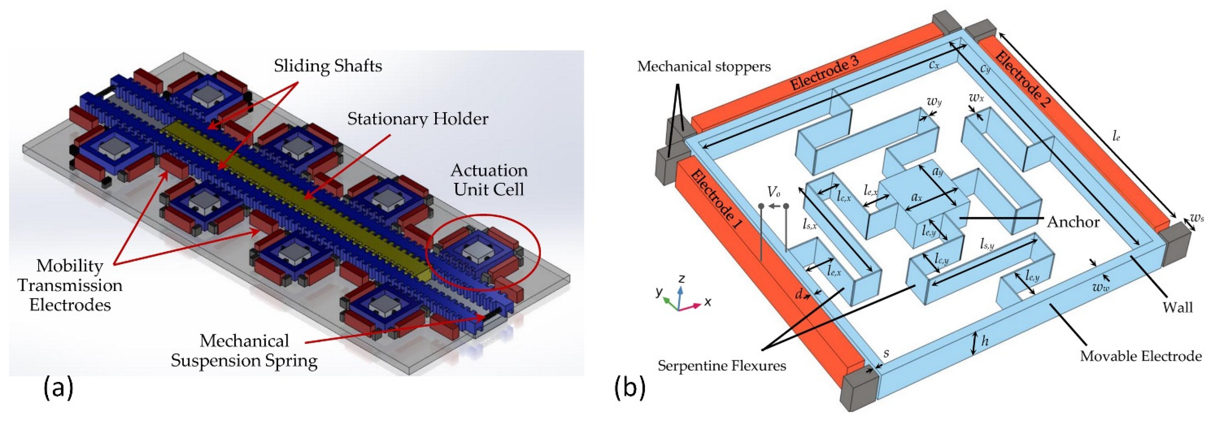
  44. Albukhari, A.; Mescheder, U. Investigation of the dynamics of a 2-DoF actuation unit cell for a cooperative electrostatic actuation system. Actuators 2021, 10, 276.
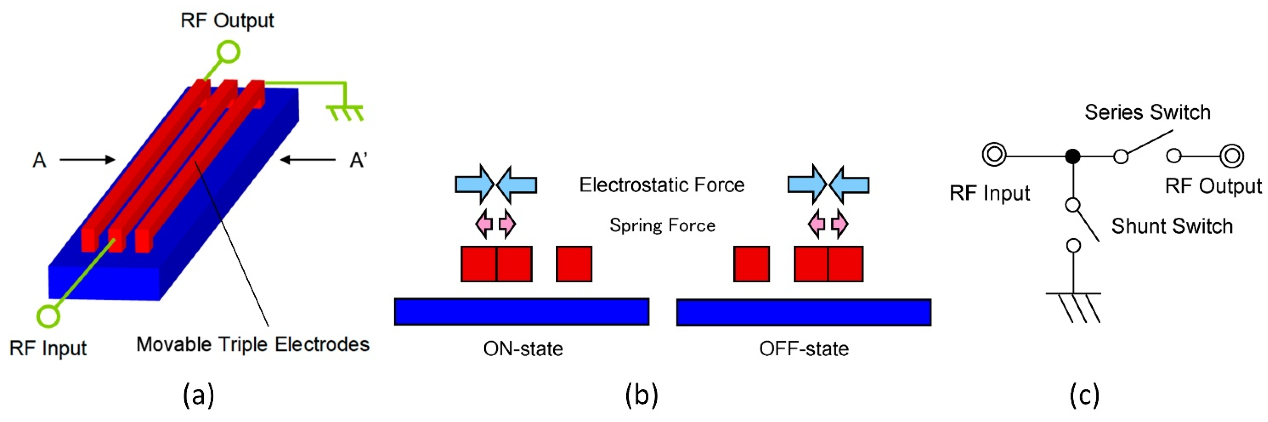
  45. Naito, Y.; Nakamura, K.; Uenishi, K. Laterally movable triple electrodes actuator toward low voltage and fast response RF-MEMS switches. Sensors 2019, 19, 864.
  46. Uvarov, I.V.; Kupriyanov, A.N. Stiction-protected MEMS switch with low actuation voltage. Microsyst. Technol. 2019, 25, 3243–3251.
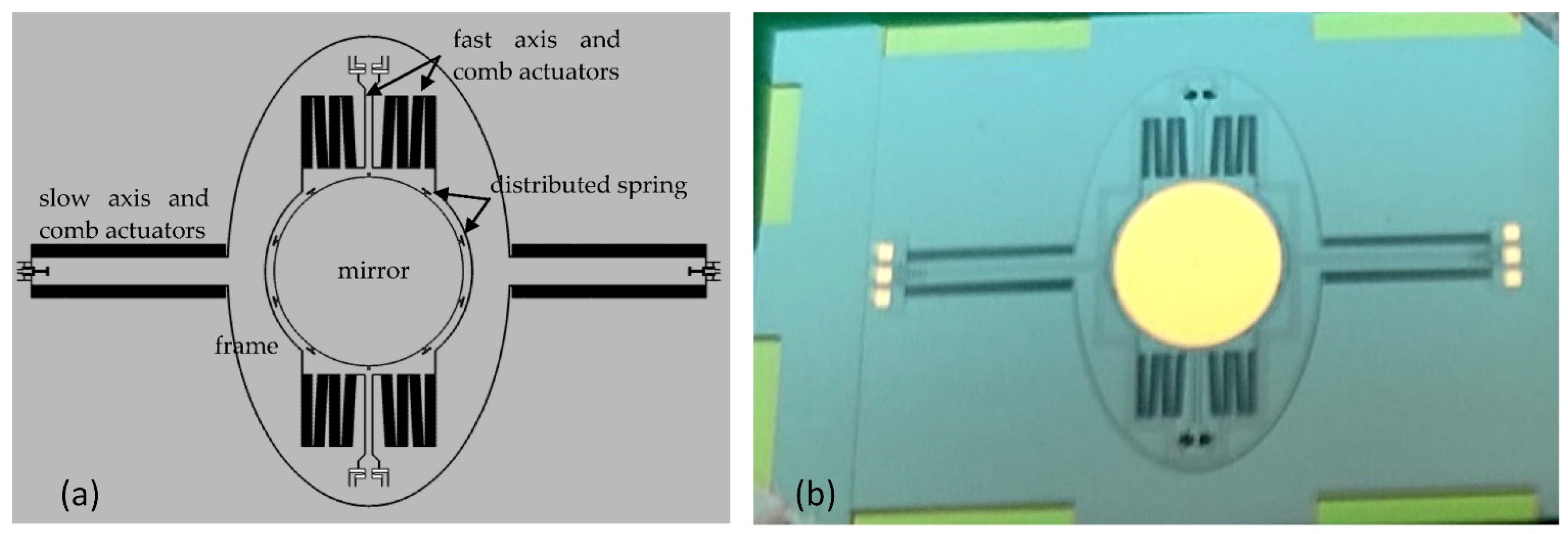
  47. Wang, Q.; Wang, W.; Zhuang, X.; Zhou, C.; Fan, B. Development of an electrostatic comb-driven mems scanning mirror for two-dimensional raster scanning. Micromachines 2021, 12, 378.
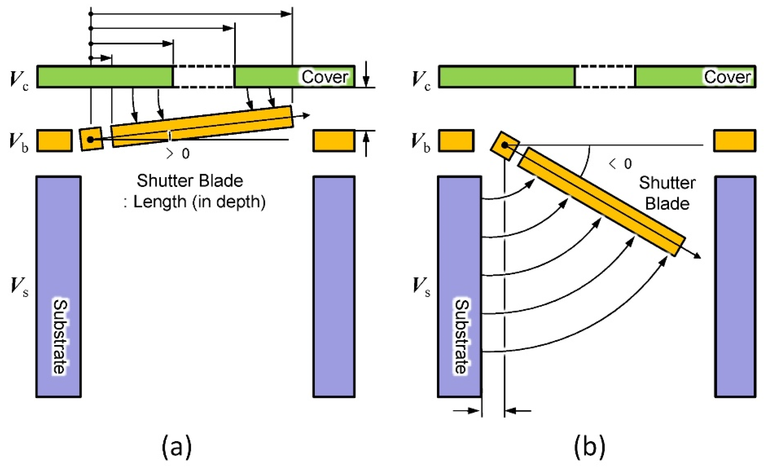
  48. Liu, X.; Takahashi, T.; Konishi, M.; Motohara, K.; Toshiyoshi, H. Random access addressing of MEMS electrostatic shutter array for multi-object astronomical spectroscopy. Micromachines 2020, 11, 782.
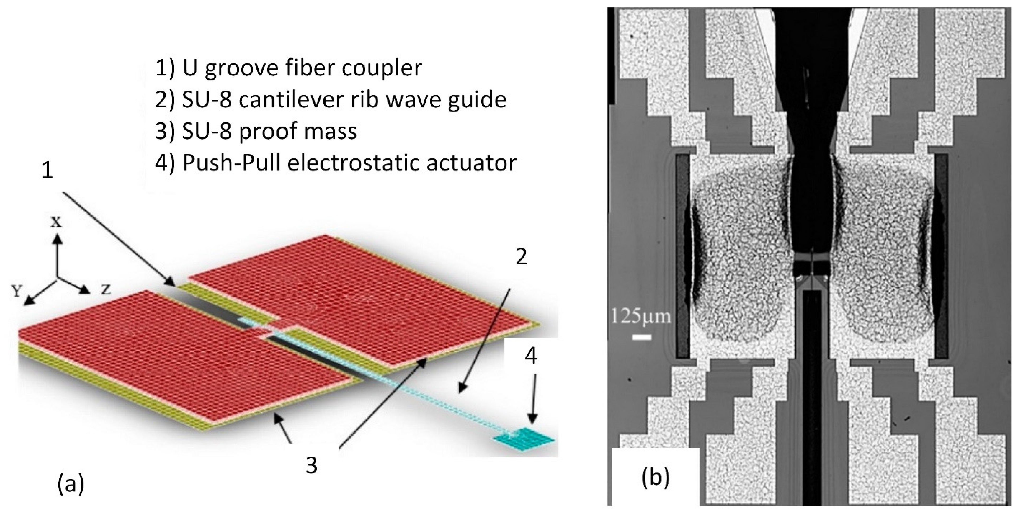
  49. Wang, W.C.; Gu, K.; Tsui, C.L. Design and fabrication of a push-pull electrostatic actuated cantilever waveguide scanner. Micromachines 2019, 10, 432.
  50. Leroy, E.; Hinchet, R.; Shea, H. Multimode Hydraulically Amplified Electrostatic Actuators for Wearable Haptics. Adv. Mater. 2020, 32, 2002564.
More
Information
Contributors MDPI registered users' name will be linked to their SciProfiles pages. To register with us, please refer to https://encyclopedia.pub/register : , , , , ,
View Times: 1.2K
Revisions: 3 times (View History)
Update Date: 26 Aug 2022
1000/1000
Video Production Service