
| Version | Summary | Created by | Modification | Content Size | Created at | Operation |
|---|---|---|---|---|---|---|
| 1 | Shahid Aziz Khan | -- | 3391 | 2022-07-14 17:58:33 | | | |
| 2 | Jessie Wu | -458 word(s) | 2933 | 2022-07-15 05:04:23 | | | | |
| 3 | Jessie Wu | + 67 word(s) | 3000 | 2022-07-15 05:16:05 | | | | |
| 4 | Jessie Wu | Meta information modification | 3000 | 2022-07-15 07:39:14 | | | | |
| 5 | Jessie Wu | Meta information modification | 3000 | 2022-07-15 07:43:12 | | | | |
| 6 | Jessie Wu | Meta information modification | 3000 | 2022-07-15 07:51:10 | | |
Video Upload Options
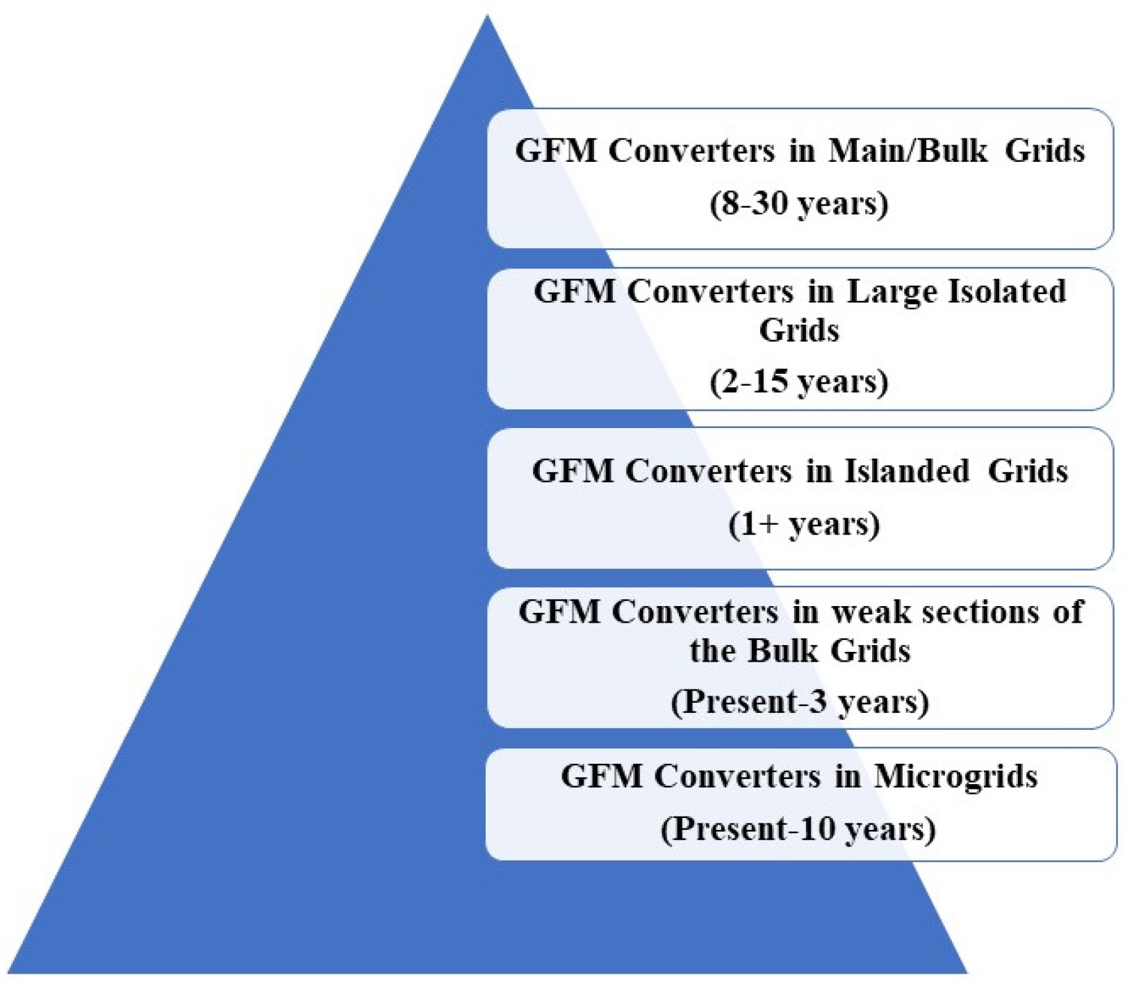
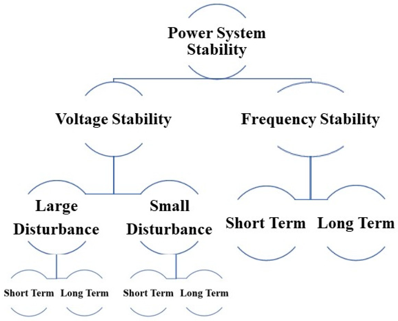
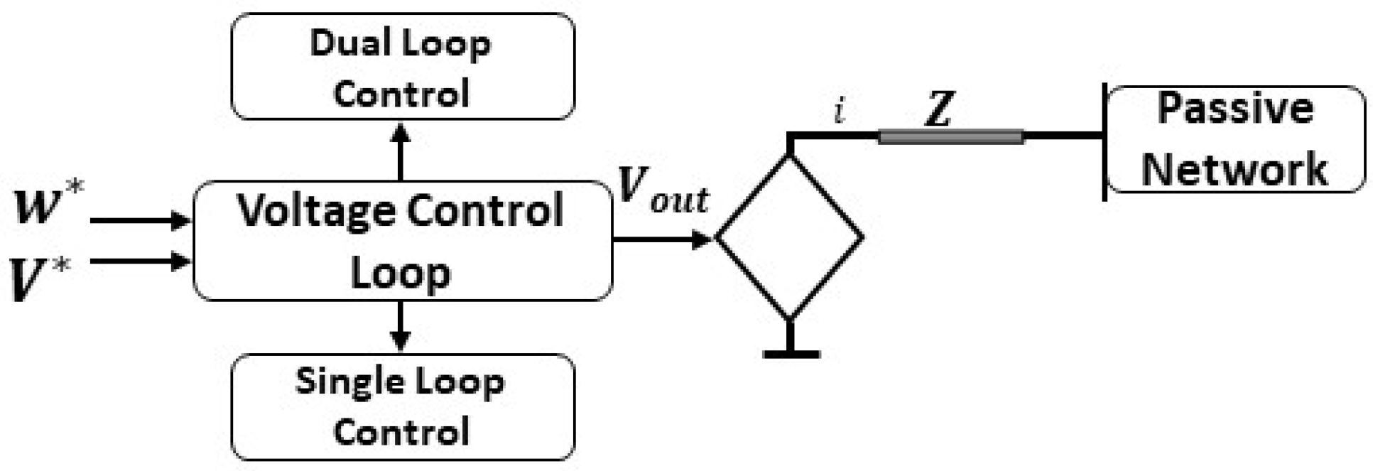
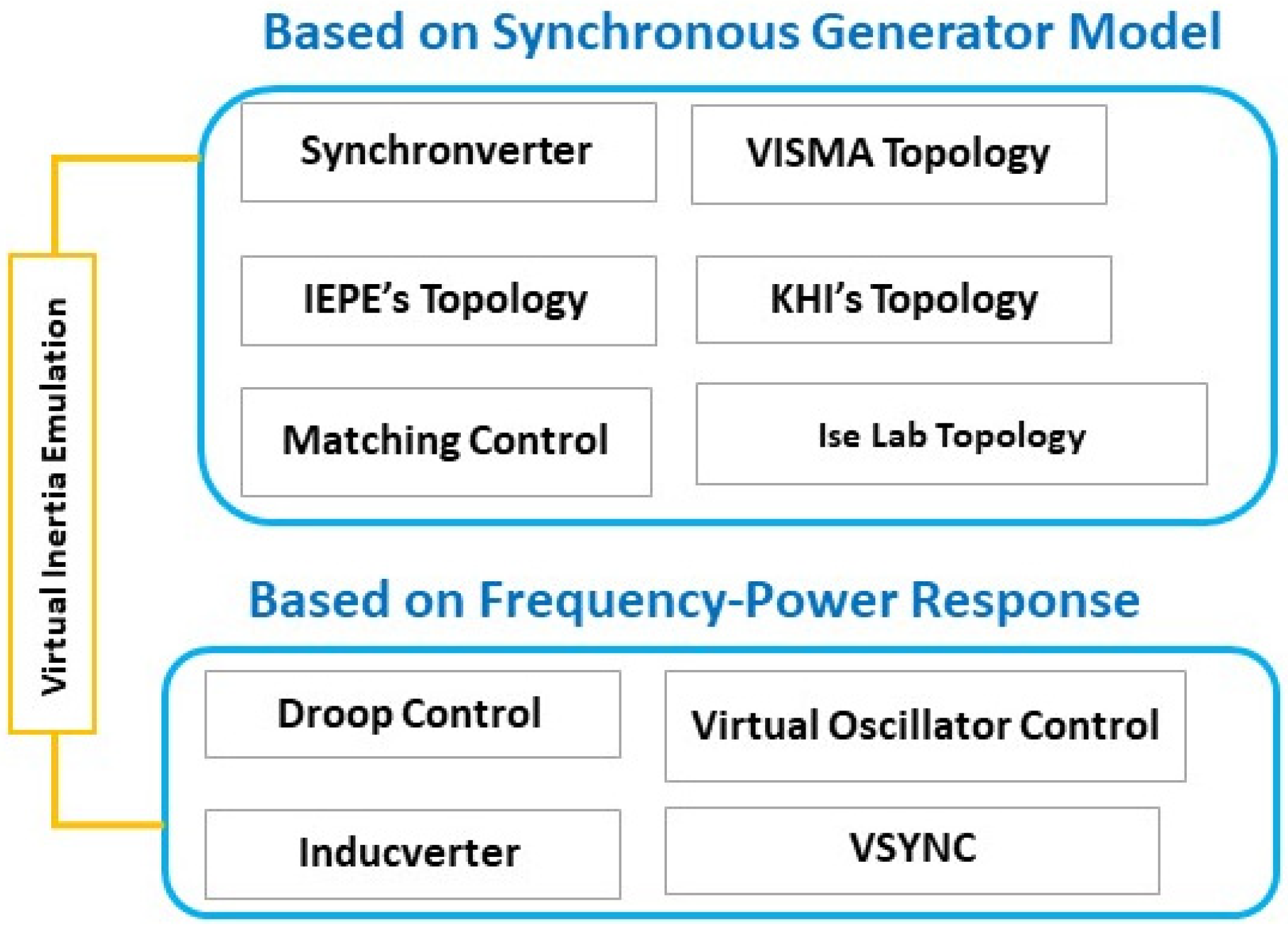
Historically, the power system has relied on synchronous generators (SGs) to provide inertia and maintain grid stability. However, because of the increased integration of power-electronics-interfaced renewable energy sources, the grid’s stability has been challenged in the last decade due to a lack of inertia. Currently, the system predominantly uses grid-following (GFL) converters, built on the assumption that inertial sources regulate the system stability. Such an assumption does not hold for the low-inertia grids of the future. Grid-forming (GFM) converters, which mimic the traditional synchronous machinery’s functionalities, have been identified as a potential solution to support the low-inertia grids. The performance analysis of GFM converters for small-signal instability can be found in the literature, but large-signal instability is still an open research question. Moreover, various topologies and configurations of GFM converters have been proposed. Still, no comparative study combining all GFC configurations from the perspective of large-signal stability issues can be found. This research combines and compares all the existing GFM control schemes from the perspective of large-signal stability issues to pave the way for future research and development of GFM converters for large-signal stability analysis and stabilization of the future low-inertia grids.
1. Introduction
2. Large-Signal Stability Issues
3. Frequency Stability

4. Voltage Stability
5. Grid-Forming Converters Topologies
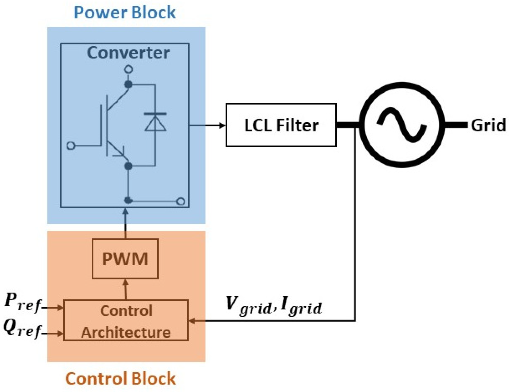
5.1. Synchronverter

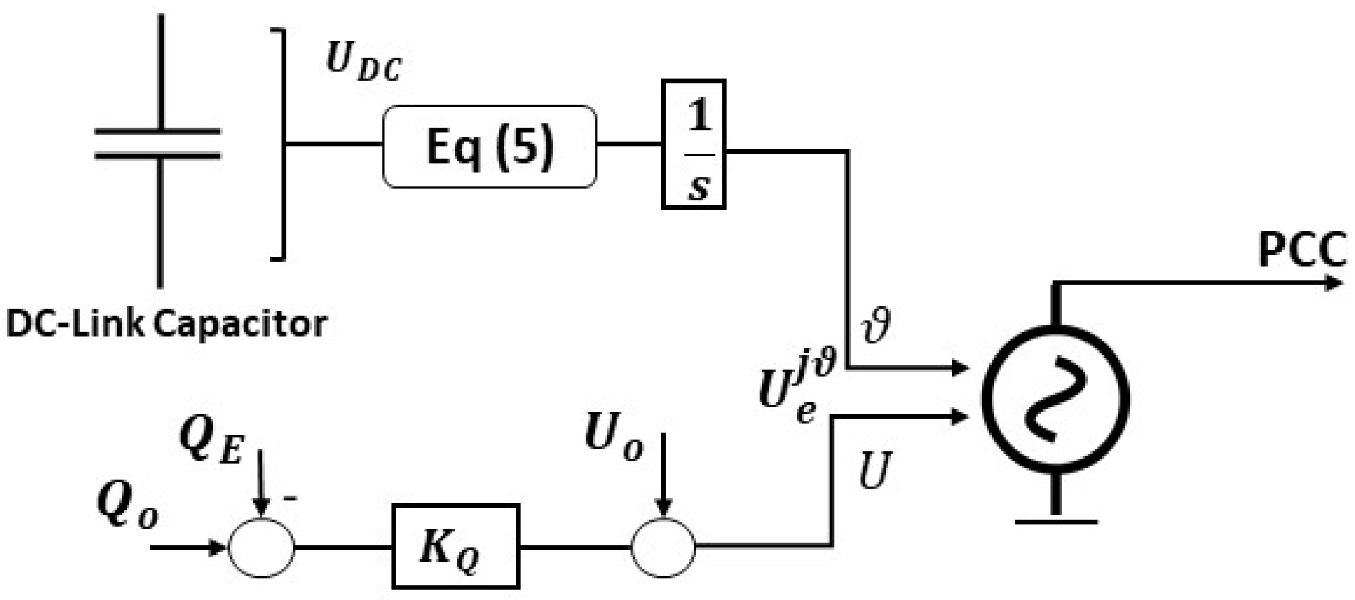
5.2. Matching Control
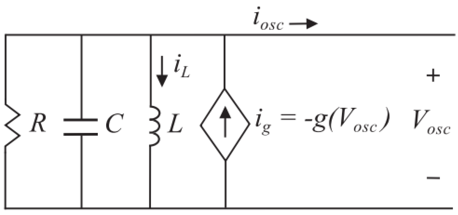
5.3. Virtual Oscillator Control (VOC)
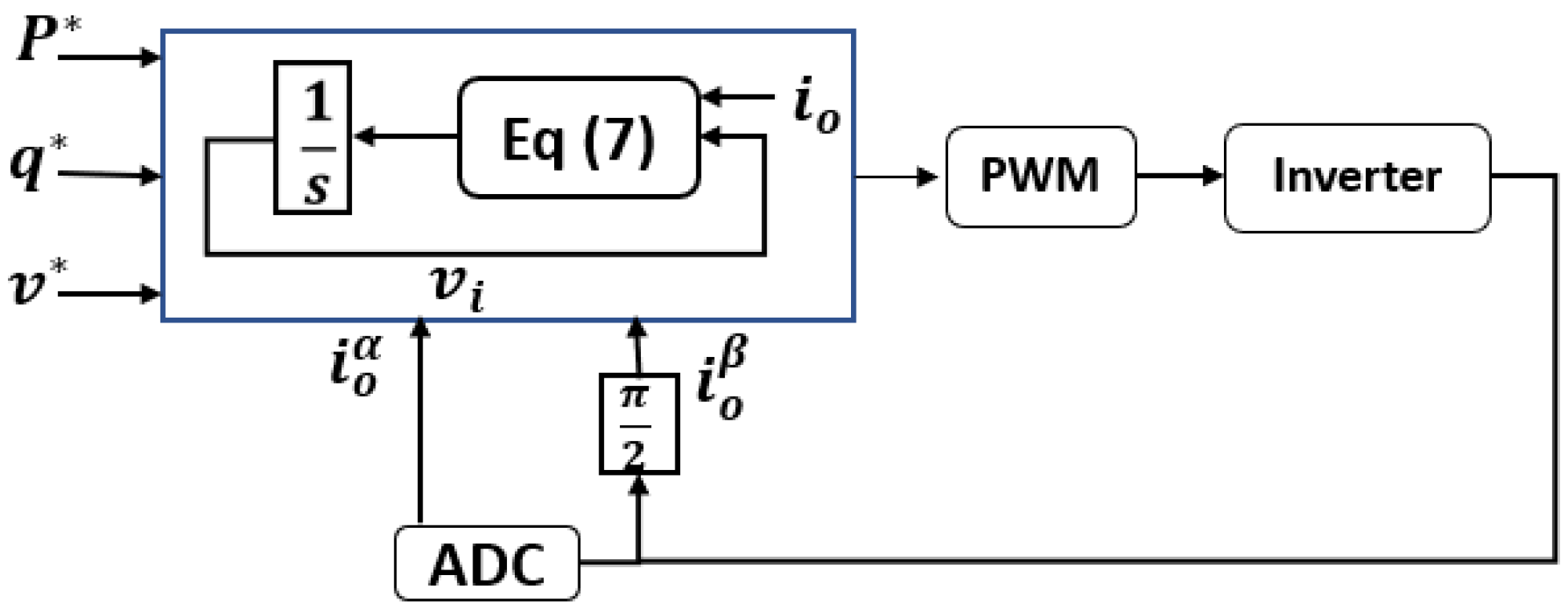
5.4. Dispatchable Virtual Oscillator (dVOC)
5.5. Direct Voltage (V-f) Control


References
- Bottrell, N.; Green, T.C. Comparison of current-limiting strategies during fault ride-through of inverters to prevent latch-up and wind-up. IEEE Trans. Power Electron. 2014, 29, 3786–3797.
- Hou, X.; Sun, Y.; Zhang, X.; Lu, J.; Wang, P.; Guerrero, J.M. Improvement of frequency regulation in VSG-based AC microgrid via adaptive virtual inertia. IEEE Trans. Power Electron. 2020, 35, 1589–1602.
- Sato, T.; Asharif, F.; Umemura, A.; Takahashi, R.; Tamura, J. Cooperative Virtual Inertia and Reactive Power Control of PMSG Wind Generator and Battery for Improving Transient Stability of Power System. In Proceedings of the 2020 IEEE International Conference on Power and Energy (PECon), Penang, Malaysia, 7–8 December 2020; pp. 101–106.
- Alegria, E.; Brown, T.; Minear, E.; Lasseter, R.H. CERTS Microgrid Demonstration with Large-Scale Energy Storage and Renewable Generation. IEEE Trans. Smart Grid 2014, 5, 937–943.
- Golestan, S.; Guerrero, J.M.; Vasquez, J.C. Three-Phase PLLs: A Review of Recent Advances. IEEE Trans. Power Electron. 2017, 32, 1894–1907.
- Guerrero, J.M.; Vasquez, J.C.; Matas, J.; De Vicuña, L.G.; Castilla, M. Hierarchical Control of Droop-Controlled AC and DC Microgrids A General Approach Toward Standardization. IEEE Trans. Ind. Electron. 2011, 58, 158–172.
- Huang, S.-H.; Schmall, J.; Conto, J.; Adams, J.; Zhang, Y.; Carter, C. Voltage control challenges on weak grids with high penetration of wind generation: Ercot experience. In Proceedings of the 2012 IEEE Power and Energy Society General Meeting, San Diego, CA, USA, 22–26 July 2012; IEEE: Piscataway, NJ, USA, 2012; pp. 1–7.
- IEEE Std 1204–1997; IEEE Guide for Planning DC Links Terminating at AC Locations Having Low Short-Circuit Capacities. IEEE: Piscataway, NJ, USA, 1997; pp. 1–216.
- North American Electric Reliability Corporation (NERC). Protection System Response to Power Swings; NERC System Protection and Control Subcommittee Report; NERC: Atlanta, GA, USA, 2013.
- Erickson, M.J.; Jahns, T.M.; Lasseter, R.H. Improved Power Control Bandwidth of Grid-Forming Sources in a CERTS Microgrid. In Proceedings of the 2012 IEEE Energy Conversion Congress and Exposition, Raleigh, NC, USA, 15–20 September 2012; Institute of Electrical and Electronics Engineers: Piscataway, NJ, USA, 2012; pp. 2366–2373.
- Hossain, M.; Pota, H.; Issa, W.; Hossain, M. Overview of ac microgrid controls with inverter-interfaced generations. Energies 2017, 10, 1300.
- NERC. Inverter-Based Resource Performance Guideline; NERC: Atlanta, GA, USA, 2018.
- Deng, Z.; Wang, H.; Qin, Y.; Zhang, J.; Zhu, C.; Cai, X. Matching-Control of Wind Power System Based on Current Source Converter. In Proceedings of the 10th Renewable Power Generation Conference (RPG 2021), Online, 14–15 October 2021; pp. 144–150.
- Zhong, Q.; Weiss, G. Synchronverters: Inverters That Mimic Synchronous Generators. IEEE Trans. Ind. Electron. 2011, 58, 1259–1267.
- Zhong, Q.; Nguyen, P.; Ma, Z.; Sheng, W. Self-Synchronized Synchronverters: Inverters without a Dedicated Synchronization Unit. IEEE Trans. Power Electron. 2014, 29, 617–630.
- Dhople, S.V.; Johnson, B.B.; Hamadeh, A.O. Virtual Oscillator Control for voltage source inverters. In Proceedings of the 2013 51st Annual Allerton Conference on Communication, Control, and Computing (Allerton), Monticello, IL, USA, 2–4 October 2013; pp. 1359–1363.
- Seo, G.-S.; Colombino, M.; Subotic, I.; Johnson, B.; Gross, D.; Dorfler, F. Dispatchable Virtual Oscillator Control for Decentralized Inverter-Dominated Power Systems: Analysis and Experiments. In Proceedings of the 2019 IEEE Applied Power Electronics Conference and Exposition (APEC), Anaheim, CA, USA, 17–21 March 2019; National Renewable Energy Laboratory: Golden, CO, USA, 2019.
- Tayyebi, A.; Dörfler, F.; Kupzog, F.; Miletic, Z.; Hribernik, W. Grid-forming converters—Inevitability, control strategies and challenges in future grid applications. In Proceedings of the Workshop on Microgrids and Local Energy Communities (CIRED 2018), Ljubljana, Slovenia, 7–8 June 2018.
- Kim, J.; Guerrero, J.M.; Rodriguez, P.; Teodorescu, R.; Nam, K. Mode Adaptive Droop Control With Virtual Output Impedances for an Inverter-Based Flexible AC Microgrid. IEEE Trans. Power Electron. 2011, 26, 689–701.
- Hesse, R.; Turschner, D.; Beck, H. Micro grid stabilization using the virtual synchronous machine (VISMA). Renew. Energy Power Qual. J. 2009, 1, 676–681.
- Chen, Y.; Hesse, R.; Turschner, D.; Beck, H. Dynamic properties of the virtual synchronous machine (VISMA). Renew. Energy Power Qual. J. 2011, 11, 755–759.
- Chen, Y.; Hesse, R.; Turschner, D.; Beck, H. Comparison of methods for implementing virtual synchronous machine on inverters. In Proceedings of the International Conference on Renewable Energies and Power Quality (ICREPQ’12), Santiago de Compostela, Spain, 28–30 March 2012; pp. 734–739.
- Hirase, Y.; Abe, K.; Sugimoto, K.; Shindo, Y. A grid connected inverter with virtual synchronous generator684 model of algebraic type. IEEE Trans. Power Energy 2012, 132, 371–380.
- Li, M.; Huang, W.; Tai, N.; Duan, D. Virtual Inertia Control of the Virtual Synchronous Generator: A Review. arXiv 2021, arXiv:2109.07590.
- Liu, J.; Miura, Y.; Ise, T. Dynamic characteristics and stability comparisons between virtual synchronous generator and droop control in inverter-based distributed generators. In Proceedings of the 2014 International Power Electronics Conference (IPEC—Hiroshima 2014—ECCE ASIA), Hiroshima, Japan, 18–21 May 2014; pp. 1536–1543.
- Ashabani, M.; Freijedo, F.D.; Golestan, S.; Guerrero, J.M. Inducverters: PLL-Less Converters with Auto-Synchronization and Emulated Inertia Capability. IEEE Trans. Smart Grid 2016, 7, 1660–1674.
- Driesen, J.; Visscher, K. Virtual synchronous generators. In Proceedings of the 2008 IEEE Power and Energy Society General Meeting—Conversion and Delivery of Electrical Energy in the 21st Century, Pittsburgh, PA, USA, 20–24 July 2008; pp. 1–3.
- Morren, J.; Pierik, J.; de Haan, S.W.H. Inertial response of variable speed wind turbines. Electr. Power Syst. Res. 2006, 76, 980–987.
- Günther, K.; Sourkounis, C. Investigation of Virtual Synchronous Machine Control for the Grid-Side Converter of Wind Turbines with Permanently Excited Synchronous Generator. In Proceedings of the IECON 2019—45th Annual Conference of the IEEE Industrial Electronics Society, Lisbon, Portugal, 14–17 October 2019; pp. 2395–2401.
- Shang, L.; Hu, J.; Yuan, X.; Huang, Y. Improved virtual synchronous control for grid-connected VSCs under grid voltage unbalanced conditions. J. Mod. Power Syst. Clean Energy 2019, 7, 174–185.


