Grid-Forming Converters and Power System Stability: History
Please note this is an old version of this entry, which may differ significantly from the current revision.
Contributor: , , , ,

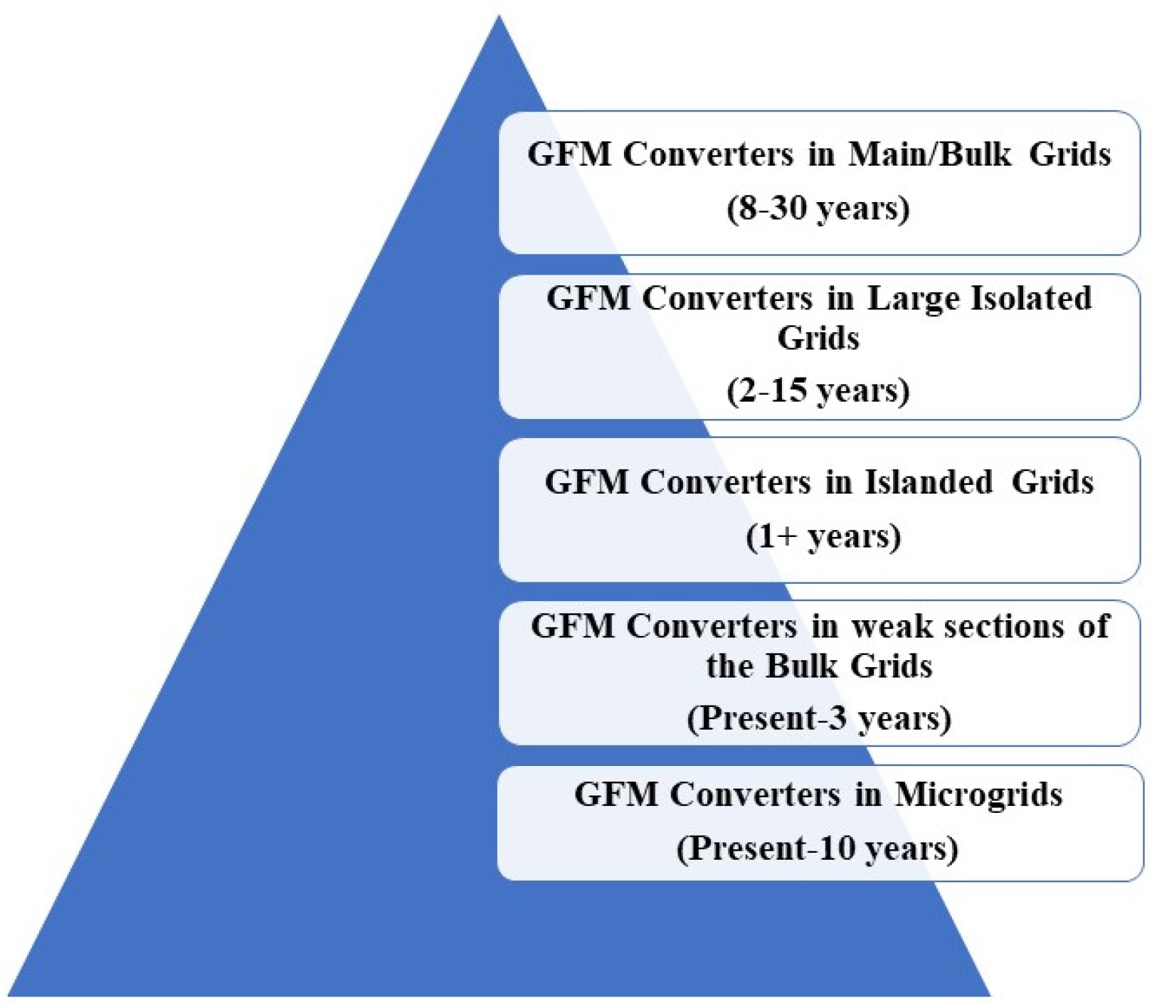
Historically, the power system has relied on synchronous generators (SGs) to provide inertia and maintain grid stability. However, because of the increased integration of power-electronics-interfaced renewable energy sources, the grid’s stability has been challenged in the last decade due to a lack of inertia. Currently, the system predominantly uses grid-following (GFL) converters, built on the assumption that inertial sources regulate the system stability. Such an assumption does not hold for the low-inertia grids of the future. Grid-forming (GFM) converters, which mimic the traditional synchronous machinery’s functionalities, have been identified as a potential solution to support the low-inertia grids. The performance analysis of GFM converters for small-signal instability can be found in the literature, but large-signal instability is still an open research question. Moreover, various topologies and configurations of GFM converters have been proposed. Still, no comparative study combining all GFC configurations from the perspective of large-signal stability issues can be found. This research combines and compares all the existing GFM control schemes from the perspective of large-signal stability issues to pave the way for future research and development of GFM converters for large-signal stability analysis and stabilization of the future low-inertia grids. 

  • grid-forming converters
  • renewable energy
  • stability

1. Introduction

Grid-forming (GFM) converters, a relatively new concept, cannot be readily implemented into the bulk grid system. Significant research and reliability tests for a more extended period are required before commissioning them into the bulk grids. Microgrids and island grids are a good starting point to mature and test the GFM technology. Figure 1 shows the grid-forming converters’ multi-year research and implementation road map [1].
Figure 1. Implementation road map of the GFM controls.
It is not wise and economically feasible to replace all existing predominantly GFL converters with grid-forming controls. The near-future power system will involve a mix of grid-following and grid-forming controls. The growth and performance of GFM converters over time will determine the speed of recognition as the penetration of RES increases. It also means that before reaching the goal of a 100% renewable energy-based grid, there will be a mixed/hybrid grid containing both traditional generators and power electronics-interfaced generation (RES). The power system stability can be analyzed and assessed through the system performance under frequency control, voltage control, and fault protection [2]Figure 2 provides the classification of the power system stability criteria.
Figure 2. Power system stability criteria.

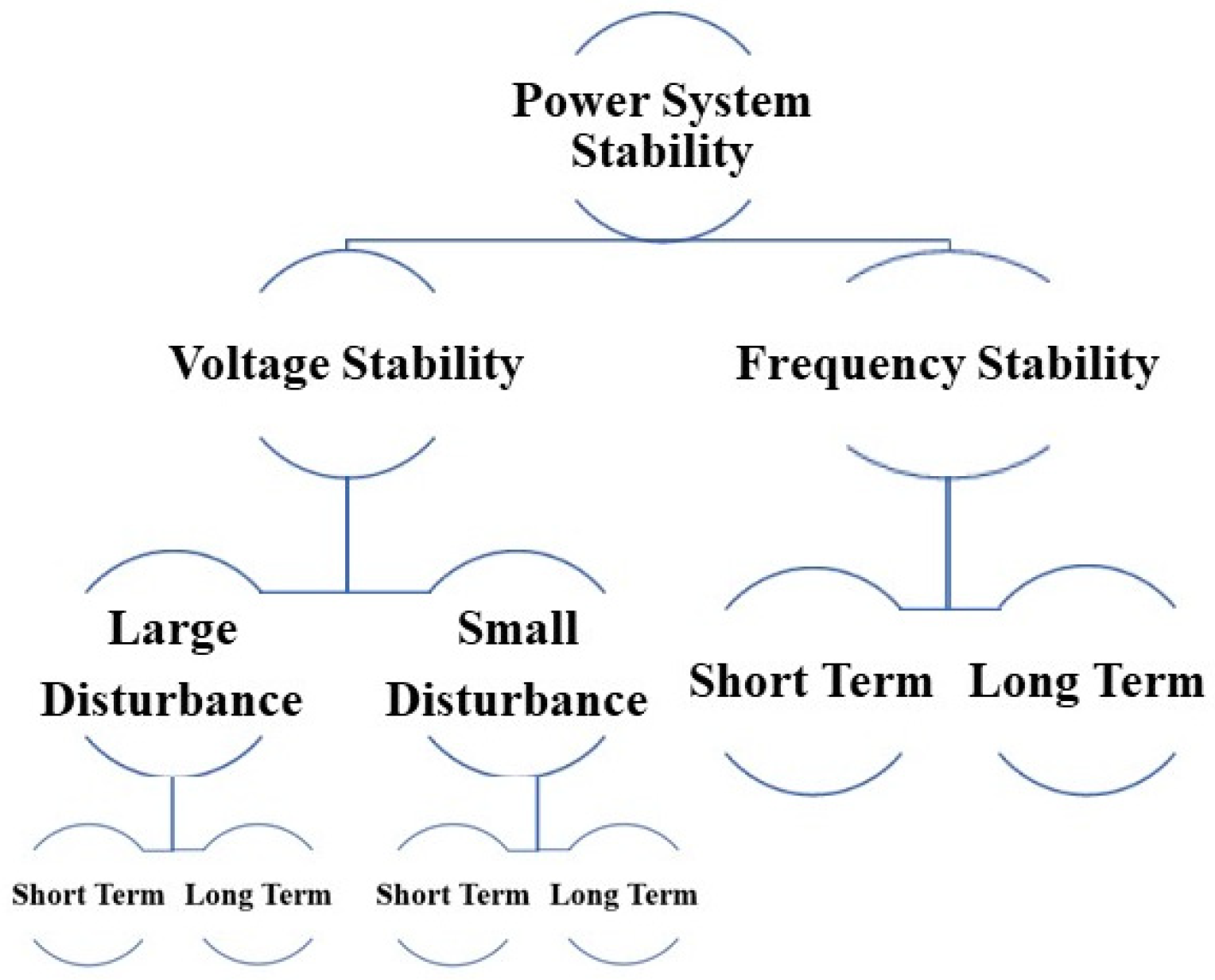
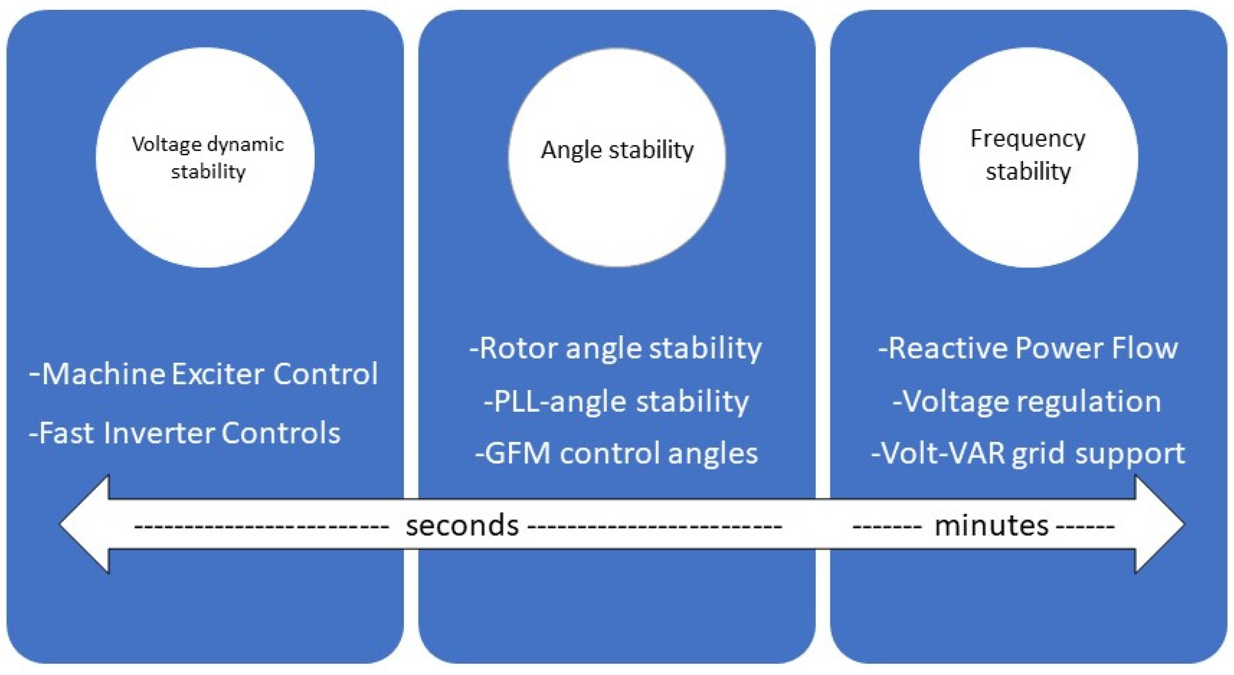
2. Large-Signal Stability Issues

In the case of a large-signal disturbance, such as a 3-phase AC fault, the GFM converter faces overcurrent problems; thus, current limiting strategies are necessary for safe operation. The two major fault-limiting strategies found in the literature include the instantaneous saturation limiter and latched limiter [3]. Due to the large-signal disturbance, the GFM converter’s operation mode switches from voltage source to current source mode. Both modes need exploration for the comprehensive analysis and understanding of large-signal stability.

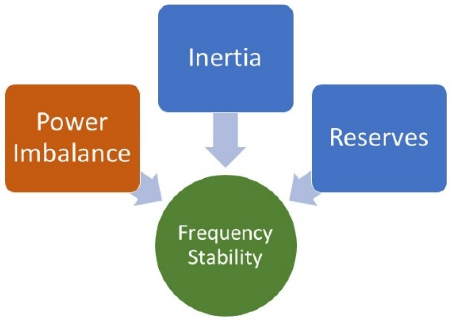
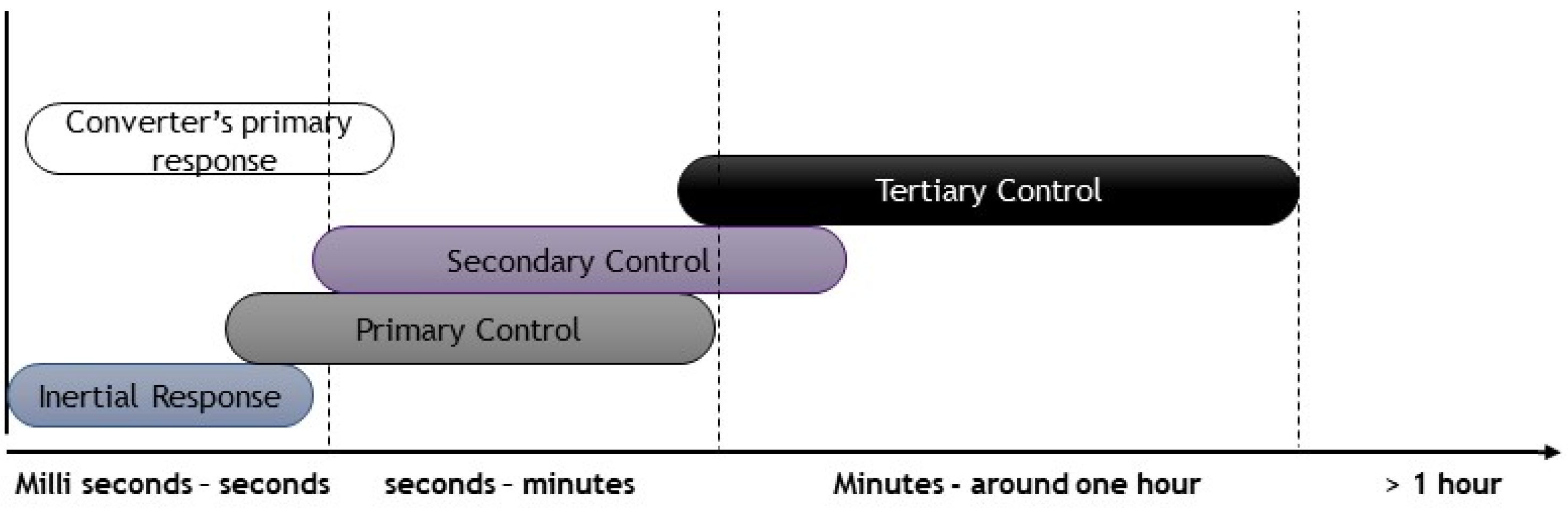
3. Frequency Stability

The frequency stability or control objective is to keep/regulate the frequency at the nominal or set value. The major indicators for monitoring and control are the rate of change of frequency (RoCoF) and frequency nadir. The contex of low-inertia grids leads to a higher RoCoF, and the frequency nadir falls outside the allowable limits. The addition of the rotational mass to the grid is directly proportional to the inertia emulation and increased damping. For converter-based renewable energy generation, the risk of high-frequency swings can be mitigated by GFM converter controls, which provide the inertial response and the primary frequency control by detecting the frequency swing and adjusting the power injection to maintain the nominal value [4]. Factors affecting the system stability are highlighted in Figure 3.
Figure 3. Factors affecting system stability.
To achieve a faster frequency control action after a large disturbance, a headroom or reserved capacity must be in place to mitigate the generation and the load imbalance. After disturbance, the frequency swing magnitude depends on the power imbalance. For inverter-interfaced sources, the reserve capacity can be obtained through inverter interfaced batteries or by operating the inverter at a value less than the rated value. The drawback is the unused capacity and the associated cost. It is to be noted that for large frequency deviations in low inertia, the primary control based on the spinning or mechanical reserves may not be fast enough [5]. So, fast-acting devices, such as converters, are the most suitable option for low-inertia grids. Figure 4 shows the control and response scheme associated with frequency dynamics and control. The rotation of the rotor provides the inertial response immediately for synchronous machines, while for a converter-dominated system, the inertial response is provided with a little bit of delay. After that, the primary, secondary, and tertiary controls take over. A faster primary frequency response than the conventional plants can be generated using power converters. Power converters, in general, have a fast response time. The challenge at hand is the inability of power converters to respond to natural power imbalances. This risk is in the first few milliseconds of the disturbance timescale. Due to the stochastic nature of RES, another challenge is ensuring and guaranteeing a given reserve and security.
Figure 4. Timescale frequency dynamics.
Multiple techniques can be realized considering frequency stability in the context of grid-forming controls. All GFM controls adhere to the p-f steady-state droop law through which the steady-state frequency deviations are controlled. Compared with the traditional grids, the established hierarchical control methods for inverter-interfaced microgrids are somewhat similar to the hierarchical control strategies. P-f droop slope can be used for each inverter’s primary response. The schemes having low bandwidth communication requirements have been used for secondary and tertiary response mechanisms [6][7]. These techniques used on droop inverters can be applied to the grid-forming inverters. The lack of matured and applied grid forming solutions holds back the hierarchical control strategies in microgrids and bulk systems. The steady-state response of all the GFM control methods is almost identical; however, their dynamic response is different.

4. Voltage Stability

Voltage stability can be understood as keeping the system voltage within the acceptable range. Dynamic voltage stability issues are experienced by the exisiting GFL converters in low-inertia grids. Recently, the case of voltage stability issues was reported by ERCOT, where the voltage at the 230 KV system dropped in a weak grid [8]. The principal reason behind such stability problems is the voltage reduction when the power order increases at the PCC. This coupling is due to the GFL control architecture aided by the weak inertial grid conditions. The short-circuit ratio (SCR) defines the grid strength, which is 1Xg, where Xg is the line reactance. If SCR < 3, it refers to a weak grid [9]. The system’s GFL control depends on the grid for voltage and frequency regulation. According to the NREL’s report on GFM converters, GFM converters are considered the only feasible and potential option that can provide frequency and voltage support services.
The voltage regulation or control action includes increasing or decreasing real and reactive power. Usually, GFM converters provide voltage control through reactive power due to its enhanced sensitivity, also known as the Q-V droop control. There is a tradeoff between steady-state voltage and reactive power for GFM converters. A common method used to balance the power control is known as volt–volt ampere reactive (VAR) control. Its functionality can be added to GFL inverters too. So, GFM converters can perform better and provide voltage support in weak inertial grids [10]. The importance of voltage control or stability is enhanced for the developing DC grids. Thus, there have been some advancements in voltage control in microgrids. In [11], virtual impedances have been added to reduce the parameter sensitivity and assist with the reactive power. Communication-based controllers offer low steady-state errors and great power-sharing capability [12]. These approaches apply only to systems where a communication link is possible and with high fault current magnitudes. As the future bulk grids and microgrids would be geographically distributed and the fault current of the GFM converters is not high, these approaches cannot be applied. Specific new approaches and stability criteria are required for the developing systems. Ref. [13] reported adverse effects and responses when GFM converters and synchronous machines were combined for the voltage regulation. Similar issues are also found with the mature GFL converter technology. Such uncertain responses are harmful to a hybrid grid network, and more research needs to be performed to find the root cause and a remedy for this problem. The stability framework includes only frequency, voltage, and rotor angle stability for the traditional power grids. Compared to the classical, the modern and future systems will include more controls and factors, as shown in Figure 5.
Figure 5. Futuristic power system stability framework.

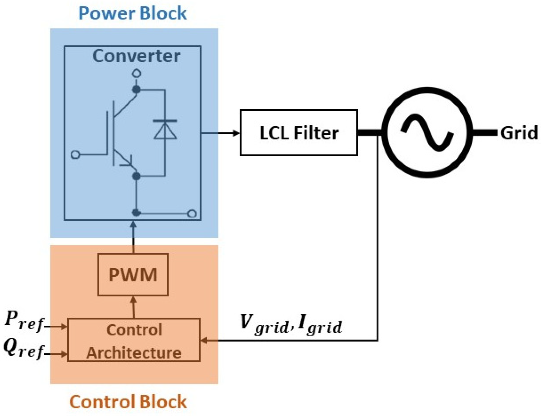
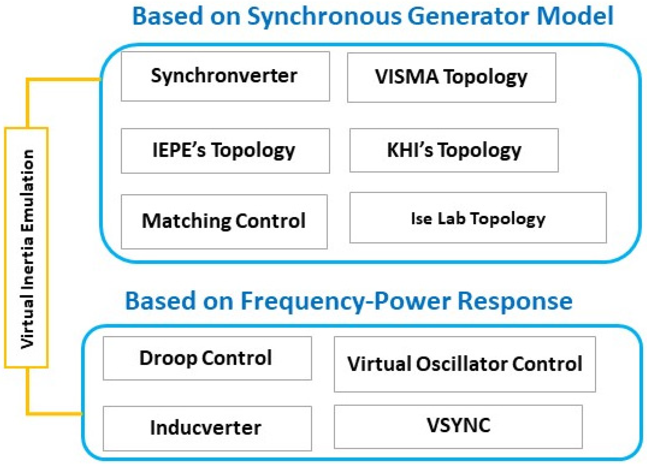
5. Grid-Forming Converters Topologies
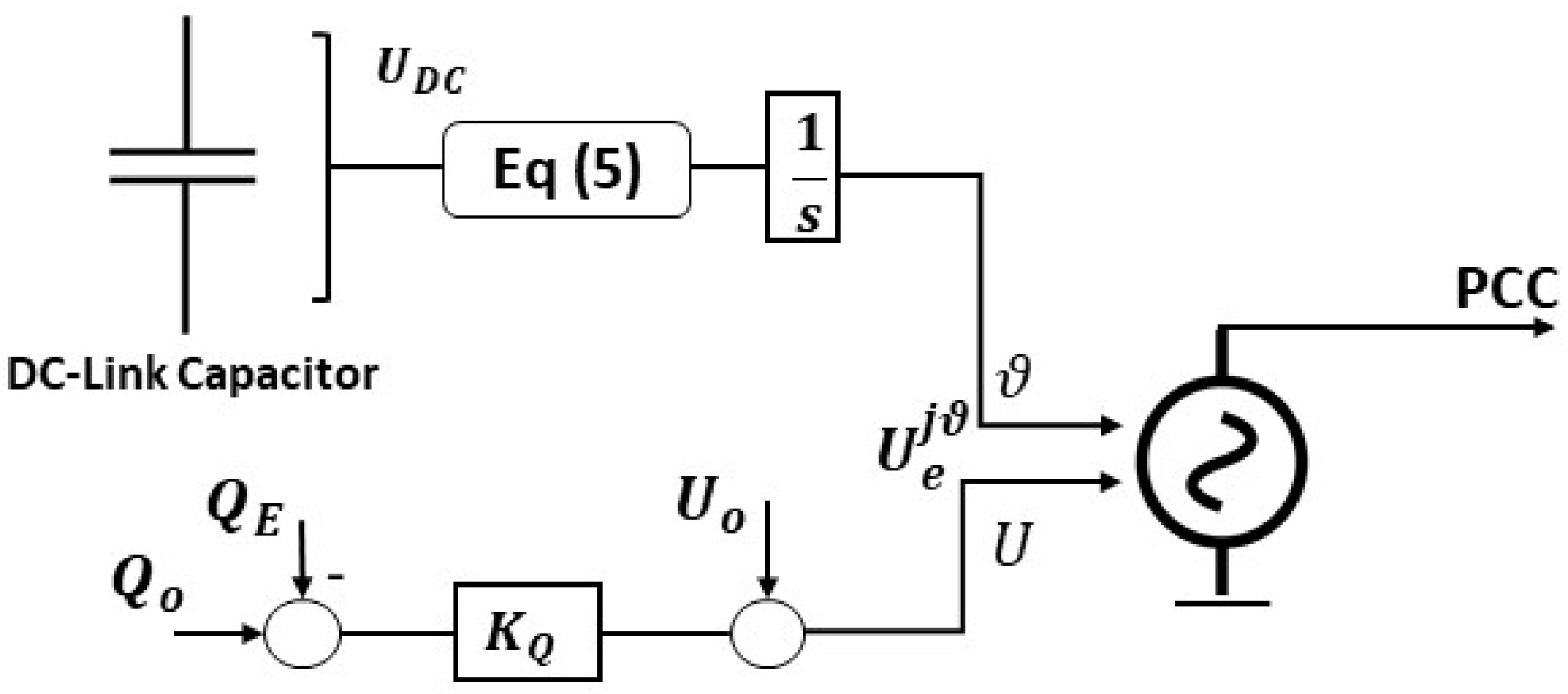
Various topologies and configurations of grid-forming converters can be found in the literature. In [12], GFM converters are classified based on the controller structure. GFM converters have some distinct properties that make them the best for inverter-based grids, apart from providing inertia and strengthening the grid. This includes the independent voltage and frequency control, being able to function as an infinite bus, black start capability, suitability for weak AC grids due to low output impedance, etc. [13]. In this section, GFM converters capable of inertia emulation are discussed.

5.1. Synchronverter

The synchronverter, also known as a virtual synchronous machine (VSM), operates on the principle of the synchronous machine virtually following the famous swing equation shown in Equation (1).
 
J w ˙ = T m + T d T e
T m = m e c h a n i c a l   T o r q u e ,
T e = E l e c t r i c a l   t o r q u e   i n d u c e d   b y   c u r r e n t ( i t   o p p o s e s   p r i m e   m o v e r )
T d = d r o o p   t o r q u e ,
( T m + T d ) = a c t i v e   t o r q u e   o r   p r i m e   m o v e r   t o r q u e
The synchronverter can be classified into two major blocks, i.e., control and power block. Power block consists on the converter and its interconnection with the grid, while the control block is responsible for the calculation, regulation, and generation of PWM pulses for the gate driver of the converter, as depicted in Figure 6.
T e = M f i f i ,   s i n θ ˜
 
e = M f i f w   s i n θ ˜
  = v q i d v d i q
Figure 6. Synchronverter.
Here, mechanical inertia is replaced by the power of a DC bus. It also models the other attributes of SG, such as disturbance response and inertia emulation. The unique feature of the synchronverter is that all the parameters of SG are modeled in a synchronverter; thus, all the matured and existing control strategies designed for SG can be applied to a synchronverter [14]. Moreover, it depicts the same dynamics as the SG and can be operated as a synchronous motor, which sets it apart from other machine-emulating methods. A synchronverter can be operated in GFM and GFL mode, as it does not follow a voltage or current reference. In [15], an improved self-synchronized version of synchronverter was proposed. The control architecture of the synchronverter is presented in Figure 7.
Figure 7. Synchronverter control architecture.

5.2. Matching Control

The structural similarities between the SG and inverter model realize the matching control topology. It controls the DC link, similar to how a mechanical rotor is controlled. The difference between synchronverter and matching control is that, in the latter, to drive the harmonic frequency oscillator, instead of using an SG model, a DC link is utilized. A controller drives the inverter modulation based on the embedded internal oscillator model. To monitor the power balance, the DC link voltage is used. By controlling the DC current, active power tracking can be achieved, which results in the oscillator frequency and voltage control. Matching control only utilizes DC-side measurements which results in no processing delays [16]. In simple words, the duality of the DC voltage of the converter and the machine’s angular velocity can be referred as matching control. It considers the DC-link capacitor as a storage device, similar to the concept of inertia. So, the capacitor voltage is used to regulate the frequency of the converter bridge [17]. The control is depicted in Equation (5):
 
ω = ω g + s + K T K j s + K D [ ( U D C ) 2 ( U D C r e f ) 2 ]  
where ω is the output frequency, ωg is the grid frequency, and UDC is the voltage of the DC-link capacitor. The control architecture is shown in Figure 8.
Figure 8. Control architecture of matching control GFM converter.

5.3. Virtual Oscillator Control (VOC)

VOC is based on the emulation of the non-linear oscillators’ dynamics in the inverter control. It is much similar to matching control in terms of the emulation of non-linear oscillations’ dynamics. The difference is that, instead of using phasors, the VOC uses time-domain signals for voltage regulation. Understanding the oscillator model is a prerequisite to understanding the VOC approach. The non-linear dead zone oscillator on which the VOC method is based is shown in Figure 9 [18]. The oscillator consists of a resonant LC tank through which the frequency can be set. The non-linear current source helps to sustain the oscillations, and the resistor R acts as a damping element. Most oscillators can be modeled by connecting a passive impedance parallel to a non-linear current source. Figure 9 represents the topological approach for the VOC.
Figure 9. Dead zone oscillator.
The PWM signals for the converter are generated using the oscillator’s terminal voltage. It is to be noted that the oscillator must operate in the quasi-harmonic region by following Equation (6):
 
ε = L C ( σ 1 R ) > 0  
The unique characteristics of VOC include possessing all the features of droop control, while providing superior voltage regulation and load-sharing capabilities. The only point that needs attention and further research is the trade-off between frequency deviation and response time for a VOC.

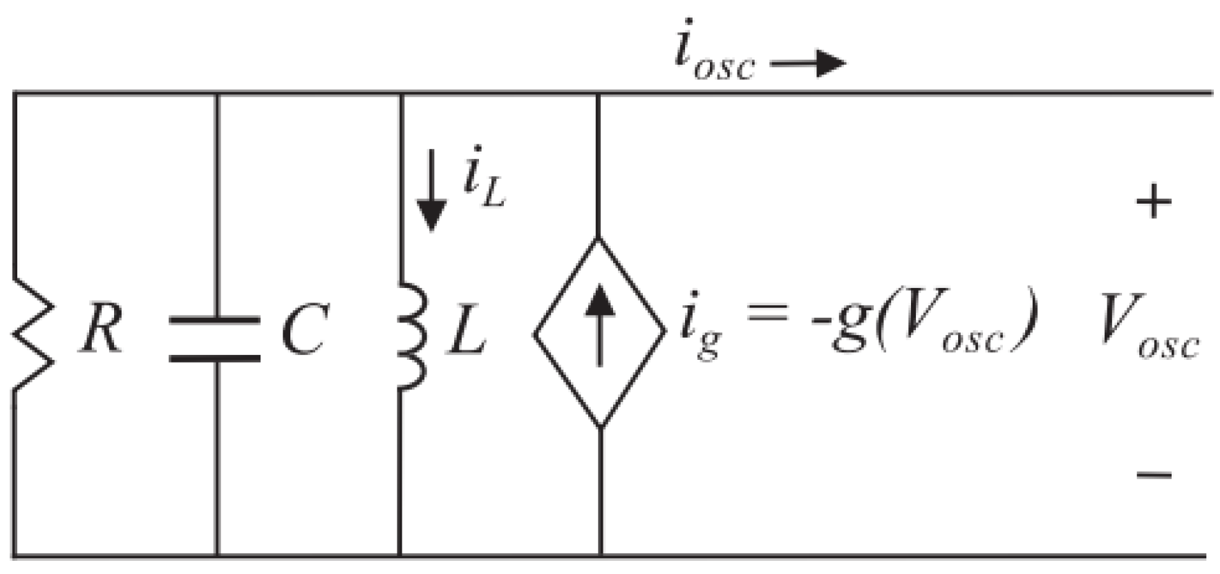
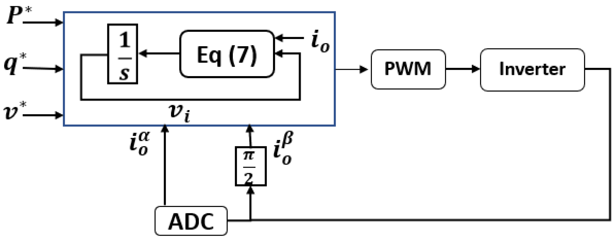
5.4. Dispatchable Virtual Oscillator (dVOC)

Virtual oscillator control provides enhanced performance in dynamic voltage regulation and maintains the droop control law [19], but it is still a mystery how to configure the inverter’s power injections when they lack programmable power setpoints. A good candidate for such a scenario is dVOC.
Dispatchable VOC allows the user to set power setpoints for the inverter. In the case of absent set points, dVOC operates in the VOC mode and provides all the needed functions. vdq is the reference voltage generated, following the control law from Equation (7):
 
d d t v d q = w r e f J v d q + η ( K v d q R ( k ) i d q + α v r e f 2 ( v r e f 2 v d q 2 ) v d q )  
where R(k) is the rotation matrix:
 
R ( k ) = [ c o s ( k ) s i n ( k ) s i n ( k ) c o s ( k ) ]  
where K is the inductance-to-resistance ratio. η and α are virtual oscillator design parameters; ωref and vref are frequency and voltage references, respectively; idq is the measured current; and ||vdq|| is the measured voltage magnitude. The control architecture of dVOC is shown in Figure 10P, q, v represents the reference values.
Figure 10. Control architecture of dVOC.

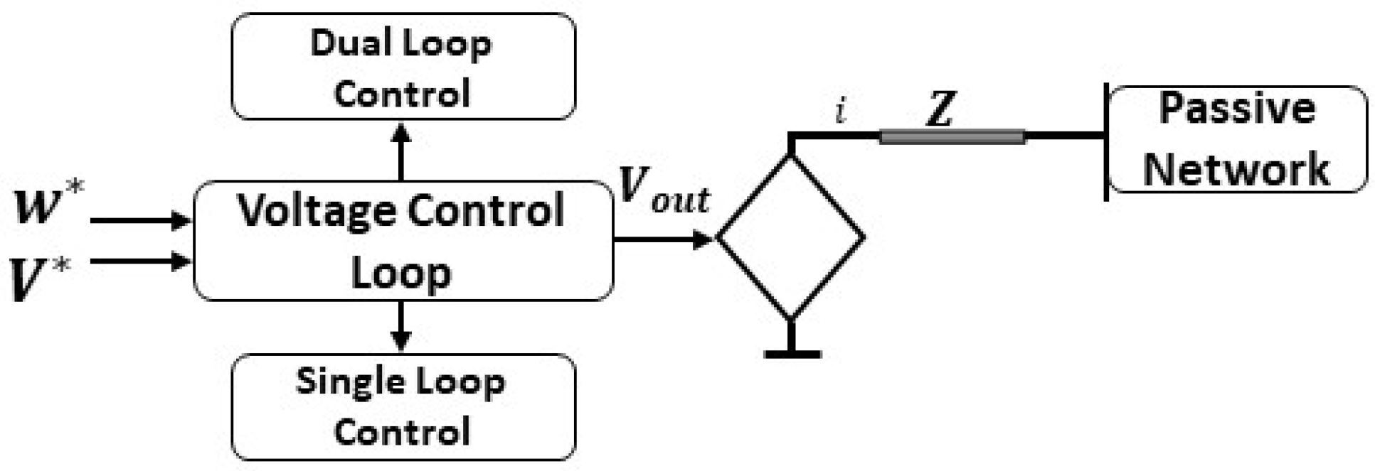
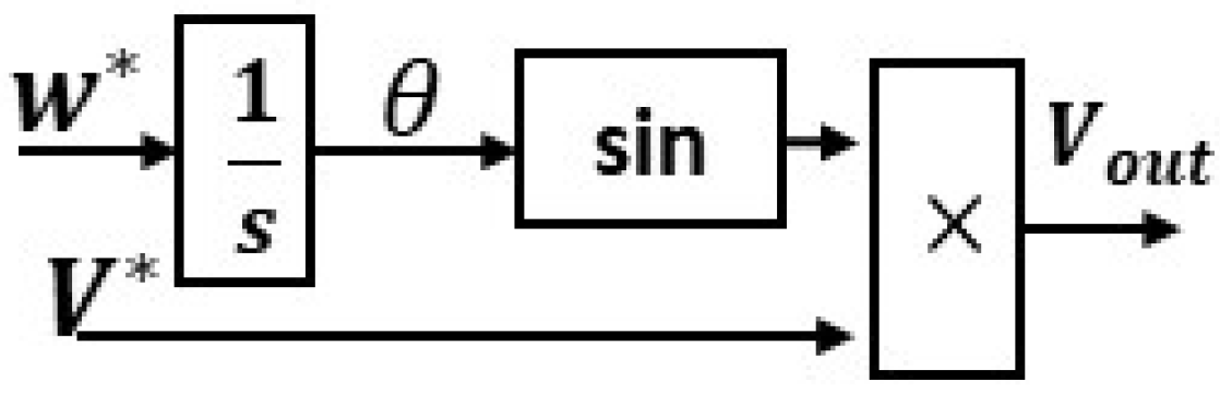
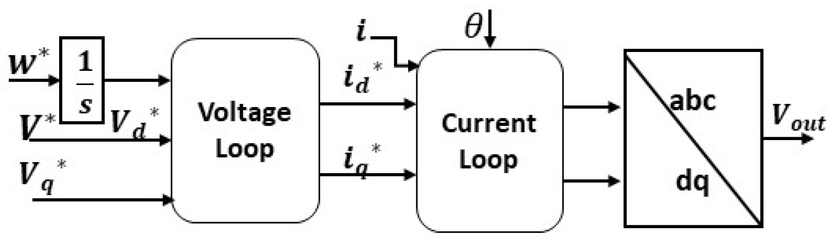
5.5. Direct Voltage (V-f) Control

V-f control is most suitable for passive grid applications, such as uninterruptible power supply and islanded grids because the output voltage and frequency remain under closed-loop control. This GFM technique lacks power-sharing ability. Therefore, it has limitations when applied to active grids. As depicted in Figure 11, V-f control can be presented as a controlled voltage source, having an output impedance in series. W, V represents the reference values.
Figure 11. V-f control architecture.
V-f control have two modes, i.e., a single or dual-loop control. In the case of single-loop control, the reference value of the frequency and voltage generates the voltage output (Vout) of the converter. For a dual-loop control, the output voltage (Vout) comes through cascaded loops of current and voltage, which give current-limiting ability to dual-loop control. The single loop mode is applied for DC-link voltage control in GFL applications, and it can be used for AC voltage regulation in GFM applications. This control strategy is beneficial when implemented in a master–slave topology. Where multiple GFL converters follow a master or a leader, the leader is a GFM converter. In the case of more than one GFM converter in a network, the phase synchronization angle should be shared amongst all of them via communication channels, which disables this control scheme’s decentralized operation ability. Figure 12 and Figure 13 show both the single and dual-loop control modes.
Figure 12. Single-mode V-f control.
Figure 13. Dual-mode V-f control.
The unique aspect of the grid forming converters lies in their ability to emulate inertia. Multiple topologies are reported in the literature to date; Figure 14 presents an overview of all the existing and proven virtual inertia emulation topologies. The synchronverter is explained in detail in [14][15]. Refs. [12][13][16][17] presents the matching control and the VOC is presented in [18][19]. The droop control is explained in [20][21]. The VISMA topology can be understood through [22][23]. The IEPE’s topology is presented in [24][25] is focused on KHI’s Topology The Ise topology is presented in [26][27]. The inducverter can be understood through [28] and the VSYNC is explained in [29][30]. GFM techniques can be divided into two categories, i.e., based on the SG model or on frequency power response. Both approaches have pros and cons, so the selection is dependent purely on the application and conditions. For large-signal stability, SG-based models are more promising due to accurate modeling and the mimicking of SG characteristics. The SG-based model enables the accurate emulation of the dynamics; there is no need for PLL (except for synchronization), and it is not dependent on the frequency derivative. The challenges include numerical instability issues, voltage source implementation, and over-current protection.
Figure 14. Classification overview of inertia-emulating topologies.
Frequency power response has a much simpler and straightforward implementation. It has an inherent over current protection and has current source implementation. The drawbacks include instability issues due to the presence of PLL (especially in weak grids). Moreover, it also needs a frequency derivative and is more susceptible to noise.

This entry is adapted from the peer-reviewed paper 10.3390/en15144937

References

  1. Bottrell, N.; Green, T.C. Comparison of current-limiting strategies during fault ride-through of inverters to prevent latch-up and wind-up. IEEE Trans. Power Electron. 2014, 29, 3786–3797.
  2. Hou, X.; Sun, Y.; Zhang, X.; Lu, J.; Wang, P.; Guerrero, J.M. Improvement of frequency regulation in VSG-based AC microgrid via adaptive virtual inertia. IEEE Trans. Power Electron. 2020, 35, 1589–1602.
  3. Sato, T.; Asharif, F.; Umemura, A.; Takahashi, R.; Tamura, J. Cooperative Virtual Inertia and Reactive Power Control of PMSG Wind Generator and Battery for Improving Transient Stability of Power System. In Proceedings of the 2020 IEEE International Conference on Power and Energy (PECon), Penang, Malaysia, 7–8 December 2020; pp. 101–106.
  4. Alegria, E.; Brown, T.; Minear, E.; Lasseter, R.H. CERTS Microgrid Demonstration with Large-Scale Energy Storage and Renewable Generation. IEEE Trans. Smart Grid 2014, 5, 937–943.
  5. Golestan, S.; Guerrero, J.M.; Vasquez, J.C. Three-Phase PLLs: A Review of Recent Advances. IEEE Trans. Power Electron. 2017, 32, 1894–1907.
  6. Guerrero, J.M.; Vasquez, J.C.; Matas, J.; De Vicuña, L.G.; Castilla, M. Hierarchical Control of Droop-Controlled AC and DC Microgrids A General Approach Toward Standardization. IEEE Trans. Ind. Electron. 2011, 58, 158–172.
  7. Huang, S.-H.; Schmall, J.; Conto, J.; Adams, J.; Zhang, Y.; Carter, C. Voltage control challenges on weak grids with high penetration of wind generation: Ercot experience. In Proceedings of the 2012 IEEE Power and Energy Society General Meeting, San Diego, CA, USA, 22–26 July 2012; IEEE: Piscataway, NJ, USA, 2012; pp. 1–7.
  8. IEEE Std 1204–1997; IEEE Guide for Planning DC Links Terminating at AC Locations Having Low Short-Circuit Capacities. IEEE: Piscataway, NJ, USA, 1997; pp. 1–216.
  9. North American Electric Reliability Corporation (NERC). Protection System Response to Power Swings; NERC System Protection and Control Subcommittee Report; NERC: Atlanta, GA, USA, 2013.
  10. Erickson, M.J.; Jahns, T.M.; Lasseter, R.H. Improved Power Control Bandwidth of Grid-Forming Sources in a CERTS Microgrid. In Proceedings of the 2012 IEEE Energy Conversion Congress and Exposition, Raleigh, NC, USA, 15–20 September 2012; Institute of Electrical and Electronics Engineers: Piscataway, NJ, USA, 2012; pp. 2366–2373.
  11. Hossain, M.; Pota, H.; Issa, W.; Hossain, M. Overview of ac microgrid controls with inverter-interfaced generations. Energies 2017, 10, 1300.
  12. NERC. Inverter-Based Resource Performance Guideline; NERC: Atlanta, GA, USA, 2018.
  13. Deng, Z.; Wang, H.; Qin, Y.; Zhang, J.; Zhu, C.; Cai, X. Matching-Control of Wind Power System Based on Current Source Converter. In Proceedings of the 10th Renewable Power Generation Conference (RPG 2021), Online, 14–15 October 2021; pp. 144–150.
  14. Zhong, Q.; Weiss, G. Synchronverters: Inverters That Mimic Synchronous Generators. IEEE Trans. Ind. Electron. 2011, 58, 1259–1267.
  15. Zhong, Q.; Nguyen, P.; Ma, Z.; Sheng, W. Self-Synchronized Synchronverters: Inverters without a Dedicated Synchronization Unit. IEEE Trans. Power Electron. 2014, 29, 617–630.
  16. Dhople, S.V.; Johnson, B.B.; Hamadeh, A.O. Virtual Oscillator Control for voltage source inverters. In Proceedings of the 2013 51st Annual Allerton Conference on Communication, Control, and Computing (Allerton), Monticello, IL, USA, 2–4 October 2013; pp. 1359–1363.
  17. Seo, G.-S.; Colombino, M.; Subotic, I.; Johnson, B.; Gross, D.; Dorfler, F. Dispatchable Virtual Oscillator Control for Decentralized Inverter-Dominated Power Systems: Analysis and Experiments. In Proceedings of the 2019 IEEE Applied Power Electronics Conference and Exposition (APEC), Anaheim, CA, USA, 17–21 March 2019; National Renewable Energy Laboratory: Golden, CO, USA, 2019.
  18. Tayyebi, A.; Dörfler, F.; Kupzog, F.; Miletic, Z.; Hribernik, W. Grid-forming converters—Inevitability, control strategies and challenges in future grid applications. In Proceedings of the Workshop on Microgrids and Local Energy Communities (CIRED 2018), Ljubljana, Slovenia, 7–8 June 2018.
  19. Kim, J.; Guerrero, J.M.; Rodriguez, P.; Teodorescu, R.; Nam, K. Mode Adaptive Droop Control With Virtual Output Impedances for an Inverter-Based Flexible AC Microgrid. IEEE Trans. Power Electron. 2011, 26, 689–701.
  20. Hesse, R.; Turschner, D.; Beck, H. Micro grid stabilization using the virtual synchronous machine (VISMA). Renew. Energy Power Qual. J. 2009, 1, 676–681.
  21. Chen, Y.; Hesse, R.; Turschner, D.; Beck, H. Dynamic properties of the virtual synchronous machine (VISMA). Renew. Energy Power Qual. J. 2011, 11, 755–759.
  22. Chen, Y.; Hesse, R.; Turschner, D.; Beck, H. Comparison of methods for implementing virtual synchronous machine on inverters. In Proceedings of the International Conference on Renewable Energies and Power Quality (ICREPQ’12), Santiago de Compostela, Spain, 28–30 March 2012; pp. 734–739.
  23. Hirase, Y.; Abe, K.; Sugimoto, K.; Shindo, Y. A grid connected inverter with virtual synchronous generator684 model of algebraic type. IEEE Trans. Power Energy 2012, 132, 371–380.
  24. Li, M.; Huang, W.; Tai, N.; Duan, D. Virtual Inertia Control of the Virtual Synchronous Generator: A Review. arXiv 2021, arXiv:2109.07590.
  25. Liu, J.; Miura, Y.; Ise, T. Dynamic characteristics and stability comparisons between virtual synchronous generator and droop control in inverter-based distributed generators. In Proceedings of the 2014 International Power Electronics Conference (IPEC—Hiroshima 2014—ECCE ASIA), Hiroshima, Japan, 18–21 May 2014; pp. 1536–1543.
  26. Ashabani, M.; Freijedo, F.D.; Golestan, S.; Guerrero, J.M. Inducverters: PLL-Less Converters with Auto-Synchronization and Emulated Inertia Capability. IEEE Trans. Smart Grid 2016, 7, 1660–1674.
  27. Driesen, J.; Visscher, K. Virtual synchronous generators. In Proceedings of the 2008 IEEE Power and Energy Society General Meeting—Conversion and Delivery of Electrical Energy in the 21st Century, Pittsburgh, PA, USA, 20–24 July 2008; pp. 1–3.
  28. Morren, J.; Pierik, J.; de Haan, S.W.H. Inertial response of variable speed wind turbines. Electr. Power Syst. Res. 2006, 76, 980–987.
  29. Günther, K.; Sourkounis, C. Investigation of Virtual Synchronous Machine Control for the Grid-Side Converter of Wind Turbines with Permanently Excited Synchronous Generator. In Proceedings of the IECON 2019—45th Annual Conference of the IEEE Industrial Electronics Society, Lisbon, Portugal, 14–17 October 2019; pp. 2395–2401.
  30. Shang, L.; Hu, J.; Yuan, X.; Huang, Y. Improved virtual synchronous control for grid-connected VSCs under grid voltage unbalanced conditions. J. Mod. Power Syst. Clean Energy 2019, 7, 174–185.
More
This entry is offline, you can click here to edit this entry!
Video Production Service