Your browser does not fully support modern features. Please upgrade for a smoother experience.
Submitted Successfully!
 +1 credit
Thank you for your contribution! You can also upload a video entry or images related to this topic.
For video creation, please contact our Academic Video Service.
| Version | Summary | Created by | Modification | Content Size | Created at | Operation |
|---|---|---|---|---|---|---|
| 1 | Yuanqing Zhu | -- | 1796 | 2022-05-18 08:20:53 | | | |
| 2 | Yuanqing Zhu | Meta information modification | 1796 | 2022-05-18 08:23:07 | | | | |
| 3 | Conner Chen | Meta information modification | 1796 | 2022-05-18 08:28:00 | | | | |
| 4 | Yuanqing Zhu | Meta information modification | 1796 | 2022-05-18 08:49:22 | | |
Video Upload Options
We provide professional Academic Video Service to translate complex research into visually appealing presentations. Would you like to try it?
Cite
If you have any further questions, please contact Encyclopedia Editorial Office.
Zhu, Y.; Zhou, W.; , . Classification of the Marine Selective Catalytic Reduction Systems. Encyclopedia. Available online: https://encyclopedia.pub/entry/23046 (accessed on 14 July 2026).
Zhu Y, Zhou W, . Classification of the Marine Selective Catalytic Reduction Systems. Encyclopedia. Available at: https://encyclopedia.pub/entry/23046. Accessed July 14, 2026.
Zhu, Yuanqing, Weihao Zhou, . "Classification of the Marine Selective Catalytic Reduction Systems" Encyclopedia, https://encyclopedia.pub/entry/23046 (accessed July 14, 2026).
Zhu, Y., Zhou, W., & , . (2022, May 18). Classification of the Marine Selective Catalytic Reduction Systems. In Encyclopedia. https://encyclopedia.pub/entry/23046
Zhu, Yuanqing, et al. "Classification of the Marine Selective Catalytic Reduction Systems." Encyclopedia. Web. 18 May, 2022.
Copy Citation
The marine SCR system is mainly composed of a urea solution injection system, mixer, SCR reactor, measurement system, and soot blowing system. The urea solution injection system is composed of a urea storage tank, urea injection pump, nozzle, valve, and pipeline. Additionally, a static mixer is arranged in the exhaust pipe of the marine SCR system to improve the mixing uniformity of exhaust gas and ammonia gas.
SCR system
marine low-speed diesel engine
Classification
1. Classification of the Marine Selective Catalytic Reduction (SCR) Systems
The marine SCR system is mainly composed of a urea solution injection system, mixer, SCR reactor, measurement system, and soot blowing system [1]. The urea solution injection system is composed of a urea storage tank, urea injection pump, nozzle, valve, and pipeline. Additionally, a static mixer is arranged in the exhaust pipe of the marine SCR system to improve the mixing uniformity of exhaust gas and ammonia gas. It is mainly composed of some baffles with different directions. By changing the airflow direction of the exhaust gas, it causes turbulent flow in different directions. This method can make the urea move and mix rapidly in the radial direction and increase the uniformity of the concentration distribution of the cross-section. Although the mixer can fully mix the exhaust gas and ammonia gas, it will also cause a certain pressure loss. The reactor is the core site for the selective catalytic reduction reaction, which is mainly composed of the reactor shell, catalyst, soot blowing unit, and various sensors. The catalyst in the reactor is generally a modular packaged catalyst, which can be easily replaced. At the same time, the catalyst is installed inside the reactor. The installation position and structure of the catalyst in the reactor can be designed according to the different application sites and space size of the SCR system. By optimizing the design, the mixing uniformity of ammonia gas and exhaust gas can be improved as much as possible.
The selective catalytic reduction technology uses ammonia (NH3) to reduce NOx. It selectively reacts with the NOx in diesel exhaust gas to produce harmless substances N2 and H2O within the temperature range of 280–420 °C and under the action of a catalyst, so as to achieve the purpose of removing NOx [2]. As the urea-water solution (UWS) has no significant harm and the supply system is easy to install, it is widely used as the reducing agent for selective catalytic reduction reactions [3]. At present, the decomposition reaction process of urea is generally simplified to the following reactions:
Water evaporation of urea solution:
Urea pyrolysis reaction:
Hydrolytic reaction of isocyanic acid:
Therefore, the total reaction of urea decomposition is:
The urea solution is finally decomposed to produce reaction gas NH3, which is mixed evenly with the tail gas, and enters the SCR reactor for a denitration reaction.
Due to the low exhaust temperature and high sulfur amount of the exhaust gas from the marine diesel engine, the denitration efficiency of the marine SCR system is strongly limited. At present, marine diesel SCR systems, especially two-stroke low-speed diesel SCR systems, mainly achieve higher denitration efficiency by increasing the temperature of the reaction gas to meet the requirements for marine diesel engine emission control [4].
According to the arrangement of the SCR system, the marine SCR system can be divided into the high-pressure SCR (HP-SCR) system arranged in front of the turbocharger and the low-pressure SCR (LP-SCR) system arranged after the turbocharge [5][6]. Figure 1 shows a flowchart of a HP-SCR system and a LP-SCR system on a marine diesel engine.
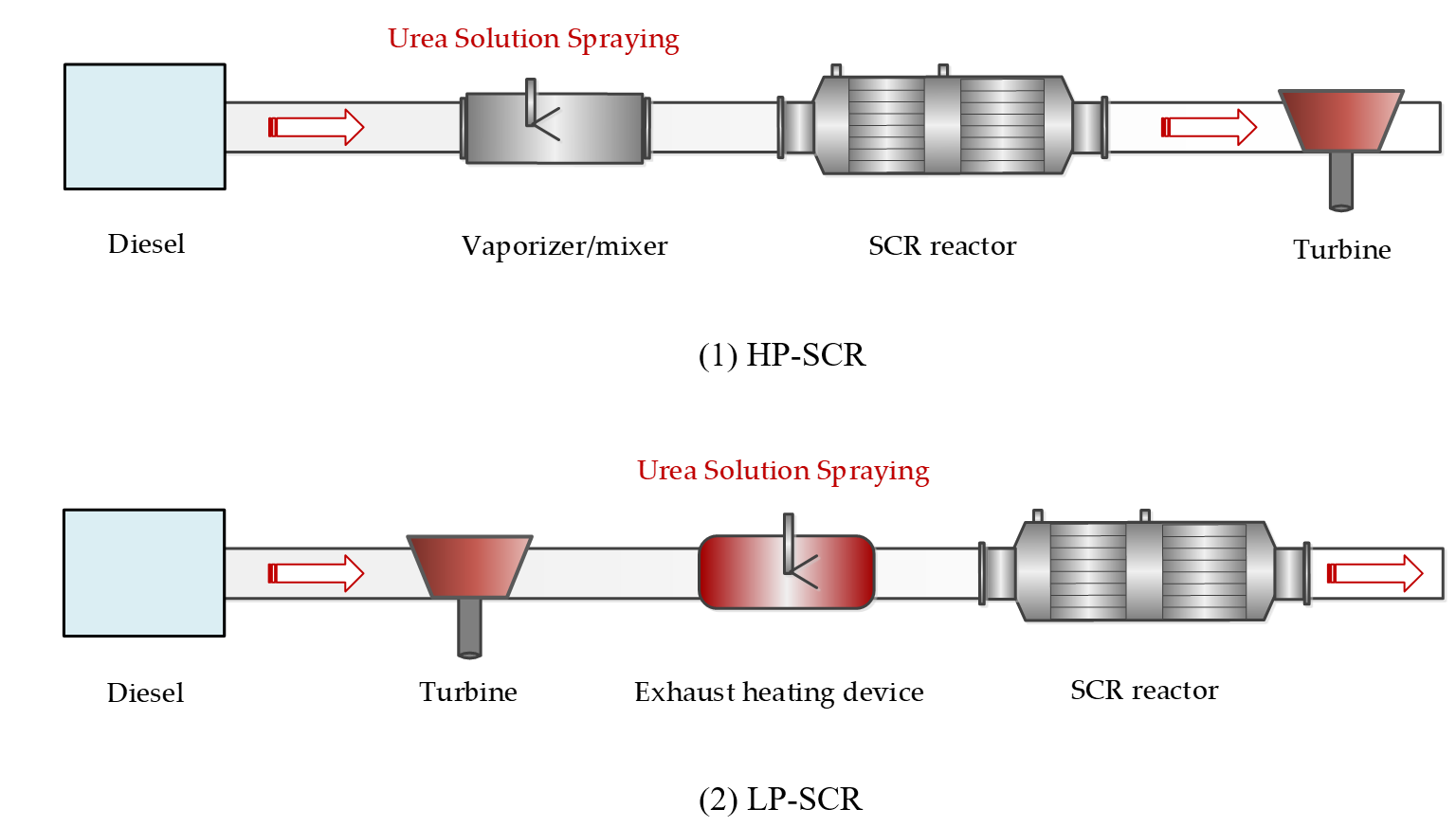
Figure 1. Flowchart of the marine diesel engine high-pressure SCR system and low-pressure SCR system [7].
2. High-Pressure SCR System
The HP-SCR system is mainly installed before the diesel turbocharger to fully increase the SCR reaction temperature [8]. This SCR system has a compact layout and high exhaust gas energy utilization rate, but it has a large impact on the working performance of diesel engines and turbochargers [9]. It is mainly used in two-stroke low-speed diesel engines burning high sulfur heavy oil.
Figure 2 shows the HP-SCR system developed by MAN, which mainly includes four parts: vaporizer/mixer, SCR reactor, auxiliary fan, and bypass valve group. The vaporizer/mixer mainly guarantees the complete evaporation and decomposition of the injected urea solution, and ensures the uniform mixing of the reducing agent NH3 and the exhaust gas. Exhaust gas in the exhaust pipe drives the turbocharger to work, and the exhaust gas temperature before and after the turbocharger differs by 50–175 °C [10]. Therefore, the SCR system in front of the turbocharger can make full use of the higher exhaust gas temperature (low pressure 500 °C) to increase the SCR system denitration efficiency [11].
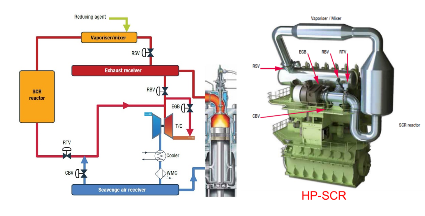
Figure 2. HP-SCR system developed by MAN [1].
Figure 3 shows the relationship between the exhaust gas temperature before the turbine and the minimum operating temperature required by the SCR system. It can be seen that when the main engine is running at low load, the temperature of the exhaust gas before the turbine is low and cannot reach the normal working temperature required by the SCR system.
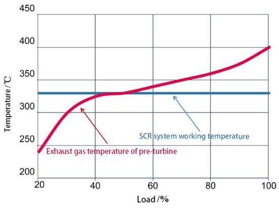
Figure 3. The relationship between the exhaust gas temperature before the turbine and the minimum operating temperature required by the SCR system [1].
In the HP-SCR system, the bypass valve group mainly includes a reactor sealing valve (RSV), a reactor throttle valve (RTV), a reactor bypass valve (RBV), an exhaust gas bypass valve (EGB), and a cylinder bypass valve (CBV). The combination of five groups of pneumatic valves controls whether the exhaust gas flows through the SCR reactor, that is, whether the exhaust gas is treated. For diesel engines that meet the IMO Tier II standard, the switch of the bypass valve group determines the working mode of the diesel engine—Tier II mode or Tier III mode [12]. Additionally, the two working modes of the diesel engine also meet the different emission standards.
In diesel Tier II mode, the RBV is opened, the RSV and the RTV are closed, the exhaust gas directly enters the turbocharger, and the SCR system is inoperative [13][14][15]. At this time, whether the EGB is opened depends on whether the NOx emissions of the diesel engine meet the IMO Tier II standard. Generally, the diesel engine produces heavy pollutants at low load, and the EGB ensures that the NOx emissions of the diesel engine meet the IMO Tier II standard [16]. In contrast, in diesel Tier III mode, the RSV and RTV are opened, the RBV is closed, and the exhaust gas flows through the vaporizer/mixer and SCR reactor and then enters turbocharger, so the SCR system is working.
The exhaust gas temperature often cannot meet the working requirements of the SCR system under low load of diesel engine, even if the SCR system is arranged in front of the turbocharger [17]. To solve such problems, a CBV is arranged between the scavenging collector and the turbocharger inlet to control the amount of fresh air entering the cylinder. When the CBV is opened, part of the fresh air will flow into the exhaust pipe, and the amount of fresh air entering the cylinder will be reduced, but the scavenging pressure will remain unchanged [18][19][20]. When the fuel consumption increases, the exhaust temperature of the diesel engine will inevitably increase, and the degree of its increase depends on the increase in fuel consumption [21]. Figure 4 shows the control chart of the bypass valve group.
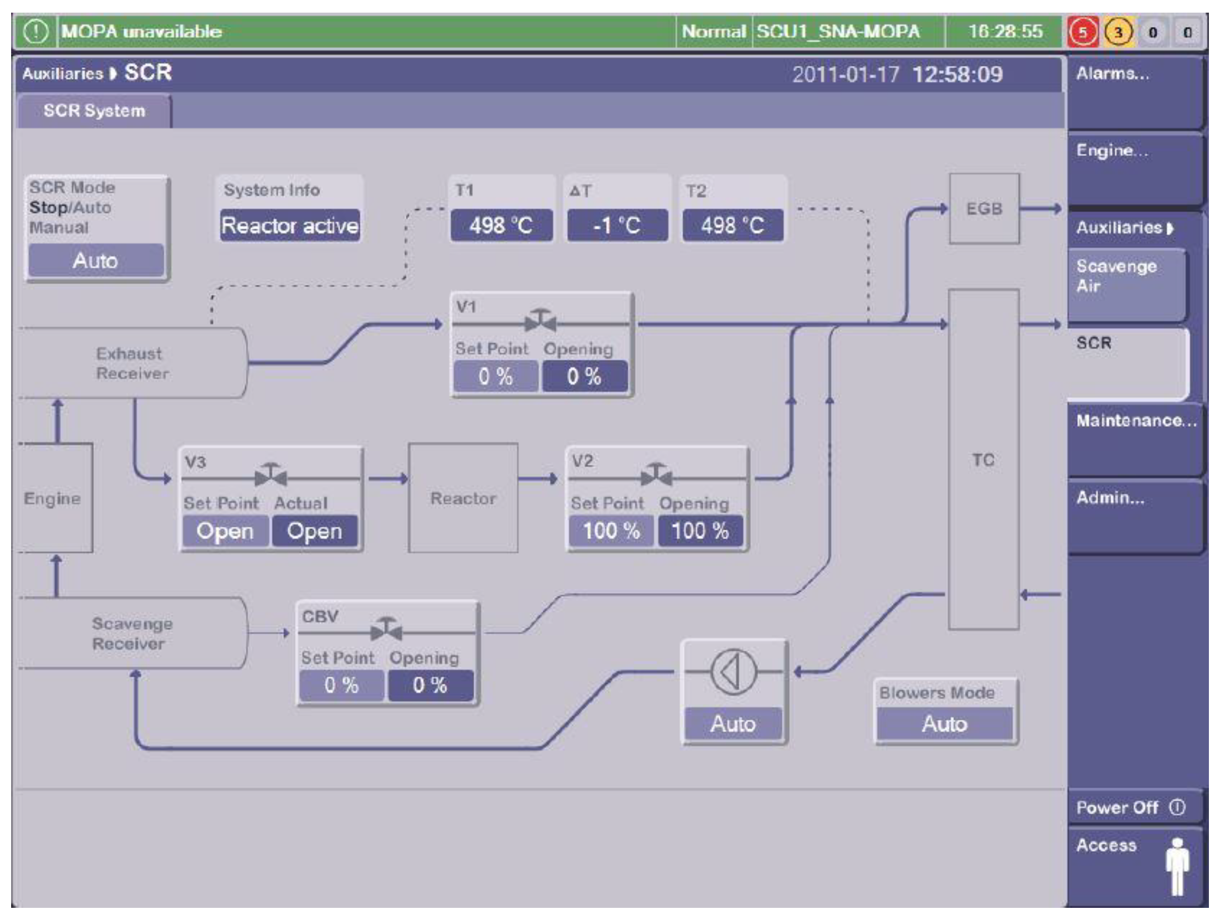
Figure 4. Control chart of the bypass valve group [6].
In diesel Tier III mode, the existence of the vaporizer/mixer and SCR reactor causes a thermal delay between the exhaust gas manifold and the turbocharger [22]. Additionally, the degree of thermal delay mainly depends on the size of the SCR reactor and the heat capacity of the catalyst. This thermal delay will inevitably affect the working performance of diesel engines and turbochargers [23]. The auxiliary fans need to be introduced to ensure the stability of the exhaust pipe [24].
3. Low-Pressure SCR System
Compared with the HP-SCR system, the LP-SCR system arranged behind the turbocharger has high adaptability and has less impact on diesel engines and turbochargers [25]. It has been widely used in medium and high speed diesel engines [26][27]. For low-speed two-stroke diesel engines, the denitration efficiency of the LP-SCR system is limited due to its low exhaust temperature [28]. Generally, in the exhaust system of low-speed diesel engines, that is, after the turbocharger and before the SCR reactor, an exhaust gas heating device is installed to increase the exhaust temperature of the diesel engine [29]. At present, there are two commonly used heating methods: electric heating and fuel injection in the exhaust pipe for re-ignition [30][31]. Both heating methods have their advantages, but their equivalent increase in fuel consumption should be controlled within 2.0 g/(kW·h).
Figure 5 shows the LP-SCR system developed by Doosan Corporation, which mainly includes four parts: static mixer (ammonia spray grid), SCR reactor, decomposition unit and bypass valve group. The decomposition unit is connected to the outlet of the SCR reactor and the inlet of the static mixer, and it includes auxiliary fan, exhaust gas heating device (burner) and evaporator [32]. Liquid ammonia or ammonia water is sprayed into the evaporator and mixed with the exhaust gas from blower into the SCR reactor [33].
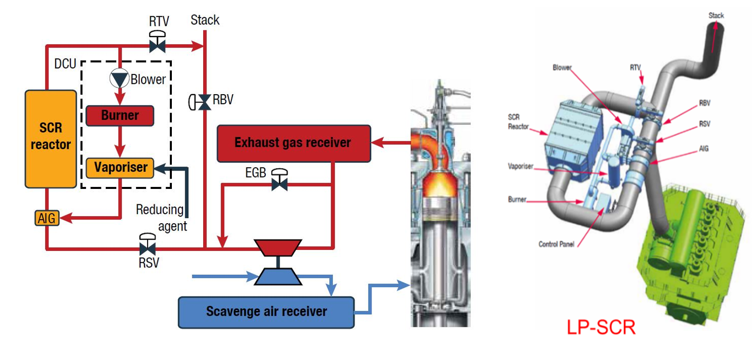
Figure 5. LP-SCR system developed by Doosan Corporation [1].
In the LP-SCR system, the bypass valve group mainly includes a reactor sealing valve (RSV), a reactor throttle valve (RTV), and an exhaust gas bypass valve (EGB). The combination of three pneumatic valves controls whether the exhaust gas flows through the SCR reactor, or whether the exhaust gas is treated. Similar to the HP-SCR system, the diesel engine matching the LP-SCR system also has two working modes—Tier II mode and Tier III mode [34][35].
The exhaust gas temperature after the turbine cannot meet the working requirements of the SCR system under the low load of the diesel engine, even if using the low sulfur fuel. To solve such problems, the CBV is placed between the exhaust manifold outlet and the turbocharger outlet to control the amount of fresh air entering the cylinder. When the CBV is opened, part of the exhaust gas on the high pressure side of the turbine will directly flow into the low pressure side of the turbine, the scavenging pressure will be reduced, and the amount of fresh air entering the cylinder will be reduced. With the increase in fuel consumption, the temperature of diesel exhaust gas will inevitably increase, and the degree of its increase depends on the increase in the fuel consumption. Even if the diesel engine uses low sulfur fuel, the formation of ammonium bisulfate or ammonium bisulfite cannot be completely avoided, but the arrangement of the decomposition unit can alleviate such problems [36].
References
- MAN B&W. MAN Emission Project Guide: MAN B&W Two-Stroke Marine Engines; MAN B&W Press: Augsburg, Germany, 2019.
- Ryu, C.; Hwang, J.; Cheon, J. The world’s first commercialized low pressure SCR system on 2-stroke engine DeNOx system. In Proceedings of the Helsinki: 28th CIMAC Congress, Helsinki, Finland, 6–10 June 2016. No. 305.
- Han, L.; Cai, S.; Gao, M.; Hasegawa, J.Y.; Wang, P.; Zhang, J.; Shi, L.; Zhang, D. Selective Catalytic Reduction of NOx with NH3 by Using Novel Catalysts: State of the Art and Future Prospects. Chem. Rev. 2019, 119, 10916–10976.
- Li, M.; Zhang, Y.; Liu, X.; Zhang, Q.; Li, Z. Numerical investigation on the urea deposit formation process in a selective catalytic reduction system of a diesel engine based on a fluid–solid coupling method. ACS Omega 2021, 6, 5921–5932.
- Tan, L.; Feng, P.; Yang, S.; Guo, Y.; Liu, S.; Li, Z. CFD studies on effects of SCR mixers on the performance of urea conversion and mixing of the reducing agent. Chem. Eng. Process. 2018, 123, 82–88.
- Christensen, H. Tier III SCR for large 2-stroke MAN B&W diesel engines. In Proceedings of the International Symposium on Marine Engineering, Kobe, Japan, 17–21 October 2011.
- Wartsila Company. Wartsila Environmental Product Guide; Wartsila Company Press: Helsinki, Finland, 2017.
- Zhu, Y.; Li, T.; Xia, C.; Feng, Y.; Zhou, S. Simulation analysis on vaporizer/mixer performance of the high-pressure SCR system in a marine diesel. Chem. Eng. Process. 2020, 148, 107819.
- Han, B.; Shen, Y.; Zhu, S.; Liu, Y.; Shen, S. Promotional effect of phosphorylation on CeSn0.8W0.6Ox/TiAl0.2Si0.1Oy for NH3-SCR of NO from marine diesel exhaust. J. Rare Earths 2016, 34, 1010–1016.
- Börnhorst, M.; Deutschmann, O. Advances and challenges of ammonia delivery by urea-water sprays in SCR systems. Prog. Energ. Combust. 2021, 87, 100949.
- Cimino, S.; Lisi, L.; Tortorelli, M. Low temperature SCR on supported MnOx catalysts for marine exhaust gas cleaning: Effect of KCl poisoning. Chem. Eng. J. 2016, 283, 223–230.
- Murakami, M.; Nakao, T. Test Results of Marine SCR System for Large Diesel Engines during Long Term Service Test. J. JIME 2015, 50, AP3.
- Xiao, L.; Lyu, L.; Zhu, N. Research and Application on the Structural Design of SCR Catalystin Marine Diesel Engine. Intern. Combust. Engines 2019, 4, 1–6.
- Yang, Z.; Jiang, G.; Zhang, X.; Wei, H. Application of selective reduction catalyst to marine diesel engine. J. Harbin Eng. Univ. 2017, 38, 1539–1544.
- Liang, R. Quantum Chemistry Research on DeNOX and Poisoning Mechanism of SCR Catalyst. Master’s Thesis, North China Electric Power University, Beijing, China, 2017.
- Qu, J.; Feng, Y.; Xu, G.; Zhang, M.; Zhu, Y.; Zhou, S. Design and thermodynamics analysis of marine dual fuel low speed engine with methane reforming integrated high pressure exhaust gas recirculation system. Fuel 2022, 319, 123747.
- Wang, Z.; Zhu, Y.; Zhou, S.; Feng, Y. Reaction mechanism and chemical kinetics of NH3-NO/NO2-SCR system with vanadium-based catalyst under marine diesel exhaust conditions. Proc. Inst. Mech. Eng. Part A J. Power Energy 2020, 234, 342–352.
- Zhang, L. The Injecting Structural Parameters Optimization and Matching Performance of SCR System for Marine Diesel Engine. Master’s Thesis, Jimei University, Xiamen, China, 2016.
- Ji, P. Research of SO2 Oxidation over SCR Catalyst and Regulatory Mechanism. Master’s Thesis, Zhejiang University, Hangzhou, China, 2016.
- Clair, S.; de Oteyza, D.G. Controlling a Chemical Coupling Reaction on a Surface: Tools and Strategies for On-Surface Synthesis. Chem. Rev. 2019, 119, 4717–4776.
- Qu, J.; Feng, Y.; Zhu, Y.; Zhou, S.; Zhang, W. Design and thermodynamic analysis of a combined system including steam Rankine cycle, organic Rankine cycle, and power turbine for marine low-speed diesel engine waste heat recovery. Energy Convers. Manag. 2021, 245, 114580.
- Peng, H.; Chen, W. The analysis and countermeasures of the system problems in SCR flue gas denitrification ammonia zone. Green Pet. Petrochem. 2019, 4, 45–48.
- Ou, S.; Min, E.; Zhang, L.; Deng, Z.; Yin, Z. Experimental Analysis on Matching Performance of SCR System for a Marine Diesel Engine. Ship Eng. 2017, 39, 66–70.
- Zheng, C. Numerical Simulation and Test Verification of the whole Process of SCR System for Marine Low Speed Diesel Engine. Master’s Thesis, China Ship Research Institute, Beijing, China, 2019.
- Gao, C.; Shi, J.; Fan, Z.; Wang, B.; Wang, Y.; He, C.; Wang, X.; Li, J.; Niu, C. “Fast SCR” reaction over Sm-modified MnOx–TiO2 for promoting reduction of NOx with NH3. Appl. Catal. A Gen. 2018, 564, 102–112.
- Xie, P.; Gao, M.; Zhang, H.; Niu, Y.; Wang, X. Dynamic modeling for NOx emission sequence prediction of SCR system outlet based on sequence to sequence long short-term memory network. Energy 2020, 190, 116482.
- Liu, G.; Cui, Y.; Ji, J.; Shen, D.; Wang, Q.; Li, C.; Luo, K. A technical method to improve NOx/NH3 mixing ratio in CR systemand its engineering applications. J. Energy Inst. 2019, 92, 1757–1764.
- Zhu, Y.; Zhang, R.; Zhou, S.; Huang, C.; Feng, Y.; Zhang, C. Performance Optimization of High-pressure SCR System in a Marine Diesel Engine. Part I: Flow Optimization and Analysis. Top. Catal. 2019, 62, 27–39.
- He, C.; Cheng, J.; Zhang, X.; Douthwaite, M.; Pattisson, S.; Hao, Z. Recent Advances in the Catalytic Oxidation of Volatile Organic Compounds: A Review Based on Pollutant Sorts and Sources. Chem. Rev. 2019, 119, 4471–4568.
- Won, J.M.; Hong, S.C. Selective Catalytic Reduction (SCR) Technology Trend for the Removal of Nitrogen Oxide from Ship Flue Gas. KIC News 2019, 22, 25–40.
- Lenka, S.C. Evaluation of Selective Catalytic Reduction for Marine Two-Stroke Diesel Engines. Master’s Thesis, Aalborg University, Aalborg, Denmark, 2010.
- Andreas, D.; Mirko, B.; Joachim, H.; Bader, I.; Struckmeier, D.; Baydak, M.; Losher, R.; Stiesch, G. The MAN SCR System-More Than Just Fulfilling IMO Tier III. In Proceedings of the CIMAC Congress 2016, Helsinki, Finland, 6–10 January 2016; Ppaer No. 26. Available online: https://www.researchgate.net/publication/304525249_The_MAN_SCR_System_-_More_Than_Just_Fulfilling_IMO_Tier_III (accessed on 26 April 2022).
- Federico, C. Selective Catalytic Reduction System for Marine Applications: Dynamic Modelling and System Integration. Master’s Thesis, Delft University of Technology, Delft, The Netherlands, 2018.
- Langeslay, R.R.; Kaphan, D.M.; Marshall, C.L.; Stair, P.C.; Sattelberger, A.P.; Delferro, M. Catalytic Applications of Vanadium: A Mechanistic Perspective. Chem. Rev. 2019, 119, 2128–2191.
- Zhao, Y.; Sun, Z.; Zeng, Y. Research progresses of low temperature SCR denitration catalyst. Environ. Prot. Chem. Ind. 2019, 39, 1–5.
- Jensen-Holm, H.; Castellino, F.; White, N.T. SCR DeNOx catalyst considerations when using biomass in power generation. In Proceedings of the Power Plant Air Pollutant Control “MEGA” Symposium, Washington, DC, USA, 30 August–2 September 2010.
More
Information
Subjects:
Engineering, Environmental
Contributors
MDPI registered users' name will be linked to their SciProfiles pages. To register with us, please refer to https://encyclopedia.pub/register
:
View Times:
6.6K
Entry Collection:
Environmental Sciences
Revisions:
4 times
(View History)
Update Date:
18 May 2022
Table of Contents


Notice
You are not a member of the advisory board for this topic. If you want to update advisory board member profile, please contact office@encyclopedia.pub.
OK
Confirm
Only members of the Encyclopedia advisory board for this topic are allowed to note entries. Would you like to become an advisory board member of the Encyclopedia?
Yes
No
${ textCharacter }/${ maxCharacter }
Submit
Cancel
Back
Comments
${ item }
|
${ item.createdUser.fullName }
${ item.createdAt }
${ item.vote }
${ item.reply }
Delete
${ reply.createdUser.fullName }
${ reply.createdAt }
${ reply.vote }
Delete
There is no reply to this comment~
${ item.replyTextCharacter }/${ item.replyMaxCharacter }
Submit
Cancel
More
No more~
There is no comment~
${ textCharacter }/${ maxCharacter }
Submit
Cancel
${ selectedItem.replyTextCharacter }/${ selectedItem.replyMaxCharacter }
Submit
Cancel
Confirm
Are you sure to Delete?
Yes
No