By using higher frequencies, such as 2–10 kHz, the capacitance of a coating can be monitored. In order to calculate the capacitance of the coating (
Cc), the equation
CC=ω√Zsinθ−1.
is used, where ω is the angular frequency
[15][16]. In this frequency range, almost no current flows through the resistance, but all of the current passes through the capacitor whose impedance becomes very low
[15]. Moreover, Brasher and Kingsbury
[17] showed that the volume percent of water within the coating can be calculated by high-frequency EIS. With the initiation of corrosion and the further deterioration of a coating’s barrier properties, the equivalent models become more complex
[1][18][19].
Amirian and Thienyl
[19] reviewed all of the fundamentals and the instrumentation and use of EIS for the evaluation of organic coatings.
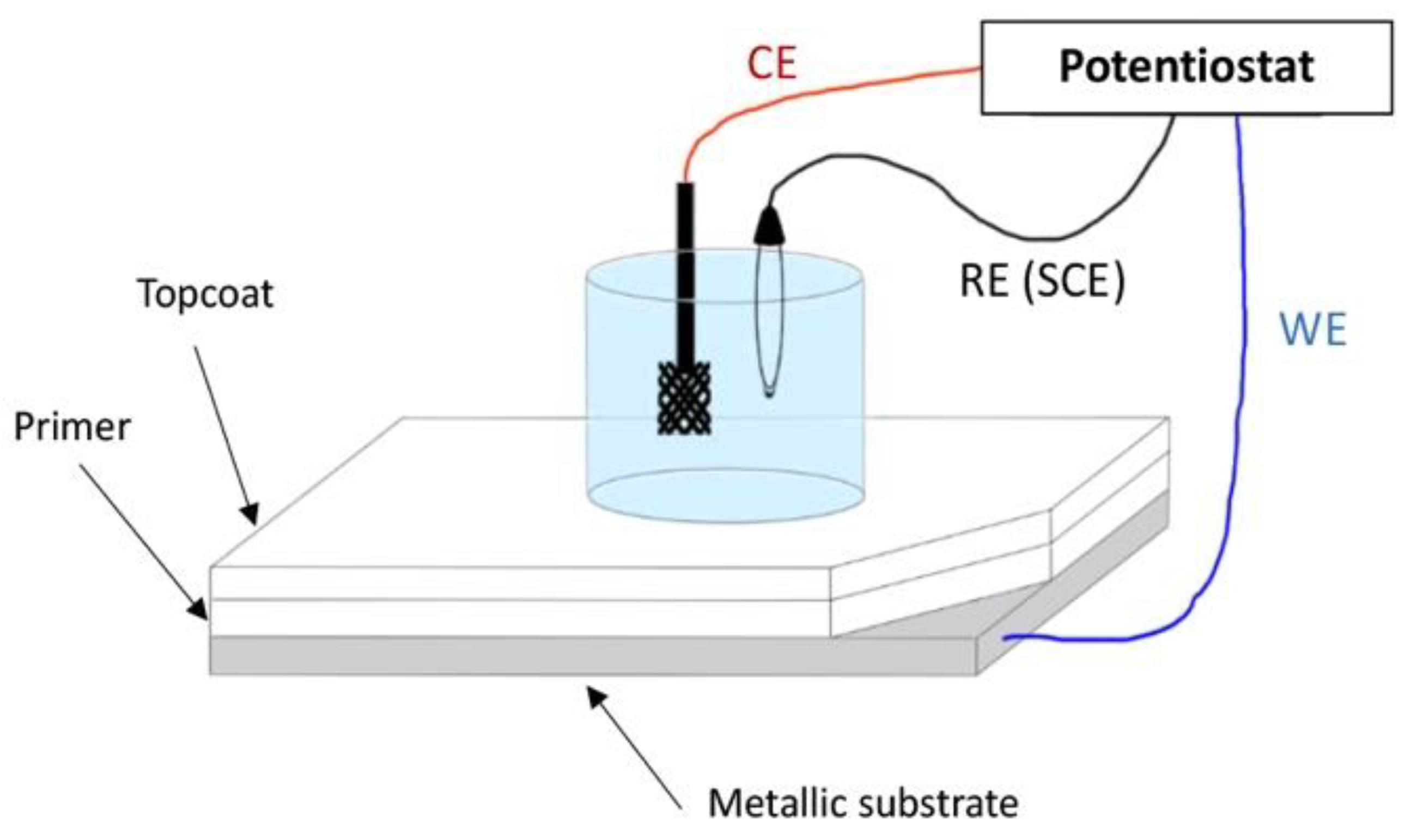
Figure 1 shows the typical setup that is used for EIS measurements with three electrodes, a reference electrode (RE), a counter electrode (CE), a working electrode (WE) and an electrolyte solution immersion cell. Due to the complexity of the operational setup, EIS was initially not suitable for a use in the field, let alone during the service life of a coating. Therefore, the simplification and miniaturisation of the measuring systems were compulsory, which are now being progressively achieved.
Figure 1. A scheme of the traditional benchtop EIS configuration and setup (personal drawing; inspiration from
[20][21]).
Professor G. Davis has been working on the development of EIS-based coatings and corrosion monitoring sensors for over three decades. Davis et al.
[22] developed two in situ sensors, one sensor was permanently attached to the surface and one was hand-held, to monitor the inaccessible areas of a structure and test panels in environmental chambers, such as a salt fog chamber, respectively. It was found that the hand-held sensor is more suitable for conducting spot checks of specimens without the permanent sensor or in areas where permanent sensors are not desired for the reasons of aerodynamics or visual appearance.
-
The uptake of moisture by the coating,
-
Corrosion incubation time,
-
The corrosion of the substrate.
Some years later, Davis et al.
[23] presented the evolution of their electrochemical impedance-based in situ sensor that is capable of detecting coating deterioration and substrate corrosion underneath the coating. It is a sensor that can be used without the need for portable cells, disordered electrolytes, and remote electrodes. Again, two versions of the sensor were presented: a permanent electrode sensor that is suitable for inaccessible areas and a portable hand-held sensor. Both proved to be capable of detecting coating deterioration at very early stages in various accelerated tests and monitoring corrosion in service, allowing condition-based maintenance to be implemented and reducing the probability of failure. The most important breakthrough was that the sensor can also be operated remotely, as it features the option for a wireless connection to a central unit that can display the representative data. The proposed miniaturised and electronic solution was a very remarkable and important step forwards in the development of remote live coating SHM (or coating health monitoring (CHM)) sensors, which notably reduces the size and difficulty of operation of the EIS measuring system.
Its only drawback is that it cannot be totally integrated into the coating system; indeed, it works when it is attached to the outer surface, hence influencing aesthetics and aerodynamics. Their system was later tested to monitor (SHM) anticorrosion coatings in US army ground vehicles
[23].
In these conditions, conventional EIS requires the specimen to be immersed in an electrolyte and the use of a remote counter together with reference electrodes. This setup was adapted to the lab scale for small samples and proper immersion conditions. However, larger specimens require beakers without bottoms that are able to be clamped onto specimens and filled with electrolyte. EIS spectra are obtained after both reference electrodes and counters are inserted into the electrolyte. Sometimes, it is necessary to use gels or electrolyte-impregnated sponges instead of a liquid electrolyte. This makes measurements in the field possible, in addition to those performed in the lab, provided that an accessible, flat, smooth, and horizontal surface can be used. This allows users to obtain a local indication of the health of the coating in the area that was wetted by the electrolyte. However, this multistep protocol has been found to be time-consuming. Moreover, too long of an exposure time to the electrolyte can artificially generate damage to the coating during exposition to ambient conditions. Later, Davis et al. also showed that the area being probed by the in-situ sensors depends on the wetness of the surface. A dry surface provides a localised measurement while a wet surface increases surface conductivity and allows the sensor to detect defects that are away from the sensor electrode. Accordingly, the detection area can be controlled by selectively wetting the surface with water. Under laboratory conditions, Davis’s team were able to detect coating defects up to 15 feet (4.5 m) away. Despite the evident step forwards in EIS-based technology and coating health assessment that has been brought about by Professor Davis’s lifelong work, one main drawback had not been addressed yet: the sensor cannot be fully integrated into an anticorrosion coating system. Instead, it works when it is attached to the outer surface, hence influencing the aesthetic appearance and aerodynamics.
In parallel with Davis’s work, many other routes were being explored with the aim of simplifying and reducing the size and paraphernalia of EIS measuring montages. The scientific community went after a clear goal: coating-embedded EIS technology. Since the early 2000s, researchers have tried to integrate electrodes into coatings to monitor their behaviour. Nevertheless, to be embedded, the electrodes need to be small in size, typically below 1 mm thick. The material for the reference electrodes also must be conductive, stable for chemical and thermal solicitations and resistant to long-term field use and manufacture processing; thus, noble metals are often chosen, such as platinum, gold, silver, and nickel. In
[24], Kittel et al. used a nickel grid that was embedded inside a coating in order to separate the contribution of the top layer, which was in contact with the environment, and the inner layer, which was in contact with the substrate, from the total impedance of the system. In
[21], Merten et al., with the collaboration of Professor Bierwagen, used micron-scale silver wire for silver/silver chloride-embedded pseudo-reference electrodes. In all cases, a metallic substrate acting as a working electrode was still compulsory. Furthermore, a counter-electrode that was immersed in an electrolyte solution was required to use the external on-surface montage, which consisted of an attached glass cell containing the solution and the CE to perform the measurements. A flat surface was also needed to properly attach the cell.
In
[10], Kittel et al. used the same strategy, but with a gold electrode that was embedded in-between the coating layers. What is remarkable in this work is that a measurement setup could include a two-electrode EIS (2E-EIS) without a substrate, such as a platinum mesh that could act as the RE and the CE (denoted as RE/CE). When a metallic substrate was not available, as in conditions in the field, the experiment had to be configured in a way that allowed the current to flow between the CE and WE. Initial attempts with the CE and WE located on both sides of a coating film coupled with electrolyte immersion cells were conducted in the laboratory
[25]. Despite not yet being applicable to a coated substrate in the field, this novel configuration opened the door to in situ embedded-electrode EIS measurements in the field.
In
[26][27], Allahar et al. demonstrated that the non-substrate 2E-EIS with an embedded RE/CE and WE in between the primer and top-coat layers can, in fact, be used to obtain information about the metallic substrate. In other words, their results demonstrated the feasibility of monitoring the coated metallic substrate without the same substrate itself being an electrode. It was hypothesised and demonstrated that the current between the coating-embedded electrodes also flows through the metallic substrate despite it not being an electrode or being in contact with the electrodes.
The goal of embedded EIS coating sensing was thus achieved and paved the way for embedded coating health monitoring sensors. Some other examples can be found in the literature
[2][28][29]; however, most published articles concerning embedded electrodes for the electrochemical monitoring of coatings have used the similar but different electrochemical technique of electrochemical noise measurement (ENM).
1.2. Electrochemical Noise Measurements (ENM)
ENM monitors the small potential and current fluctuations that occur naturally in electrochemical cells to evaluate corrosion processes and coating states, with the latter being the focus of this work. Several advantages and disadvantages are often noted when ENM is compared to EIS. First of all, ENM does not require a sinusoidal perturbation; therefore, it is considered less intrusive than EIS
[20]. In the same work, Bierwagen et al. stated: “the primary reason for the failure of EIS methods in cyclic exposure conditions…” (similar to those encountered by coatings in-service) “…is that in the potentiostatic mode, all measurements are made about E
corr of the system under investigation, and if E
corr is time dependent at a rate that exceeds the lowest frequency of the EIS measurements, the system is non-stationary and applying EIS techniques give errors”
[20]. Therefore, when the corrosion potential of a system is not stable, the measurements of EIS at low frequency are often erroneous. Thus, ENM measurements have proved to be more accurate and quicker for gathering data than EIS. Nevertheless, ENM has drawbacks that can lead to a greater variance
[30] and the results are based on a more complex theoretical foundation than those of EIS
[20]. Iverson
[31] first found a correlation between electrode potential fluctuations and corrosion processes, whereas Eden and Skerry
[32] first applied the technique to coated metals.
The most common representation of the fluctuations, also named noise, in voltage (V) and current (I) that are recorded in ENM is noise resistance,
Rn. It is calculated as the ratio of the standard deviation of the voltage noise to the standard deviation of the current noise
[33][34]:
Rn = σ
V (
t)/σ
I (
t). Experimentally,
Rn is equivalent to the low-frequency impedance, |Z|
0.01Hz, that is obtained from EIS
[35]. As in EIS, a decrease in
Rn is indicative of increased coating degradation due to the advancement of water, ions, and other destructive species into the coating system.
Other interesting papers on ENM theory fundamentals, application and results interpretation can be found in the following references:
[16][36][37].
A salt bridge enables the current to flow between the two samples. The CE lead is connected to one substrate and the WE lead is connected to the other. A laboratory RE is needed in one of the electrolyte cells. The use of a zero-resistance ammeter (ZRA) allows the user to keep the potential difference at zero during measurement. The early ENM montage was satisfactory for laboratory use but was clearly not suitable for in-service monitoring or quality control.
Mabbutt and Mills
[38] soon realised the need for montage simplification and introduced an alternative experimental setup, which eliminated the need for two isolated specimens and the salt bridge. Their double reference electrode setup reduces preparation time and set the basis for embedded electrode techniques. This device is composed of a single substrate/sample with two electrolyte immersion cells and a support that is connected to the RE lead, whereas the reference electrodes replace the previous WE lead. Indeed, the Mabbutt and Mills setup is often referred to as a “reverse configuration”, as all of the electrical components are reversed. Subsequently, reverse ENM experiments
[36][39] can proceed without a connection to the substrate, in which three lab electrodes are electrically isolated by the electrolyte immersion cells. This set the basis for the in-situ application of ENM, in which a connection to the substrate is not feasible (no connection to the substrate, NOCS).
In
[40], Mills et al. used single substrates in operation with an electrolyte-soaked filter paper instead of the electrolyte immersion cell. A copper foil that was used as pseudo reference electrode was placed on the filter paper and taped to hold it steady. Suitable results from the ENM measurements were obtained by connecting this to the electrode.
ENM measurement using the reverse configuration was proceeded by replacing the lab reference electrodes with an embedded Pt mesh. ENM was also successfully operated by Wang et al.
[20], who placed Pt wire electrodes inside the coating to characterise the organic coatings. This in situ configuration can be used for continuous measurement if the humidity does not compromise the conductivity requirements. Su et al.
[41] studied the AC–DC–AC-accelerated weathering of aircraft and industrial coatings using ENM with embedded Pt foil leaf electrodes. Subsequently, the materials were also aged by thermal cycling
[42] and prohesion
[16]. They also compared the EIS measurements to reverse configuration ENM results.
In
[16], a novel electrochemical noise (EN) setup was used with embedded electrodes (EEs), which was found to be suitable for the in situ testing of the integrity of organic coatings when submitted to a marine alternating hydrostatic pressure (AHP) environment. The analysis of the EN results from the EE configuration were compared to those obtained from a conventional EIS configuration. Moreover, the corrosion behaviour of the substrate below the coating was analysed to determine the performance of the protective coating. The results confirmed that the in-situ EE configuration under AHP is a valid and reliable approach.
Another versatile and quick technique that can be used to determine whether there are defects in coatings and the level of protection that is available is electrochemical noise measurement
[16][34]. However, it has been noticed that with this device, the data analysis is more complicated in passive and inhibited systems and that the collection of data and the choice of methods for analysis are determinant in the effectiveness of the technique
[30][36]. Additionally, as for EIS, ENM is sensitive to external electromagnetic fields and needs quite complex instrumentation to overcome these perturbations.
1.3. Potentiodynamic Polarisation Measurement (PDP)
This kind of measurement belongs to one of the most commonly used DC electrochemical methods for corrosion measurement. The polarisation curve can be used to determine the corrosion potential and the corrosion rate of the metal under the given conditions (Tafel slope). The advantage of this method is reflected in the possibility of localised corrosion detection, the easy and quick determination of the corrosion rate and the efficiency of the corrosion protection. More details can be found in the book chapters of Vastag et al.
[43] and Atta Ogwu et al.
[44].
2. Evolution of the Internal Stress–Strain State of Coatings
“A direct measurement of internal stresses would be necessary to go deeper in the understanding of the coating degradation modes”
[45]. In their article, Perrin et al. studied the influence of the alternation frequency of different weathering conditions on the mechanisms and rate of coating degradation. The studied coating was a three-layer system composed of an epoxydic primer and basecoat and an alkyd top-coat on steel substrates. It was found that the frequency of change between different conditions, such as immersion/emersion or hot/cold, had a greater impact on the coating degradation than the duration of each different step. In other words, degradation was greater and faster when samples underwent different conditions successively compared to when they were kept in a single type of environment, even when they were kept there for a longer cumulative period. It was hypothesised that this could be related to the impact of alternating between different environments on the mechanical properties of the coating’s polymeric binder.
Indeed, right after the coating is applied and cured, the polymeric network is at its maximum internal stress state due to shrinkage being prevented by surface interlocking and bonding forces. With exposure to the environment and time, the internal stresses of the polymeric network progressively relax. In the long term, surface cracks can develop because of such relaxations. This, in turn, further facilitates the ingress of water molecules into the coating, which induces swelling in the polymeric network and changes the coating’s internal stress–strain state because of plasticisation. When corrosion subsequently develops at the coating–substrate interface and corrosion products accumulate underneath the coating, strains result in the vicinity of the cracks. One common trend can be observed in all these situations: each stage of the coating’s lifetime has an impact on the physical and mechanical condition of the coating and its polymeric network. Therefore, it seems reasonable to assume that when the coating’s internal mechanical state and its evolution over time could be monitored, it may be possible to correlate internal stress–strain changes with the events that were responsible for that change; thus, it may be possible to follow the coating’s condition in real time. From these findings, a question can be raised: is it possible to measure changes in the internal polymer stress–strain state of a coating accurately enough to detect the changes that were induced by each of those events?
Commonly, strain is measured by gluing metallic strain gauges onto a substrate. This, however, has inherent disadvantages in terms of forced coupling between the surface strain of the bent substrate and the glued strain gauge sensors
[37]. The fact that, in general, the glue and the strain gauge substrate have different moduli of elasticity affects the maximum achievable sensitivity
[37]. Moreover, since the sensors are attached to the surface, their monitoring range is practically limited to the coating’s surface.
However, several different technologies that approach the problem with various original technical means have been proposed by the scientific community and are presented below.
2.1. Optical Fibres–Fibre Bragg Gratings
A fibre Bragg grating (FBG) is a short portion of optical fibre, in which a certain pattern that induces periodic changes in the refractive index of light has been created. This acts as an optical filter that reflects some wavelengths and transmits others
[46]. Reflected and transmitted wavelengths depend on the spacing of the patterning. When such an optical fibre is embedded into a coating, typical coating-related phenomena, such as swelling due to water absorption, deformation due to osmotic blistering or delamination, can alter the distance of the Bragg grating patterning, which results in changes to the reflected/transmitted wavelengths. In other words, changes in the coating strain result in a shift in the Bragg grating wavelengths.
Ramezani-Dana et al.
[47] presented a technique based on fibre Bragg grating (FBG) that is capable of accurately measuring mechanical strains inside polymeric composite materials. The technology is used to monitor the ingress of water into the laminate composites by tracking the water-induced swelling of such materials and to estimate their moisture expansion coefficients. The FBG sensors are embedded in between the composite layers. By inscribing several FBGs with different grating periods within the same optical fibre, an array of gratings was manufactured, which allows different positions within the structure to be monitored with a single sensor line.
Similarly, Marro Bellot et al.
[48] used low-cost optical fibre sensors (OFS) that were embedded in epoxy matrices to monitor water diffusion into the matrices.
To fabricate the single-ended evanescent wave OFS that was used in that study, standard glass optical fibres were chemically etched to expose the core, within which the light was confined, to the surrounding environment. Initially, 125 µm diameter optical fibre wires were reduced to a 50 µm diameter by etching their coating. The etched wires were then embedded into glass fibre-reinforced epoxy matrices and the samples were immersed in simulated sea water at 80 °C. The sensors were interrogated using a low-cost benchtop spectrometer that worked in the near-infrared spectrum. Optical fibre-based technologies for SHM are experiencing a strong expansion due to their advantages over other kinds of technologies. As they are based on optical properties, they are not susceptible to electromagnetic fields, they show a high sensitivity of measurement and they do not conduct electricity because they are made of inorganic non-metallic materials, all of which only allows the propagation of light along the fibre. OFSs have been successfully tested in extremely hazardous environments, such as high and low temperatures and pressures, very corrosive media, radioactive zones, etc. With a single OFS, it is possible to perform measurements at different distant points (remote sensing).
2.2. Embedded Piezoresistive-Based Strain Gauges
In their work, Enser et al.
[49][50][51][52] seemed to adapt a promising existing technology
[53][54] that has recently been applied to structural health monitoring (SHM) for use in organic coatings. Enser et al. used the piezoresistive properties of certain types of nanocomposites to fabricate an internal strain gauge by printing the sensing part inside a coating, sandwiched in between the basecoat and top-coat layers. By doing so, the main drawbacks that are associated with surface-attached gauges can be circumvented. There is no longer a need for a glue and there is a very reduced geometrical distance to the substrate, which thus improves the force coupling between the substrate and the sensor and achieves a higher gauge factor. Furthermore, the strain gauges are easily and inexpensively made by screen-printing electrically conductive ink-based sensing electrodes onto precoated steel substrates prior to the addition of a stabilising top layer, which closes the coating “sandwich”. The researchers compared two different types of inks: silver-based and carbon-based. The silver-based ink showed a gauge factor that was similar to that of a common surface-glued gauge and a good linearity with temperature, while the carbon-based ink showed a gauge factor that was almost three times higher than that of a common gauge but its temperature coefficient was only approximately linear with temperature in a very small temperature range
[52]. In any case, a temperature shift correction has to be applied to this kind of strain sensor, as temperature affects the piezoresistive operating principle. Enser et al. used their mechanical sensors to study the bending of coated steel cantilevers and to fabricate integrated capacitive touch sensors as well
[55].
However, can this kind of coating-integrated strain sensor be used to monitor the physical properties of a coating in the long term? Instead of using them to detect induced bending deformations at a given punctual time, can this piezoresistive-based technology track the internal stress–strain evolution that occurs through the lifetime of a coating as it ages? In other words, can they be used to sense, for example, coating swelling that was caused by water absorption or strains that were induced by the formation of blisters in the coating? If this were possible, advantages over the previously reviewed electrochemical-based techniques or optical fibres could be numerous, for instance: the complete integration of the technology that is embedded inside anticorrosion coating systems without any aesthetic or aerodynamic impact; the thinner embedded strain gauges comparison to OFSs may be less invasive; simple and direct data interpretation; and probably an easier and less expensive fabrication process. On the contrary, if these hypotheses were ever confirmed, a thorough study of the coating to be monitored would have to be conducted in a lab in order to understand its weathering response and degradation mechanisms. Moreover, despite relatively similar trends, degradation modes are unique for each coating type, which makes it imperative to study each coating system beforehand. Finally, an offset correction would also be necessary, as temperature greatly influences the sensors
[52].
 +1 credit