Your browser does not fully support modern features. Please upgrade for a smoother experience.
Submitted Successfully!
 +1 credit
Thank you for your contribution! You can also upload a video entry or images related to this topic.
For video creation, please contact our Academic Video Service.
| Version | Summary | Created by | Modification | Content Size | Created at | Operation |
|---|---|---|---|---|---|---|
| 1 | Francisco Perez-Pinal | -- | 2877 | 2022-04-06 13:01:36 | | | |
| 2 | Amina Yu | + 2 word(s) | 2879 | 2022-04-07 02:59:34 | | | | |
| 3 | Amina Yu | Meta information modification | 2879 | 2022-04-07 03:00:37 | | |
Video Upload Options
We provide professional Academic Video Service to translate complex research into visually appealing presentations. Would you like to try it?
Cite
If you have any further questions, please contact Encyclopedia Editorial Office.
Perez-Pinal, F.; , .; Rodríguez Licea, M.A.; Araujo-Vargas, I.; Prado-Olivarez, J.; Barranco Gutiérrez, A.I. Power Losses Models for Magnetic Cores. Encyclopedia. Available online: https://encyclopedia.pub/entry/21404 (accessed on 24 July 2026).
Perez-Pinal F, , Rodríguez Licea MA, Araujo-Vargas I, Prado-Olivarez J, Barranco Gutiérrez AI. Power Losses Models for Magnetic Cores. Encyclopedia. Available at: https://encyclopedia.pub/entry/21404. Accessed July 24, 2026.
Perez-Pinal, Francisco, , Martín Antonio Rodríguez Licea, Ismael Araujo-Vargas, Juan Prado-Olivarez, Alejandro Israel Barranco Gutiérrez. "Power Losses Models for Magnetic Cores" Encyclopedia, https://encyclopedia.pub/entry/21404 (accessed July 24, 2026).
Perez-Pinal, F., , ., Rodríguez Licea, M.A., Araujo-Vargas, I., Prado-Olivarez, J., & Barranco Gutiérrez, A.I. (2022, April 06). Power Losses Models for Magnetic Cores. In Encyclopedia. https://encyclopedia.pub/entry/21404
Perez-Pinal, Francisco, et al. "Power Losses Models for Magnetic Cores." Encyclopedia. Web. 06 April, 2022.
Copy Citation
The design of magnetic components is the key to achieving two purposes. The design parameters are intimately dependent on geometric structure, excitation conditions, and magnetic properties such as power losses that determine if a core magnetic is suitable to be part of a magnetic component. Power losses in magnetic components are important design parameters; which limit many high-frequency designs.
core losses methods
power losses
ferromagnetic material
inductors
transformers
1. Ferromagnetic Alloys
Ferromagnetic materials are exciting materials, where several of their physical properties and chemical micro-structure allow being controlled. Susceptibilities, permeabilities, the shape of the hysteresis loop, power loss, coercivity, remanence, and magnetic induction are some examples of no intrinsic properties [1]. The saturation magnetization and the Curie temperature are the only intrinsic properties [2][1].
The magnetic behavior is ruled by the dipole moments’ interaction of their atoms within an external magnetic field [3]. Ferromagnetic materials have strong magnetic properties due to their magnetic moments that tend to line up easily along an outward magnetic field direction [4]. These materials also have the property of remaining partially magnetized even when the external magnetic field is removed; this means that they can quickly change their magnetic polarization by applying a small field. Ferromagnetic materials are also profitable materials due to being composed by Fe, one of the eight more abundant elements on Earth [5].
Ferromagnetic materials are used in the core of magnetic components; they are classified in Fe-Si alloys, powder cores, amorphous material, and nanocrystalline material; on the other hand, materials as silver, gold, copper, aluminium, iron, steel, among others, are used in windings. Except for powder cores, the rest of them are rolled materials [6]; in the following sections, the importance of this fact in the core losses calculation will be detailed. Each one has specific magnetic properties, manufacturing processes, and physical features that determine its feasibility [7].
Fe-Si alloys are alloys based on Fe with small quantities of Si (not more than 4.5%). These alloys are attractive due to their reasonable cost and magnetic properties [19]. There are two kinds: grain non-oriented sheets (GNO) and grain-oriented sheets (GO) [5]. At present, GO material represents 80% of the electrical devices market [2][20].
On the other hand, powder cores are fabricated from metallic powders, typically iron; however, those can be composed of alloys with P, Si and Co [21]. The manufacturing process of this kind of material allows special fabrication geometry cores. Usually, powder cores are mixed with a binder or insulating material to reduce magnetic losses at high frequencies [22]. According to the material used in their fabrication, those can be classified into four groups: iron powder core, molybdenum permalloy powder cores (MPP), high flux powder cores, and sendust cores, also called Kool Mμ[23]. These materials present the more recent advances in magnetic elements [24].
Amorphous alloys or metallic glasses are materials without crystalline order [25]. Those alloys are very strong and hard, but also ductile. They contain approximately 80% of particles of Fe, Ni, Co, and their combinations; and 20% of metalloids particles or glass formed elements (C, Al, B, Si, and P) [26][27].
Nanocrystalline alloys consist of a Fe-Si ultra-thin grain alloy with a few quantities of Cu and Nb. Their manufacturing process is very similar to amorphous alloys [28]. Nanocrystals are materials with high mechanical hardness and extremely fragile. The four main kinds are: finemet, nanoperm, hitperm, and nanomet [29][30].
Nanocrystalline, amorphous and Fe-Si alloys are the materials more used in power electronics, so they have been widely studied, especially in terms of core power losses. In rolled materials as Fe-Si alloys and amorphous materials, their magnetic properties depend on the sheet’s thickness (around a few mm, and 5–50 μm, respectively). Instead, in nanocrystalline alloys, magnetic properties depend on the diameter of their grains (of the order of 10–15 nm). Rolled materials are susceptible to Eddy currents and skin losses. In contrast, powder cores’ magnetic properties can be manipulated during their manufacturing process, which includes the relative permeability variation according to the magnetic field intensity, high saturation point, fringing flux elimination, soft saturation, among others.
2. Losses in Magnetic Components
To any magnetic component designer, a real challenge to overcome is getting a magnetic component with high efficiency, small size, low cost, convenience, and low losses [31]. Usually, losses are the common factor in all requirements announced before; losses are the most difficult challenges to beat in a magnetic component.
Losses in a magnetic component are divided in two groups: core losses and winding losses (also called copper losses), [32]. It was showed each one of them, as well as their causing phenomena, methods, models, techniques and elements associated with them; nonetheless, phenomena such as the fringing effect and the flux linkage many times are not considered in the losses model. Still, they are necessary to achieve a complete losses model in any magnetic component.
Current windings generate the flux linkage density; therefore, it is the sum of the flux enclosed of each one of the turns wound around the core, the flux linkage linked them [25][34]. Flux linkage depends on the conductor’s geometry and the quantity of flux contained in it. In the gap between windings is the maximum flux linkage [35][36][37].
Otherwise, the fringing effect is the counterpart of flux linkage; this is, the fringing effect is presented around the air gap instead of the windings of the magnetic component. This phenomenon depends on core geometry and core permeability, to higher permeability the fringing effect is low [25].
The copper losses are caused by the flow of direct current (DC) and alternating current(AC) through the windings of a magnetic component, where losses always are more significant for AC than DC [38][39]. The circulating current in the windings generates Eddy phenomena as Eddy currents, skin effect loss and, proximity effect loss.
The skin effect and the proximity effect loss are linked to the conductor size, frequency, permeability and distance between winding wires. For the first of them, the current distribution trough the cross-area of the wire will define the current density in it. The skin effect and the proximity effect loss are linked to the winding wires. For the first of them, the current distribution through the cross-area of the wire will define the current density in it. It means that the conductor will have a uniform distribution for DC, higher on its surface and lower in its center for AC distribution [40].
The proximity effect is similar to the skin effect, but in this case, it is generated by the current carried nearby conductors [25][40]. Eddy currents are induced in a wire in this kind of loss due to a variant magnetic field in the vicinity of conductors at high frequency [21][41].
The Litz wire and interleaved windings help minimize winding losses in magnetic components, both are widely used currently. Indeed, interleaved windings are very efficient in high-frequency planar magnetics [42][43].
On the other hand, core losses directly depend on the intrinsic and extrinsic core materials’ characteristics. Core losses are related to hysteresis loop, Eddy currents, and anomalous or residual losses. Without matter, the core losses model chosen by the magnetic component designer will be based on those three primary losses; core loss models will be detailed in the next section. Besides, core losses depend on the core’s geometry and the core intrinsic properties’ such as permeability, flux density, Curie temperature, among others [44][45][46]. Many methods and models have been developed; all of them have the predominant interest in studying, analyzing and understanding those kinds of losses to improve the magnetic components’ performance.
3. General Core Losses Models
In a magnetic component, the core is the key to determine its magnetic properties and performance [47]. So to achieve an optimal magnetic component’s performance, the core losses effects must be characterized [48].
-
Relative permeability.
-
Magnetic saturation point.
-
Temperature operation range.
-
AC excitation frequency and amplitude.
-
Voltages’ waveform.
-
DC bias.
-
Magnetization process.
-
Peak-to-peak value of magnetic flux density.
In the magnetization process, some factors are instantaneous values and time variation values. While to waveform’s topic, the duty ratio of the excitation waveform also influence the core loss [51][52].
Generally, the core loss is provided at a specific frequency and a maximum flux density [53]. The variation frequency effect in ferromagnetic materials is related to Eddy currents and the wall-domain displacement [47].
Core losses in ferrimagnetic and ferromagnetic materials are similar. Both have losses due to Eddy currents, hysteresis, and anomalous; however, there are differences concerning flux density, magnetization process, and hysteresis loop shape that define the magnetic behavior of each one.
The hysteresis is one of the principal features of ferromagnetic materials; it describes the internal magnetization of magnetic components as a function of external magnetizing force and magnetization history [54]. The source of hysteresis loss is the domain wall movement and the magnetic domains’ reorientations [55][56].
The hysteresis loss is defined as power loss in each cycle of magnetization and demagnetization into a ferromagnetic material [57]. If a magnetic sample is excited from zero to the maximum field value and later comes back at the initial field’s value, it will be observed that the power returned is lower than the supplied it [58][59].
The loss is proportional to the area surrounded by the upper and lower traces of the hysteresis curve; it represents the per cycle loss and it is proportional to 
[57]. However, if the curve’s shape remains equal for each successive excitation, the loss power will be the product of the core’s area and the applied frequency [55][57]. The hysteresis loops give a lot of information about the magnetic properties [47]. An accurate way to calculate core loss is by measuring the full hysteresis curve [60].
There are many methods to calculate core losses; Figure 1 shows a general classification. All of them are based on one, two, or three main effects (hysteresis, Eddy current, and anomalous); depending on the method’s focus they are analyzed as macro or micro phenomena. Each one of the methods shown in Figure 1 will be detailed in the following paragraphs.
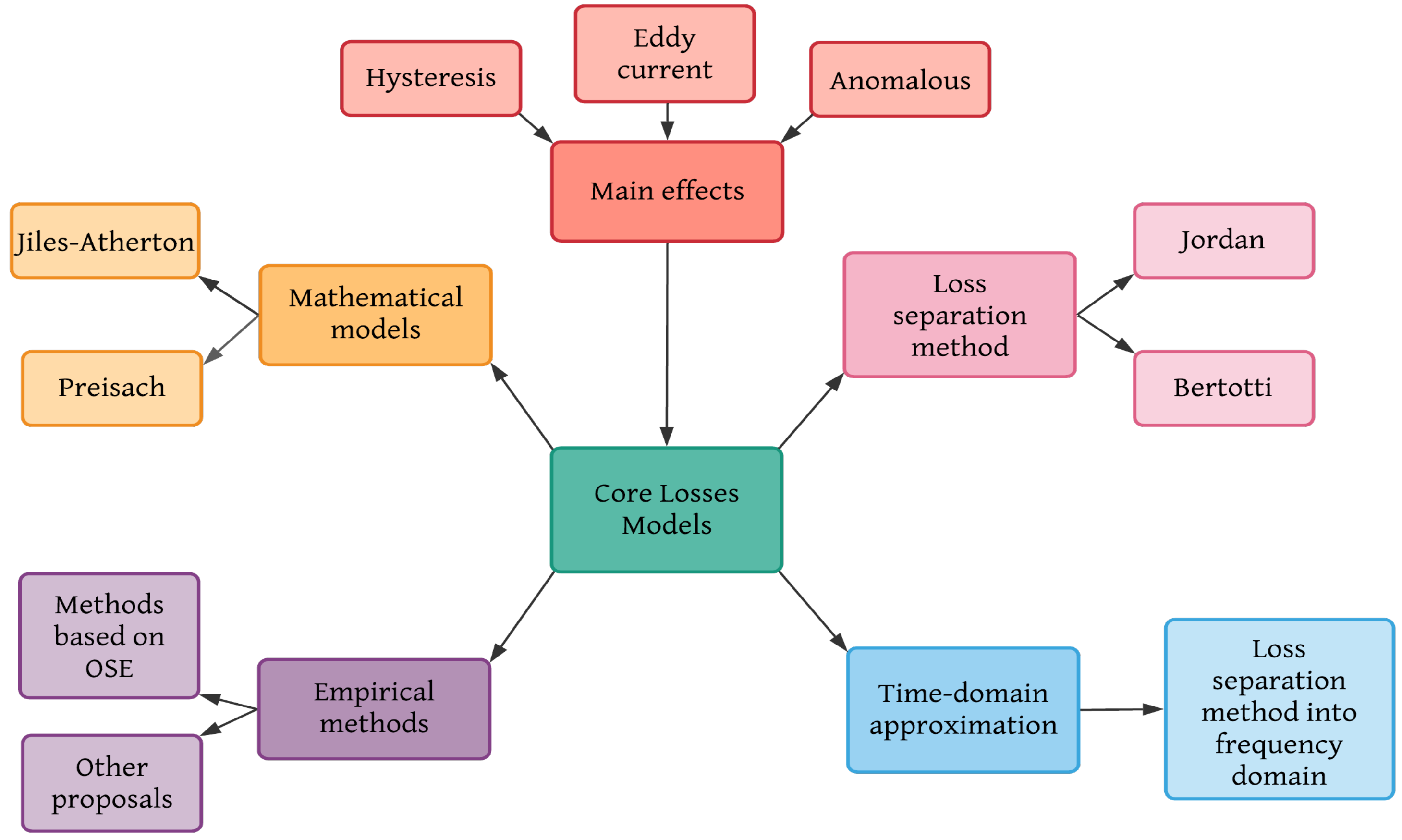
Figure 1. Classification of core losses methods.
4. Magnetic Components Design Process
In general, the design process of a magnetic component consists of four steps: design, simulate, implement, and evaluate.
The design step can completely follow the diagram, where the application specifications will determine the selection core material up to the copper losses, the core losses model, and the high-frequency effects according to [62][63].
It is worth to mention, that there are some intermediate steps, which are related to core physical and magnetic parameters such as the cross section of the core, section of the core, length of it, effective relative permeability, peak to peak density ripple, among others [64]. In the same way, choosing a gapped core (a core with a concentrated air gap) instead of a distributed air gap core will impact its behavior and parameters to calculate; for the first one, gap parameters as length are a priority. For the second one, permeability parameters will be taken into account [65].
As applications specifications as selection core material are fundamental to select or design a core losses model, both will establish the minimum parameters to calculate power losses.
The simulate step is the masterpiece to validate the magnetic component designed, but at the same time, it will be a problematic step if the designer is not careful; FEM software always will give a solution but does not mean that it is correct. In a general way, simulation steps can be subdivided into three parts: data analysis, finite element method, and simulation of applications.
From the design steps depending on the models selected to calculate power losses, core physical parameters, and data related to the windings, many formulas are involved, and sometimes some depend on others; software such as Mathcad® and Matlab® are of great help. Finite element method (FEM) is a big world, as it was explained in the section before. Once the magnetic component’s design is complete (windings and core parameters) and validated in FEM; the next step consists in exporting the final FEM design to software like Simulink® or Twin Builder®, PSIM®, to simulate it in a specific application and corroborate its correct performance [34][66][67][68][69].
The implementation step tests the simulated application through the interconnection of different sorts of software and platforms (MCU hardware, LabVIEW®, Typhoon HIL, among others) to simulate it with high fidelity, in similar conditions to real [70]. Typhoon in the loop (HIL) systems is a feasible example of this. The reader interested in magnetic component testing is referred to [71][72][73][74][75][76] and the references therein.
The last one is to evaluate, that is, physically build the magnetic component designed and tested in the steps before and implement it in a circuit. Technically speaking, the tests obtained in the implementation step must coincide with the physical circuit measurements with a minimal error percentage. If the magnetic component behavior is not satisfactory, the steps must be repeated, modifying the necessary parameters until the desired results are obtained.
5. Magnetic Devices and Miniaturization
Transportation, electrification, medical applications, micromachines, wireless communication and wireless charging are some areas demanding new technology to develop compact and high performance applications; and the manufacturing of low losses magnetic components is key [77].
Magnetic components exhibit design difficulties when power conversion systems require low power levels and high frequencies due to the nonlinear behavior of magnetic materials, thermal limits, and the exponential increase of losses under these conditions.
Core data and core losses models are critical to design magnetic components properly and select the size of magnetic devices. According to core selection material different procedures may be applied [78].
Miniaturization of magnetic components and micromachines are an interesting couple to develop and implement in biomedical devices and applications. In biomedical applications magnetism-based systems are widely utilized, for example, to know and measure human tissue and organs (such as magnetocardiography, magnetoneurography, magnetoencephalography, and magnetomyography) [79][80][81][82]. By 2021, the market of magnetic sensors will worth around $7.6 billion due to their attractive commercial purposes and new application areas [83]. However, the development of efficient magnetic technologies that are sensitive, inexpensive, biocompatible and miniaturized is still far away [84].
The miniaturization, feasibility and integration of magnetic sensors for biomagnetic signal detection have been in constant evolution in terms of size, sensing signals magnitude (pico-Tesla scale), and environment conditions. In magnetic sensors, the magnetic field is converted into measurable quantities as voltage and current [79]. Some examples of them are the thin-film magnetoelectric (ME) sensors, optically pumped magnetometers (OPM), superconducting quantum interference device (SQUID), flux gate sensors, giant magnetoimpedance (GMI) sensor, magnetic sensors based on the thin-film magnetoresistive (MR), and conventional superconducting coils.
In [85], a GMI miniaturized magnetic sensor fabricated with a Co-based amorphous by Micro-Electro-Mechanical System (MEMS) technology wire is described, achieving a size of
5.6 × 1.5 × 1.1 mm3 Co-based amorphous wire is selected for its high impedance change rate, increasing the sensitive of the GMI sensor, it is used to fabricated a pick-up coil of 200 turns and diameter of 200 μm.
A common problem in biomagnetic sensors is the noise at low frequencies, specifically between 10 and 100 Hz due to the small magnitude of measured signals. A set of bi-planar electromagnetic coils is a recent technique to cancelling the Earth’s noise nearby the magnetic sensors and improving their sensitivity [79].
Magnetic signal detection including portable and handled devices in the point-of-care testing (POCT) including mini magnetic induction coils and electromagnets to do the devices more portable, flexible and with high detection capabilities. In [86] several examples of these applications are described, where magnetic devices have dimensions in centimeters scale and those consider other POCT techniques for their favorable accuracy, high reliability, innovation and novelty, although their cost might increase.
Portable and small size, or even single handled devices that provide rapid and accurate detection have potential application of POCT [86]. Portable and wearable biosensors are the future of healthcare sensor technologies. Those have demonstrated their utility in disease diagnosis with accurate prediction. Their incorporation with mobile phones is known as digital health or mobile health, which promises reduce the frequency of clinical visits, prevent health problems and revolutionary the demand of micro and wearable sensors technology [87][88][89].
The emerge of microrobots and the use of a magnetic resonance imaging help to improve diagnostic capabilities by minimally invasive procedures. A microrobot is a robot on a microscale that can perform high-precision operations. Microrobots’ actuation system require input energy to act it, which usually requires special materials (soft and hard magnetic materials) or structural design (arrangement of coils) [90][91]. While the propulsion of microrobots, ferromagnetic cores and magnetic structures can be used to generate an image of many sites in the human body [92][93][94].
In [95], microcoils with a diameter < 1 mm are used to harvest electromagnetic energy wirelessly by inductive coupling in the on-board energy robots, achieving several milliwatts of power, capable of controlled motion and actuation with a maximum efficiency of 40%. This has been a recent development to controlled and powered remotely a system-engineered miniaturized robot (SEMER).
To increase the adaptability and robustness of robotic systems in challenging environments, and inter disciplinary research is needed, including material science, biology, control, among others [95]. Magnetic materials and magnetoelectric concepts of micro and nanorobots in magnetic applications are detailed in [96].
In this authors opinion the versatility, scalability, and flexibility of developing a power core loss model to analyze and allowing a better comprehension of the magnetic phenomena in ferromagnetic materials, will be the first step to the miniaturization of magnetic devices and power conversion systems at any scale [97][98].
Abbreviations
| B | Magnetic flux density | ||
| Bn |
Magnetic flux density of the nth harmonic |
||
| f | Fundamental frequency |
References
- Krishnan, K.M. Fundamentals and Applications of Magnetic Materials; Oxford University Press: Oxford, UK, 2016; p. 816.
- Cullity, B.; Graham, C. Soft magnetic materials. In Introduction to Magnetic Materials; John Wiley & Sons, Ltd.: Hoboken, NJ, USA, 2008; Chapter 13; pp. 439–476.
- Ulaby, F.T. Fundamentos de Aplicaciones en Electromagnetismo; Pearson: London, UK, 2007.
- Cheng, D. Fundamentos de Electromagnetismo para Ingeniería. Mexicana, A., Ed.; 1997; Available online: https://www.academia.edu/36682331/Fundamentos_de_Electromagnetismo_para_Ingenieria_David_K_Cheng (accessed on 24 February 2022).
- Coey, J.M.D. Magnetism and Magnetic Materials; Cambridge University Press: Cambridge, UK, 2010.
- Goldman, A. Handbook of Modern Ferromagnetic Materials; Springer: Boston, MA, USA, 1999.
- Gupta, K.; Gupta, N. Magnetic Materials: Types and Applications. In Advanced Electrical and Electronics Materials; John Wiley & Sons, Ltd.: Hoboken, NJ, USA, 2015; Chapter 12; pp. 423–448.
- Hitachi. Nanocrystalline Material Properties; Hitachi: Tokyo, Japan, 2019.
- County Council, K.; Richardson, A. Silver Wire Ring. 2017. . Available online: https://www.academia.edu/2306387/With_Dickinson_T_M_and_Richardson_A_Early_Anglo_Saxon_Eastry_Archaeological_Evidence_for_the_Beginnings_of_a_District_Centre_in_the_Kingdom_of_Kent_Anglo_Saxon_Studies_in_Archaeology_and_History_17 (accessed on 24 February 2022).
- Alisdojo. Detail of an Enamelled Litz Wire. 2011. . Available online: https://commons.wikimedia.org/wiki/File:Enamelled_litz_copper_wire.JPG (accessed on 24 February 2022).
- Magnetics. Powder Cores Properties; Magnetics: Pittsburgh, PA, USA, 2019.
- Laboratory, N.E.T. FINEMET Properties. 2018. Available online: https://www.hitachi-metals.co.jp/e/products/elec/tel/p02_21.html#:~:text=FINEMET%C2%AE%20has%20high%20saturation,and%20electronics%20devices%20as%20well (accessed on 24 February 2022).
- CATECH®. Amorphous and Nanocrystalline Core; CATECH: Singapore, 2022.
- Soon, H. Wire. 2017. . Available online: https://iopscience.iop.org/article/10.1088/1742-6596/871/1/012098/pdf (accessed on 24 February 2022).
- Aluminium Wire, 16 mm2. 2012. . Available online: https://ceb.lk/front_img/specifications/1540801489P.V_.C_._INSULATED_ALUMINIUM_SERVICE_MAIN_WIRE-FINISHED_PRODUCT_.pdf (accessed on 24 February 2022).
- County Council, K.; Richardson, A. Length of Gold Wire, Ringlemere. 2017. . Available online: https://www.sachsensymposion.org/wp-content/uploads/2012/04/68th-International-Sachsensymposion-Canterbury.pdf (accessed on 24 February 2022).
- SpinningSpark. Transformer Core. 2012. . Available online: https://commons.wikimedia.org/wiki/File:Transformer_winding_formats.jpg (accessed on 24 February 2022).
- TheDigitalArtist. coil-gd137ed32f-1920. 2015. . Available online: https://plato.stanford.edu/entries/digital-art/ (accessed on 24 February 2022).
- Fiorillo, F.; Bertotti, G.; Appino, C.; Pasquale, M. Soft magnetic materials. In Wiley Encyclopedia of Electrical and Electronics Engineering; American Cancer Society: Atlanta, GA, USA, 2016; pp. 1–42.
- Aguglia, D.; Neuhaus, M. Laminated magnetic materials losses analysis under non-sinusoidal flux waveforms in power electronics systems. In Proceedings of the 15th European Conference on Power Electronics and Applications (EPE), Lille, France, 2–6 September 2013; pp. 1–8.
- McLyman, C. Transformer and Inductor Design Handbook, 3rd ed.; Taylor & Francis: Abingdon-on-Thames, UK, 2004.
- Tsepelev, V.; Starodubtsev, Y.; Konashkov, V.; Belozerov, V. Thermomagnetic analysis of soft magnetic nanocrystalline alloys. J. Alloys Compd. 2017, 707, 210–213.
- Ouyang, G.; Chen, X.; Liang, Y.; Macziewski, C.; Cui, J. Review of Fe-6.5 wt% silicon steel-a promising soft magnetic material for sub-kHz application. J. Magn. Magn. Mater. 2019, 481, 234–250.
- Yuan, W.; Wang, Y.; Liu, D.; Deng, F.; Chen, Z. Impacts of inductor nonlinear characteristic in multi-converter microgrids: Modelling, analysis and mitigation. IEEE J. Emerg. Sel. Top. Power Electron. 2020, 8, 3333–3347.
- Kazimierczuk, M. High-Frequency Magnetic Components, 2nd ed.; John Wiley & Sons, Ltd.: Hoboken, NJ, USA, 2013.
- Tumanski, S. Handbook of Magnetic Measurements; Series in Sensors; CRC Press: Boca Raton, FL, USA, 2016.
- Goldman, A. Magnetic Components for Power Electronics; Springer: Berlin/Heidelberg, Germany, 2012.
- Wang, Y.; Calderon-Lopez, G.; Forsyth, A. Thermal management of compact nanocrystalline inductors for power dense converters. In Proceedings of the IEEE Applied Power Electronics Conference and Exposition (APEC), San Antonio, TX, USA, 4–8 March 2018; pp. 2696–2703.
- Conde, C.; Blázquez, J.; Conde, A. Nanocrystallization process of the Hitperm Fe-Co-Nb-B alloys. In Properties and Applications of Nanocrystalline Alloys from Amorphous Precursors; Idzikowski, B., Švec, P., Miglierini, M., Eds.; Springer: Dordrecht, The Netherlands, 2005; pp. 111–121.
- Tsepelev, V.S.; Starodubtsev, Y.N. Nanocrystalline soft magnetic iron-based materials from liquid state to ready product. Nanomaterials 2021, 11, 108.
- Lidow, A. Accelerating adoption of magnetic resonant wireless power based on the AirFuel, 2021. IEEE Wirel. Power Week. 2021. Available online: https://airfuel.org/wireless-power-week-2021-highlights/ (accessed on 24 February 2022).
- Jafari, M.; Malekjamshidi, Z.; Zhu, J. Copper loss analysis of a multiwinding high-frequency transformer for a magnetically-coupled residential microgrid. IEEE Trans. Ind. Appl. 2019, 55, 283–297.
- Slionnnnnn. The Prototype of the Balanced Twisted Winding CM Choke. 2017. . Available online: https://en.wikipedia.org/wiki/File:4ffffss123.jpg (accessed on 24 February 2022).
- Corti, F.; Reatti, A.; Lozito, G.M.; Cardelli, E.; Laudani, A. Influence of non-linearity in losses estimation of magnetic components for DC-DC converters. Energies 2021, 14, 6498.
- Zhu, F.; Yang, B. Power Transformer Design Practices; CRC Press: Boca Raton, FL, USA, 2021.
- Glisson, T. Introduction to Circuit Analysis and Design; Springer: Berlin/Heidelberg, Germany, 2011.
- Wang, W.; Nysveen, A.; Magnusson, N. The influence of multidirectional leakage flux on transformer core losses. J. Magn. Magn. Mater. 2021, 539, 168370.
- Kulkarni, S.; Khaparde, S. Transformer Engineering: Design, Technology, and Diagnostics, 2nd ed.; Taylor & Francis: Abingdon-on-Thames, UK, 2012.
- Tian, H.; Wei, Z.; Vaisambhayana, S.; Thevar, M.P.; Tripathi, A.; Kjær, P.C. Calculation and experimental validation on leakage inductance of a medium frequency transformer. In Proceedings of the IEEE 4th Southern Power Electronics Conference (SPEC), Singapore, 10–13 December 2018; pp. 1–6.
- Kothari, D.; Nagrath, I. Modern Power System Analysis; Tata McGraw-Hill Publishing Company: New York, NK, USA, 2003.
- Barg, S.; Alam, M.F.; Bertilsson, K. Optimization of high frequency magnetic devices with consideration of the effects of the magnetic material, the core geometry and the switching frequency. In Proceedings of the 22nd European Conference on Power Electronics and Applications (EPE’20 ECCE Europe), Lyon, France, 7–11 September 2020; pp. 1–8.
- Ouyang, Z. High Frequency Planar Magnetics for Power Converters; Presentation; ECPE Online Tutorial: Nuremberg, Germany, 2021.
- Barrios, E.L.; Ursúa, A.; Marroyo, L.; Sanchis, P. Analytical design methodology for Litz-wired high-frequency power transformers. IEEE Trans. Ind. Electron. 2015, 62, 2103–2113.
- Brighenti, L.L.; Martins, D.C.; Dos Santos, W.M. Study of magnetic core geometries for coupling systems through a magnetic bus. In Proceedings of the IEEE 10th International Symposium on Power Electronics for Distributed Generation Systems (PEDG), Xi’an, China, 3–6 June 2019; pp. 29–36.
- Rodriguez-Sotelo, D.; Rodriguez-Licea, M.A.; Soriano-Sanchez, A.G.; Espinosa-Calderon, A.; Perez-Pinal, F.J. Advanced ferromagnetic materials in power electronic converters: A state of the art. IEEE Access 2020, 8, 56238–56252.
- Detka, K.; Górecki, K. Influence of the size and shape of magnetic core on thermal parameters of the inductor. Energies 2020, 13, 3842.
- Jiandong, D.; Yang, L.; Hao, L. Research on ferromagnetic components J-A model—A review. In Proceedings of the International Conference on Power System Technology (POWERCON), Guangzhou, China, 6–8 November 2018; pp. 3288–3294.
- Saeed, S.; Georgious, R.; Garcia, J. Modeling of magnetic elements including losses-application to variable inductor. Energies 2020, 13, 1865.
- Ishikura, Y.; Imaoka, J.; Noah, M.; Yamamoto, M. Core loss evaluation in powder cores: A comparative comparison between electrical and calorimetric methods. In Proceedings of the International Power Electronics Conference (IPEC-Niigata 2018-ECCE Asia), Niigata, Japan, 20–24 May 2018; pp. 1087–1094.
- Hanif, A. Measurement of Core Losses in Toroidal Inductors with Different Magnetic Materials. Master’s Thesis, Tampere University of Technology, Tampere, Finland, 2017.
- Wang, Y. Modelling and Characterisation of Losses in Nanocrystalline Cores. Ph.D. Thesis, The University of Manchester, Manchester, UK, 2015.
- Yue, S.; Li, Y.; Yang, Q.; Yu, X.; Zhang, C. Comparative analysis of core loss calculation methods for magnetic materials under nonsinusoidal excitations. IEEE Trans. Magn. 2018, 54, 6300605.
- Bi, S. Charakterisieren und Modellieren der Ferromagnetischen Hysterese. Ph.D. Thesis, Friedrich-Alexander-Universität Erlangen-Nürnberg (FAU), Erlangen, Germany, 2014.
- Iniewski, K. Advanced Circuits for Emerging Technologies; Wiley: Hoboken, NJ, USA, 2012.
- Sudhoff, S. Power Magnetic Devices: A Multi-Objective Design Approach; IEEE Press Series on Power Engineering; Wiley: Hoboken, NJ, USA, 2014.
- Spaldin, N. Magnetic Materials: Fundamentals and Applications; Cambridge University Press: Cambridge, UK, 2010.
- Dong Tan, F.; Vollin, J.L.; Cuk, S.M. A practical approach for magnetic core-loss characterization. IEEE Trans. Power Electron. 1995, 10, 124–130.
- Fiorillo, F.; Mayergoyz, I. Characterization and Measurement of Magnetic Materials; Elsevier: Amsterdam, The Netherlands, 2004.
- O’Handley, R. Modern Magnetic Materials: Principles and Applications; Wiley: Hoboken, NJ, USA, 1999.
- Krings, A.; Soulard, J. Overview and comparison of iron loss models for electrical machines. J. Electr. Eng. Elektrotechnicky Cas. 2010, 10, 162–169.
- Haase, H. Forward Converter ATX PC Power Supply. 2013. . Available online: https://commons.wikimedia.org/wiki/File:Forward_Converter_ATX_PC_Power_Supply_IMG_1092.jpg (accessed on 24 February 2022).
- Hurley, W.G. Passives in Power Electroics: Magnetic Component Design and Simulation; Presentation; ECPE Online Tutorial: Nuremberg, Germany, 2021.
- Ionita, V.; Cazacu, E.; Petrescu, L. Effect of voltage harmonics on iron losses in magnetic cores with hysteresis. In Proceedings of the 2018 18th International Conference on Harmonics and Quality of Power (ICHQP), Ljubljana, Slovenia, 13–16 May 2018; pp. 1–5.
- Ruiz-Robles, D.; Figueroa-Barrera, C.; Moreno-Goytia, E.L.; Venegas-Rebollar, V. An experimental comparison of the effects of nanocrystalline core geometry on the performance and dispersion inductance of the MFTs applied in DC-DC converters. Electronics 2020, 9, 453.
- Jiang, C.; Li, X.; Ghosh, S.; Zhao, H.; Shen, Y.; Long, T. Nanocrystalline powder cores for high-power high-frequency applications. IEEE Trans. Power Electron. 2020, 35, 10821–10830.
- Islam, M.R.; Farrok, O.; Rahman, M.A.; Kiran, M.R.; Muttaqi, K.M.; Sutanto, D. Design and characterisation of advanced magnetic material-based core for isolated power converters used in wave energy generation systems. IET Electr. Power Appl. 2020, 14, 733–741.
- Bolsi, P.C.; Sartori, H.C.; Pinheiro, J.R. Comparison of core technologies applied to power inductors. In Proceedings of the 13th IEEE International Conference on Industry Applications (INDUSCON), Sao Paulo, Brazil, 12–14 November 2018; pp. 1100–1106.
- Imaoka, J.; Yu-Hsin, W.; Shigematsu, K.; Aoki, T.; Noah, M.; Yamamoto, M. Effects of high-frequency operation on magnetic components in power converters. In Proceedings of the IEEE 12th Energy Conversion Congress Exposition—Asia (ECCE-Asia), Singapore, 24–27 May 2021; pp. 978–984.
- Delgado, A.; Oliver, J.A.; Cobos, J.A.; Rodriguez-Moreno, J. Macroscopic modeling of magnetic microwires for finite element simulations of inductive components. IEEE Trans. Power Electron. 2020, 35, 8452–8459.
- Abourida, S.; Dufour, C.; Belanger, J.; Yamada, T.; Arasawa, T. Hardware-in-the-loop simulation of finite-element based motor drives with RT-LAB and JMAG. In Proceedings of the IEEE International Symposium on Industrial Electronics, Montreal, QC, Canada, 9–13 July 2006; Volume 3, pp. 2462–2466.
- Bjørheim, F.; Siriwardane, S.C.; Pavlou, D. A review of fatigue damage detection and measurement techniques. Int. J. Fatigue 2022, 154, 106556.
- Faba, A.; Quondam Antonio, S. An Overview of Non-Destructive Testing of Goss Texture in Grain-Oriented Magnetic Steels. Mathematics 2021, 9, 1539.
- Ibrahim, M.; Singh, S.; Barman, D.; Bernier, F.; Lamarre, J.M.; Grenier, S.; Pillay, P. Selection of Soft Magnetic Composite Material for Electrical Machines using 3D FEA Simulations. In Proceedings of the 2021 IEEE Energy Conversion Congress and Exposition (ECCE), Vancouver, BC, Canada, 10–14 October 2021; pp. 3860–3865.
- Xie, S.; Zhang, L.; Zhao, Y.; Wang, X.; Kong, Y.; Ma, Q.; Chen, Z.; Uchimoto, T.; Takagi, T. Features extraction and discussion in a novel frequency-band-selecting pulsed eddy current testing method for the detection of a certain depth range of defects. NDT E Int. 2020, 111, 102211.
- Li, E.; Chen, Y.; Chen, X.; Wu, J. Defect Width Assessment Based on the Near-Field Magnetic Flux Leakage Method. Sensors 2021, 21, 5424.
- Galluzzi, R.; Amati, N.; Tonoli, A. Modeling, Design, and Validation of Magnetic Hysteresis Motors. IEEE Trans. Ind. Electron. 2020, 67, 1171–1179.
- Kang, S.G.; Song, M.S.; Kim, J.W.; Lee, J.W.; Kim, J. Near-Field Communication in Biomedical Applications. Sensors 2021, 21, 703.
- Calderon-Lopez, G.; Todd, R.; Forsyth, A.J.; Wang, J.; Wang, W.; Yuan, X.; Aldhaher, S.; Kwan, C.; Yates, D.; Mitcheson, P.D. Towards Lightweight Magnetic Components for Converters with Wide-bandgap Devices. In Proceedings of the 2020 IEEE 9th International Power Electronics and Motion Control Conference (IPEMC2020-ECCE Asia), Nanjing, China, 29 November–2 December 2020; pp. 3149–3155.
- Zuo, S.; Heidari, H.; Farina, D.; Nazarpour, K. Miniaturized Magnetic Sensors for Implantable Magnetomyography. Adv. Mater. Technol. 2020, 5, 2000185.
- Trohman, R.G.; Huang, H.D.; Sharma, P.S. The Miniaturization of Cardiac Implantable Electronic Devices: Advances in Diagnostic and Therapeutic Modalities. Micromachines 2019, 10, 633.
- Murzin, D.; Mapps, D.J.; Levada, K.; Belyaev, V.; Omelyanchik, A.; Panina, L.; Rodionova, V. Ultrasensitive Magnetic Field Sensors for Biomedical Applications. Sensors 2020, 20, 1569.
- Jeon, S.; Park, S.H.; Kim, E.; Kim, J.y.; Kim, S.W.; Choi, H. A Magnetically Powered Stem Cell-Based Microrobot for Minimally Invasive Stem Cell Delivery via the Intranasal Pathway in a Mouse Brain. Adv. Healthc. Mater. 2021, 10, 2100801.
- Khan, M.A.; Sun, J.; Li, B.; Przybysz, A.; Kosel, J. Magnetic sensors-A review and recent technologies. Eng. Res. Express 2021, 3, 022005.
- Sharma, A.; Jain, V.; Gupta, D.; Babbar, A. A Review Study on Miniaturization: A Boon or Curse. In Advanced Manufacturing and Processing Technology; CRC Press: Boca Raton, FL, USA, 2020; pp. 111–131.
- Chen, J.; Li, J.; Li, Y.; Chen, Y.; Xu, L. Design and Fabrication of a Miniaturized GMI Magnetic Sensor Based on Amorphous Wire by MEMS Technology. Sensors 2018, 18, 732.
- Yang, J.; Wang, K.; Xu, H.; Yan, W.; Jin, Q.; Cui, D. Detection platforms for point-of-care testing based on colorimetric, luminescent and magnetic assays: A review. Talanta 2019, 202, 96–110.
- Tu, J.; Torrente-Rodríguez, R.M.; Wang, M.; Gao, W. The Era of Digital Health: A Review of Portable and Wearable Affinity Biosensors. Adv. Funct. Mater. 2020, 30, 1906713.
- Purohit, B.; Kumar, A.; Mahato, K.; Chandra, P. Smartphone-assisted personalized diagnostic devices and wearable sensors. Curr. Opin. Biomed. Eng. 2020, 13, 42–50.
- Dinis, H.; Mendes, P. A comprehensive review of powering methods used in state-of-the-art miniaturized implantable electronic devices. Biosens. Bioelectron. 2021, 172, 112781.
- Sitti, M.; Wiersma, D.S. Pros and Cons: Magnetic versus Optical Microrobots. Adv. Mater. 2020, 32, 1906766.
- Zhou, H.; Mayorga-Martinez, C.C.; Pané, S.; Zhang, L.; Pumera, M. Magnetically Driven Micro and Nanorobots. Chem. Rev. 2021, 121, 4999–5041.
- Mathieu, J.B.; Beaudoin, G.; Martel, S. Method of propulsion of a ferromagnetic core in the cardiovascular system through magnetic gradients generated by an MRI system. IEEE Trans. Biomed. Eng. 2006, 53, 292–299.
- Vitol, E.A.; Novosad, V.; Rozhkova, E.A. Microfabricated magnetic structures for future medicine: From sensors to cell actuators. Nanomedicine 2012, 7, 1611–1624.
- Li, Z.; Li, C.; Dong, L.; Zhao, J. A Review of Microrobot’s System: Towards System Integration for Autonomous Actuation In Vivo. Micromachines 2021, 12, 1249.
- Bandari, V.K.; Schmidt, O.G. System-Engineered Miniaturized Robots: From Structure to Intelligence. Adv. Intell. Syst. 2021, 3, 2000284.
- Xu, K.; Xu, S.; Wei, F. Recent progress in magnetic applications for micro- and nanorobots. Beilstein J. Nanotechnol. 2021, 12, 744–755.
- Hein, H.; Li, Y.; Yue, S.; Sun, H. Core Losses Analysis for Soft Magnetic Materials under SPWM Excitations. Int. J. Electromagn. Appl. 2020, 10, 1–6.
- Sundaria, R.; Nair, D.G.; Lehikoinen, A.; Arkkio, A.; Belahcen, A. Effect of Laser Cutting on Core Losses in Electrical Machines—Measurements and Modeling. IEEE Trans. Ind. Electron. 2020, 67, 7354–7363.
More
Information
Subjects:
Engineering, Electrical & Electronic
Contributors
MDPI registered users' name will be linked to their SciProfiles pages. To register with us, please refer to https://encyclopedia.pub/register
:
View Times:
1.8K
Revisions:
3 times
(View History)
Update Date:
07 Apr 2022
Table of Contents


Notice
You are not a member of the advisory board for this topic. If you want to update advisory board member profile, please contact office@encyclopedia.pub.
OK
Confirm
Only members of the Encyclopedia advisory board for this topic are allowed to note entries. Would you like to become an advisory board member of the Encyclopedia?
Yes
No
${ textCharacter }/${ maxCharacter }
Submit
Cancel
Back
Comments
${ item }
|
${ item.createdUser.fullName }
${ item.createdAt }
${ item.vote }
${ item.reply }
Delete
${ reply.createdUser.fullName }
${ reply.createdAt }
${ reply.vote }
Delete
There is no reply to this comment~
${ item.replyTextCharacter }/${ item.replyMaxCharacter }
Submit
Cancel
More
No more~
There is no comment~
${ textCharacter }/${ maxCharacter }
Submit
Cancel
${ selectedItem.replyTextCharacter }/${ selectedItem.replyMaxCharacter }
Submit
Cancel
Confirm
Are you sure to Delete?
Yes
No