 +1 credit
| Version | Summary | Created by | Modification | Content Size | Created at | Operation |
|---|---|---|---|---|---|---|
| 1 | Asset Kabyshev | -- | 4105 | 2022-04-06 11:26:24 | | | |
| 2 | Rita Xu | Meta information modification | 4105 | 2022-04-06 11:34:01 | | | | |
| 3 | Rita Xu | Meta information modification | 4105 | 2022-04-08 05:31:08 | | | | |
| 4 | Alexey Nikonov | + 3422 word(s) | 7527 | 2022-04-12 16:34:31 | | | | |
| 5 | Rita Xu | Meta information modification | 7527 | 2022-04-13 10:26:21 | | |
Video Upload Options
Solid oxide fuel cells (SOFC) are promising, environmentally friendly energy sources. Many works are devoted to the study of materials, individual aspects of SOFC operation, and the development of devices based on them. This entry attempts to cover and structure the entire spectrum of SOFC concepts and designs that currently exist.
1. Introduction
2. Classification of SOFC
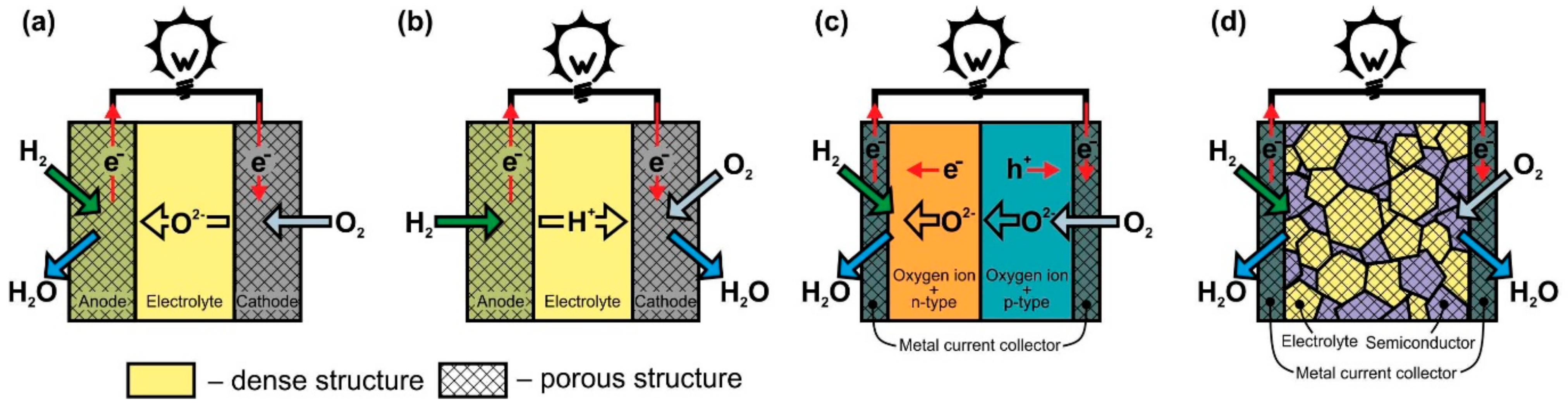
2.1. Classification according to the Presence/Absence of Electrolyte

| SOFC Type | Advantages | Disadvantages |
|---|---|---|
| O-SOFC | Well-studied There are industrial devices Potential for internal reforming |
Complexity of fabrication Limited selection of materials Low conductivity electrolyte High operating temperatures result in higher thermomechanical stresses and more significant degradation |
| H-SOFC | Higher conductive electrolyte Low operating temperatures suggest less thermomechanical stress and less degradation No fuel dilution with reaction products (H2O) |
More research on electrolyte and electrode materials are required Complexity of fabrication Internal reforming is questionable |
| DLFC | Simplicity of fabrication The problem of thermomechanical matching of cell materials is alleviated Wide selection of materials |
Poorly studied No internal reforming |
| SLFC | Simplicity of fabrication No problem with thermomechanical matching of cell materials Wide selection of materials |
Poorly studied Internal reforming is questionable |
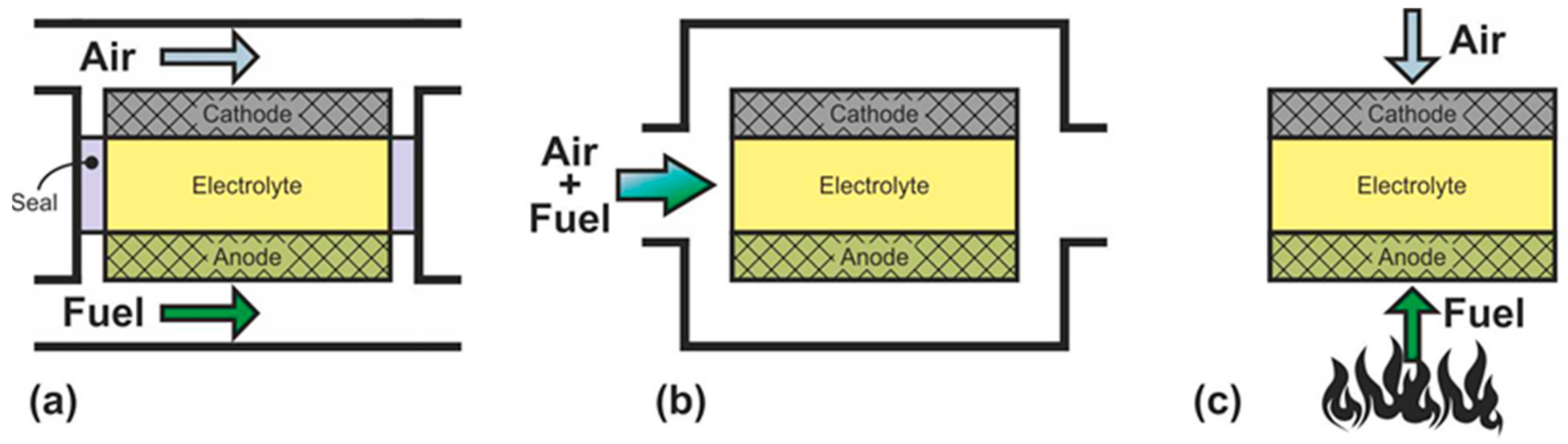
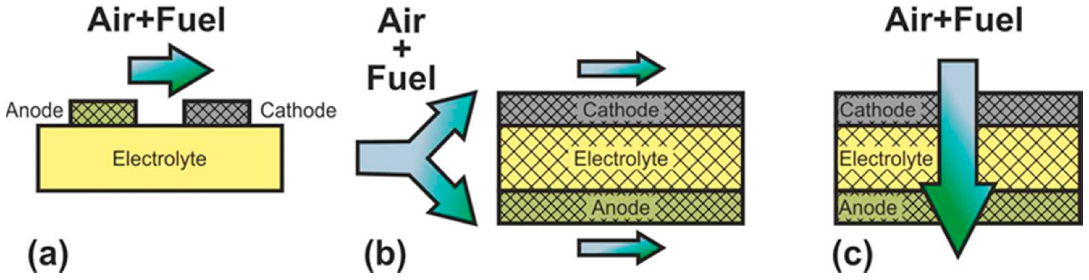
2.2. Classification according to the Gas Spaces Separation
| SOFC Type | Advantages | Disadvantages |
|---|---|---|
| DC-SOFC | Well-studied There are industrial devices High efficiency High level of fuel utilization Fire and explosion safety |
Complexity of fabrication Matching of thermal expansion of cell materials are required Slow start up |
| SC-SOFC | Simplicity of fabrication Simplified use of hydrocarbons as fuel High resistance to thermomechanical stress |
More selective electrodes are required Low efficiency Low level of fuel utilization Flammable and explosive Coking of electrodes |
| DF-SOFC | Simplicity of fabrication Simplified use of hydrocarbons as fuel Potential for quick start up |
More selective electrodes are required Low efficiency Low level of fuel utilization High thermomechanical stress Coking of electrodes |
2.3. Classification according to Operating Temperature
2.4. Classification according to Support Types
SOFC according to supporting component are usually divided into two large groups: self-supporting and external-supporting [5]. In a self-supporting SOFC, one of the components of the fuel cell (electrolyte, anode, or cathode) is the supporting element. In external-supporting SOFC, the supporting element is a porous inert substrate or a metal interconnect. Note that, due to the inherent feature of the design, the supporting substrate of the SC-SOFC can be gas-tight. SOFC schemes with different supporting components are shown in Figure 4.

Figure 4. Different types of cell support architectures for SOFC.
The advantages and disadvantages of SOFC with different supporting components are presented in Table 3 [5].
Table 3. Features of SOFC with the different supporting components.
| SOFC Type | Advantages | Disadvantages |
|---|---|---|
| Self-supporting | ||
| ES SOFC | Relatively strong structural support from dense electrolyte Less susceptible to failure due to anode reoxidation (Ni/YSZ anode) and cathode reduction (LSM cathode) |
Higher resistance due to low electrolyte conductivity Higher operating temperatures required to minimize electrolyte ohmic losses |
| AS SOFC | Highly conductive anode Lower operating temperature via use of thin electrolytes |
Potential anode reoxidation Mass transport limitation due to thick anodes |
| CS SOFC | No oxidation issues but potential cathode reduction Lower operating temperature via use of thin electrolyte |
Lower conductivity Mass transport limitation due to thick cathodes |
| External-supporting | ||
| SS SOFC | Thin cell components for lower operating temperature Potential for use of non-cell material for support to improve properties |
Increased complexity due to addition of new materials Possibility of formation of discontinuous layers on a porous substrate |
| MS SOFC | Thin cell components for lower operating temperature Stronger structures from metallic interconnects |
Interconnect oxidation Flowfield design limitation due to cell support requirement |
The supporting component in the overwhelming majority of the first SOFC was an electrolyte, and its thickness was about 0.2 mm [3][4]. The electrolyte-supported (ES) structure has relatively high strength and therefore has a low probability of mechanical failure, including due to re-oxidation of cermet anode based on Ni. However, the supporting electrolyte layer makes a significant contribution to the internal resistance of the SOFC. Since the conductivity of electrolytes has an exponential dependence on temperature [13], operating temperatures above 800 °C are required to achieve high specific power. Nevertheless, even now, the electrolyte supported design is popular among SOFC manufacturers [66][67][68].
The above-described tendency towards a decrease of the SOFC operating temperature resulted in the need to reduce the electrolyte thickness and transfer the function of the mechanical support to another component. The most widespread at present is the anode-supported (AS) structure of SOFC [69][70][71][72][73], which allows achieving high specific power at temperatures below 800 °C due to the thin electrolyte layer and high conductivity of the Ni-based anode [18]. In addition, this design is cheaper, because the NiO cost is lower than that of electrolyte and cathode materials. However, a significant drawback of the AS design is the possibility of anode re-oxidation, which is accompanied by a volume change of nickel by 41% [16] that can cause mechanical stresses and cell failure. Another problem of electrode supported designs is the limitation of the transfer of gas reagents through the thick, porous layer to the three-phase boundary, which can degrade the characteristics of the cell. In the anode supported structure, this problem is less acute than in the cathode supported (CS) one due to the already mentioned volumetric change of nickel during reduction. Moreover, the conductivity of cathode materials is lower than that of cermet anodes [74], which results in larger internal losses and, accordingly, to a lower specific power of CS SOFC in comparison with AS SOFC. The advantages of the cathode-supported structure include the phase stability of the supporting element (no oxidation–reduction cycles) and low ohmic losses on a thin electrolyte layer. CS SOFCs are not widely used, although this design was used to create the first kW-class generators developed by Simence/Westinghose [75]. It should be noted that the operating temperatures of industrial generators based on CS SOFC were above 900 °C.
The inert substrate-supported (SS) design allows the formation of thin electrolyte and electrode layers. This has to assistant in reducing the operating temperature and reaching of the high specific power of SOFC. Herewith, the supporting substrate can be made of a cheap material that is not usually used in the SOFC. In addition, the supporting substrate can be used as a carrier for a catalyst, allowing the conversion of hydrocarbon fuel into syngas [76]. On the other hand, the introduction of additional material into the SOFC composition increases the complexity of its design and manufacturing technology. Discontinuity of thin functional layers, which is very likely when they are formed on a porous substrate, can result in fuel cell failure. Despite these issues, industrial plants based on SS SOFC have been implemented [77][78] with operating temperatures above 900 °C.
The metal-supported (MS) design is attracting interest because of not only the low operating temperatures and potentially high specific power obtained by thin functional layers but also the high strength and electronic conductivity of the supporting component. However, the development of a technology of MS SOFC fabrication is not an easy task. A high sintering temperature is required for the formation of ceramic materials, while the metal substrate must not be overheated. Other serious problems of this design are the corrosion of the metal substrate under the SOFC operating conditions and the complexity in sealing operations. Advances in the development of interconnect supported SOFC are presented in [79][80]. The target operating temperatures of the MS SOFC are below 800 °C, but there are data on their testing at 850 °C [79].
The overwhelming majority of studies of H-SOFC are carried out on cells having an anode supported construction, which allows obtaining the highest power [27][63][81][82]. Only a few works were performed on cells with a supporting electrolyte [83] and supporting metal [84][85]. All studies of FEFC are currently performed on button cells, which can conditionally be classified as an electrolyte-supported design since the functional layer has a thickness of about 0.5-1 mm. The electrolyte- and anode-supported designs are manly used for DF-SOFC fabrication. A comparison of these two designs carried out in [64] showed that the maximum specific power of AS DF-SOFC (~ 475 mW∙cm−2) is almost four times higher than that of ES DF-SOFC (~ 121 mW∙cm−2). However, there are a few works are devoted to the development of metal supported DF-SOFC [65][86]. In Ref. [65], the peak specific power of 633 mW cm−2 was achieved on laboratory samples of MS DF-SOFC, whereas the specific power of the stack prototype tested on a commercial camping stove reached only 156 mW cm−2 [86], which is close to the one of ES DF-SOFC. Mostly, electrolytes and anodes are used as supporting components in SC-SOFC too [7][87][88]. In the single work [89] devoted to cathode-supported SC-SOFC, the peak specific power of only 9 mW∙cm−2 was obtained, whereas in AS SC-SOFC, power values of the order of 200–400 mW∙cm−2 are achieved [87][88]. A recent numerical simulation [90] has shown that the characteristics of a cathode-supported SC-SOFC should be less than those of an anode-supported SC-SOFC due to the difficulty of oxygen passing through the cathode layer to the reaction zone. The attempt of SC-SOFC forming on supporting dense substrates of MgO and stainless steel, which can be considered a supporting interconnect, was made in [91]. However, the internal resistance of the cells was very high. A numerical estimate of the residence time of the gas mixture in the cell has demonstrated that a structure with a supporting dense substrate for SC-SOFC is impractical [46]. No works describing SC-SOFC with a supporting porous substrate were found.
2.5. Classification according to Cell Design
Different geometric shapes of SOFC will be considered at the example of dual-chamber O-SOFC, since this group of fuel cells has the largest number of design options. Discussion of forms of other SOFC types will be carried out based on O-SOFC designs.
In accordance with the design, SOFC can be divided into planar, tubular, flat-tubular, and monolithic (Figure 5).
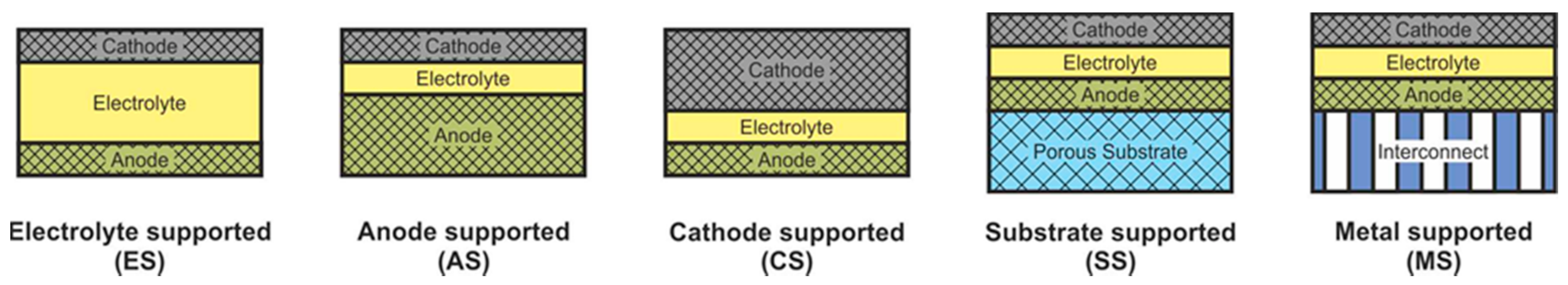
Figure 5. Schematics of (a) planar, (b) tubular, (c) flat-tube, and (d) monolithic SOFC.
The planar design (Figure 5a) is the most common due to the ease of manufacturing cells and assembling them in a stack, relatively low cost, and high specific volumetric power achieved by close packing of cells and low ohmic losses on interconnects. The disadvantages of the planar design are the difficulty in forming a hermetic seal between the anode and cathode chambers at stack assembly, as well as low resistance to thermal stress. An anode is most often the supporting elements of planar SOFC, but an electrolyte is also a common support. Examples of commercial applications of AS and ES planar SOFC are presented in [55][67]. Planar SOFC with supporting metal are also used in kW class generators [92], whereas the research and development of CS and SS planar cells are carried out at the laboratory level (see, for example, [93][94]).
The tubular SOFC design (Figure 5b) ranks second in popularity [95], although the first stacks were assembled on tubular cells [3][4]. Its advantages include ease of sealing, as well as higher mechanical strength and higher resistance to thermal stress due to the symmetric circular geometry. On the other hand, tubular SOFC have a lower specific volumetric power than planar cells due to less dense packing and larger internal losses associated with long paths of connecting cells in a stack. Moreover, the manufacturing process of the tubular cells is more expensive. Today, as well as for the planar cells, the supporting anode design is the most widespread architecture of tubular SOFC [72], having displaced the cathode-supported design from the leading position. Although, as already mentioned, the first large stacks were assembled on tubular CS SOFC [75]. The tubular design with supporting porous substrate has also been commercially implemented [78], whereas there are few works on ES and IS tubular cells [96][97].
The flat-tube SOFC design (Figure 5c) is essentially a hybrid of planar and tubular ones and it is elaborated to combine the advantages of both SOFC types. In flat-tube SOFC, the sealing is carried out more easily than in a planar design, and the simplicity of assembling cells to a stack is preserved. At the same time, the specific volumetric power of the flat-tube design is higher than that of a tubular one, whereas high resistance to thermal stress is continued. However, the manufacture of flat-tube SOFC should be more complicated and expensive than of planar cells. As the supporting element for a flat-tube design, a cathode (we consider the DELTA design as flat-tube one) [75], an anode [98][99], and a porous substrate [100] are used. A detailed description of materials, fabrication methods, and characteristics of flat-tube SOFC can be found in a recent review [101].
The scheme of a monolithic SOFC design is shown in Figure 5d. It is necessary to clarify that, in works [4][5], where the classification by design was performed jointly for cells and stacks, the term “monolithic design” has a different meaning than in [3]. In Ref. [3], it was believed that the basis of a monolithic fuel cell is a supporting electrolyte with a system of gas channels on the walls of which electrodes are applied (Figure 5d). The electrodes of adjacent channels have opposite signs; therefore, such a monolithic SOFC can be considered a stack of parallel-connected cells. In Refs. [4][5], a monolithic design was meant as a stack assembled from several series-connected corrugated cells that formed gas channels (Figure 6a). In this work, we will adhere to the terminology of [3], since cells and not stacks are classified. In addition, the so-called honeycomb SOFC (Figure 6b) [102][103], which are often distinguished by a special design [60], correspond to the taken definition of a monolithic design. The monolithic design advantages are high thermomechanical strength and a quite high specific volumetric power. However, this design is troublesome to manufacture and has difficulties in sealing and organizing current collectors. Perhaps this is the reason for the small number of works devoted to monolithic SOFC. All investigated monolithic SOFCs had a self-supporting structure, with a supporting electrolyte [102][104], a cathode [103], and an anode [105]. A metal interconnect can be used as a supporting element for a monolithic SOFC, but this will further complicate the fabrication. Applying a supporting porous substrate is apparently impossible without changing the concept of a monolithic SOFC, since the internal contact between adjacent channels will be broken.
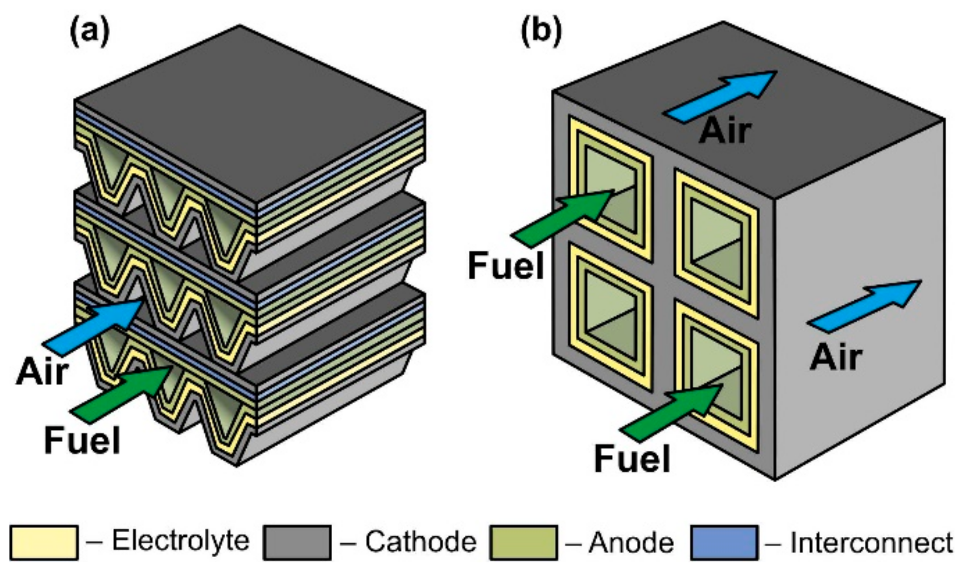
Figure 6. Schematics of (a) monolithic stack and (b) cathode-supported honeycomb SOFC.
Table 4 summarizes the advantages and disadvantages of the four main SOFC designs.
Table 4. Features of the different SOFC designs.
| SOFC Type | Advantages | Disadvantages |
|---|---|---|
| Planar | High power density Simplicity of stack assembly |
Low resistivity of thermomechanical stress Difficulties with sealing |
| Tubular | The resistivity of thermomechanical stress Sealing is simpler than that of planar SOFC |
Low power density High internal resistance |
| Flat-tube | The resistivity of thermomechanical stress Simplicity of stack assembly |
Complexity of fabrication of single cell High internal resistance |
| Monolithic | Sufficiently high power density High thermomechanical strength High durability |
Complexity of fabrication Difficulties with the formation of the current contacts Difficulties with sealing |
Among planar and tubular SOFC, microplanar and microtubular SOFC are distinguished, the development of which was carried out with an eye to mobile applications. The accentuation of these designs into separate groups is associated not only with the size of the fuel cells but with the features that arise when the size is reduced.
At the initial development stage of the concept of microplanar SOFC, these cells were usually called simply micro-SOFC [106], whereas now, they are commonly marked to as thin-film SOFC (TF-SOFC) [107][108]. In FT-SOFC, in contrast to large planar cells, the electrolyte layer thickness does not exceed 1 μm, which makes it possible to greatly reduce the operating temperature. The small electrolyte thickness is achieved due to the fact that the electrochemical part of the TF-SOFC is formed on the supporting substrate (Figure 7). There are two configurations of TF-SOFC: free-standing (Figure 7a) and porous substrate supported (Figure 7b).

Figure 7. Schematics of (a) free-standing FT-SOFC and (b) porous substrate supported FT-SOFC.
In free-standing TF-SOFC, an anode–electrolyte–cathode structure is formed over a hole in an inert material substrate (such as a silicon wafer). The main advantage of this structure is the use of very thin electrolytes with a thickness of tens of nanometres [108][109][110] that allows a reduction in the operating temperatures of TF-SOFCs to 300–500 °C. The highest peak power of free-standing TF-SOFCs of 1.3 W∙cm−2 at 450 °C [109] was achieved due to the combined effect of using a 60 nm-thick electrolyte and an increased effective area formed due to the three-dimensional architecture of the cell. However, in most works, the peak power is very modest, averaging 200–400 mW∙cm–2 [106][108]. In addition, free-standing TF-SOFC have a number of disadvantages: the warping of films during fabrication can result in to cracking; the low mechanical strength of the cathode–electrolyte–anode structure; the small active area of a single cell; manufacturing complexity; and the problem of scaling. Apparently, these drawbacks mean that this type of SOFC is practically not being developed now, although the work [111] proposes a manufacturing method of free-standing metal-supported TF-SOFC. Unfortunately, the cell characteristics are not given.
The fabrication of porous substrate supported TF-SOFCs is much simpler than that of free-standing TF-SOFC and consists of the serial formation of electrode and electrolyte layers on a substrate. The main technical issue at porous substrate supported TF-SOFC fabrication is to avoid the formation of defects in thin functional layers when they are deposited on a rough surface of the substrate. Therefore, material of the substrate is usually either a NiO-based composite, the porosity of which is formed/increased upon nickel reduction [106][108][112][113] or nanostructured anodized aluminum oxide (AAO) [106][108][114]. There are a number of works devoted to the development of metal supported TF-SOFC [115][116]. The values of specific power of porous substrate supported TF-SOFCs vary greatly in the literature, since the cells differ not only in the thickness of the electrolyte but also in the electrode materials. Most often, Pt is used as an electrode due to its low operating temperatures [106][110].
From a classification point of view, a free-standing TF-SOFC is SS SOFC design and a porous substrate supported TF-SOFC can be AS, SS, and MS SOFC depending on the substrate material.
Microtubular SOFC are tubular cells, the outer diameter of which is less than 3 mm. This results in a higher specific volumetric power of the stack and a significant increase in thermal shock resistance [117][118]. Increased thermomechanical characteristics of microtubular SOFC ensure quick start-up and high resistance to thermal cycling. The disadvantages of microtubular SOFC are mainly related to their being assembled in a stack: 1) construction issues at the organization of the current collection and connecting individual cells with each other [119] and 2) sealing of the stack [120]. Nevertheless, in the last decade, microtubular SOFC, due to their advantages, have attracted more attention than standard tubular cells [95][118]. The most common supporting element for microtubular SOFC as well as for tubular cells is an anode [121][122]. Microtubular SOFC with other supporting elements are also researched but there are much fewer works [123][124][125][126]. In addition, nanotube SOFC with an outer diameter of less than 500 nm have been fabricated; however, the obtained specific power was very low (1.3 μW∙cm−2 at 550 °C) [127].
Currently, almost all studies of mixed-reactant fuel cells (DF-SOFC and SC-SOFC) have been carried out on button cells. There are only a few works on the use of microtubes to investigate SOFC in a single-chamber regime [128]. H-SOFCs are also studied mainly in the form of button cells [26][27]; however, there are several works to obtain sufficiently large anode supported planar cells [129][130]. In addition, AS H-SOFC were fabricated in tubular [131][132], thin film [133], and microtubular [63][134][135] designs.
3. Separate Designs and Concepts of SOFC
Several separated SOFC designs and concepts which do not mention earlier are presented in the literature. These types of SOFC will be briefly considered, and their place in the proposed classification will be defined.
Sometimes, together with flat-tube and honeycomb SOFC, such designs as segmented-in-series or integrated planar SOFC and cone-shaped SOFC are discussed (Figure 8) [60]. Short current collectors inherent in these designs allow reducing the weight and cost of a fuel cell as well as improving its performance by low ohmic losses associated with the connection of the cells with each other. However, it must be emphasized that this is not some new type of separate cell design but a technique for connecting cells into a stack. The cone-shaped cells are a kind of tubular SOFC, whereas the segmented-in-series design was fabricated in both flat [77] and tubular [78] geometries.
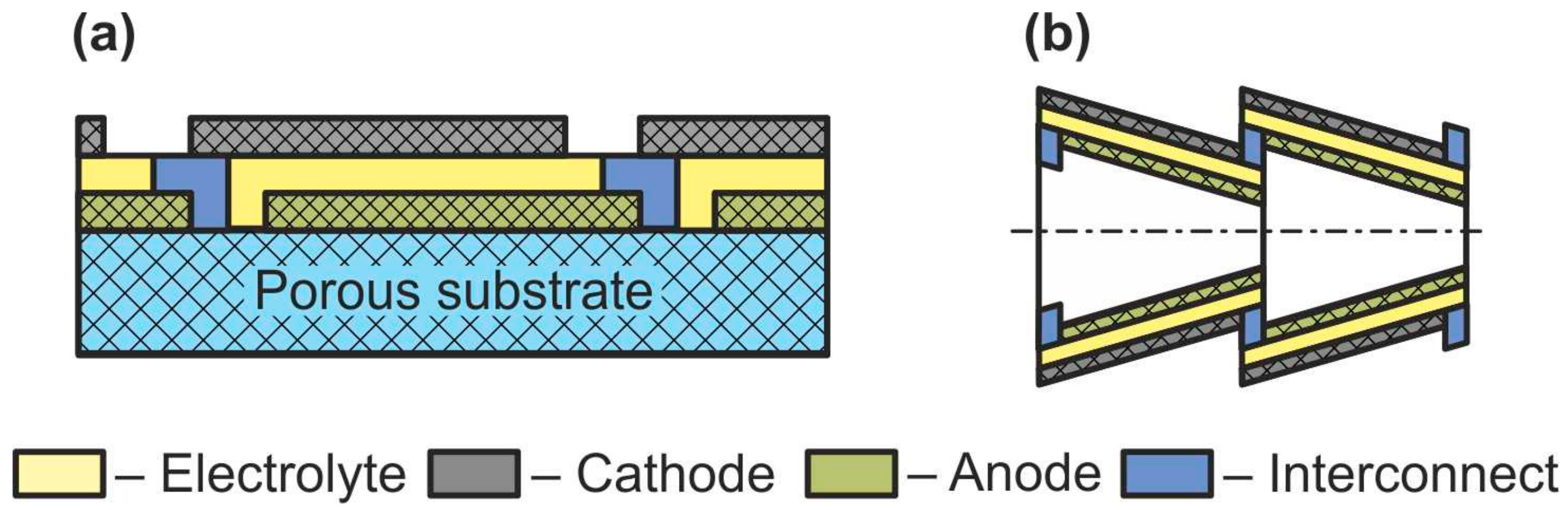
Figure 8. Schematics of (a) segmented-in-series SOFC and (b) cone-shaped SOFC.
The concept of symmetric SOFC (SSOFC) is to replace different electrode materials (anodic and cathodic) of conventional SOFC on one material [136]. This simplifies and reduces the cost of fabricating fuel cells, since both electrodes can be fired in one thermal cycle. In addition, the use of the same material for the anode and cathode diminishes the problems of thermomechanical compatibility of SOFC components by the formation of the same electrode–electrolyte boundaries. Another advantage of the symmetric SOFC concept is the ability to solve the issues associated with sulfur poisoning and carbon deposition by changing the direction of gas flows to oxidize these substances. Any design of a dual-chamber SOFC is suitable for the implementation of SSOFC concept, since the term “symmetric” means the same electrode materials and not the configuration of the cell itself. However, mixed-reactant SOFC with identical electrodes will not function, since it is impossible for one material to have selectivity to different reactions. The development of an electrode material that must simultaneously satisfy all the requirements for cathode and anode of SOFC is an obstacle to the realization of symmetric SOFC [136][137][138].
Another noteworthy concept is reversible SOFC (RSOFC or RSOC), which implies that a solid-state electrochemical device can operate both in the fuel cell mode and in the electrolysis mode [139][140]. In the first mode, RSOFC operates on the SOFC principle converting fuel into electricity. In the second mode, the RSOFC operates as a solid oxide electrolysis cell (SOEC), consuming energy and generating hydrogen (fuel) from water. Thus, RSOFCs can “preserve” excess electricity in the form of chemical energy of the produced substances (mainly hydrogen) and, if necessary (during peak electricity demand), convert the fuel back into electricity. As in the case of SSOFC, RSOFC can be implemented in any separate-reactant SOFC design. Today, pilot plants of RSOFC are already being tested [140]. However, a number of problems still need to be solved for the commercialization of RSOFC: an exact understanding of cell behavior and its degradation when switching modes, the selection of materials and operating parameters suitable for reversible operation, a connection of RSOFC to existing networks, and reducing the cost.
4. Conclusions
A brief description of all SOFC configurations developed today is presented. To cover all SOFC concepts, the standard SOFC classification is supplemented by division according to such criteria as presence/absence of electrolyte and gas spaces separation. Herewith, the types of SOFC that are usually not mentioned in the classifications (electrolyte-free fuel cell and mixed-reactant SOFC) have been considered along with other types of SOFC from standpoint of standard criteria: operating temperature, support types, and geometry. This has made it possible to compare the various designs. It is shown that the most developed group of SOFC are separate-reactant fuel cells with oxygen-ion-conducting electrolytes. Among them, the most popular design is an anode-supported one, which permits one to achieve high specific powers at temperatures below 800 °C. However, electrolyte-free SOFC and proton-conducting electrolyte SOFC, the intensive development of which began recently, have a greater potential for reducing operating temperatures than standard dual-chamber O-SOFC. All SOFC types have some drawbacks; therefore, further research and new ideas are necessary for the practical mass implementation of this technology.
References
- O’Hayre, R.; Cha, S.-W.; Colella, W.G.; Prinz, F.B.; Fuel cell fundamentals; John Wiley & Sons, Inc., Hoboken, New Jersey, USA, 2016, 580 p., ISBN 9781119113805
- Ramadhani, F.; Hussain, M.A.; Mokhlis, H. A comprehensive review and technical guideline for optimal design and operations of fuel cell-based cogeneration systems. Processes 2019, 7, 950. https://doi.org/10.3390/pr7120950
- Perfil’ev, M.V.; Demin, A.K.; Kuzin, B.L.; Lipilin, A.S. Vysokotemperaturnyj Jelektroliz Gazov; Nauka: Moscow, Russia, 1988; 232p, ISBN 5-02-001399-4.
- Minh, N.Q. Ceramic fuel cells. J. Am. Ceram. Soc. 1993, 76, 563–588. https://doi.org/10.1111/j.1151-2916.1993.tb03645.x
- Minh, N.Q. Solid oxide fuel cell technology – features and applications. Solid State Ion. 2004, 174, 271–277. https://doi.org/10.1016/j.ssi.2004.07.042
- Solid Oxide Fuel Cells: From Materials to System Modeling; Ni, M., Zhao, T.S., Eds.; UK RSC Publishing: Cambridge, UK, 2013; 523p. https://doi.org/10.1039/9781849737777-FP001
- Kuhn, M.; Napporn, T.W. Single-chamber solid oxide fuel cell technology–from its origins to today’s state of the art. Energies 2010, 3, 57–134. https://doi.org/10.3390/en3010057
- Zhu, B.; Raza, R.; Fan, L.; Sun, C. (Eds.) Solid Oxide Fuel Cells: From Electrolyte-Based to Electrolyte-Free Devices; Wiley-VCH: Weinheim, Germany, 2020; 488p, ISBN: 978-3-527-81278-3
- Bello, I.T.; Zhai, S.; Zhao, S.; Li, Z.; Yu, N.; Ni, M. Scientometric review of proton-conducting solid oxide fuel cells. Int. J. Hydrogen Energy 2021, 46, 37406–37428. https://doi.org/10.1016/j.ijhydene.2021.09.061
- Hossain, S.; Abdalla, A.M.; Jamain, S.N.B.; Zaini, J.H.; Azad, A.K. A review on proton conducting electrolytes for clean energy and intermediate temperature-solid oxide fuel cells. Renew. Sust. Energ. Rev. 2017, 79, 750–764. https://doi.org/10.1016/j.rser.2017.05.147
- Singhal, S.C.; Kendall, K. (Eds.); High Temperature Solid Oxide Fuel Cells: Fundamentals, Design and Applications; Elsevier Ltd.: Oxford, UK, 2003; 405p, ISBN 1856173879
- Kan, W.H.; Samson, A.J.; Thangadurai, V. Trends in electrode development for next generation solid oxide fuel cells. J. Mater. Chem. A 2016, 4, 17913–17932. https://doi.org/10.1039/C6TA06757C
- Fergus, J.W. Electrolytes for solid oxide fuel cells. J. Power Sources 2006, 162, 30–40. https://doi.org/10.1016/j.jpowsour.2006.06.062
- Liu, T.; Zhang, X.; Wang, X.; Yu, J.; Li, L. A review of zirconia-based solid electrolytes. Ionics 2016, 22, 2249–2262. https://doi.org/10.1007/s11581-016-1880-1
- Jaiswal, N.; Tanwar, K.; Suman, R.; Kumar, D.; Upadhyay, S.; Parkash, O. A brief review on ceria based solid electrolytes for solid oxide fuel cells. J. Alloys Compd. 2019, 781, 984–1005. https://doi.org/10.1016/j.jallcom.2018.12.015
- Prakash, B.S.; Kumar, S.S.; Aruna, S.T. Properties and development of Ni/YSZ as an anode material in solid oxide fuel cell: A review. Renew. Sust. Energ. Rev. 2014, 36, 149–179. https://doi.org/10.1016/j.rser.2014.04.043
- Ng, K.H.; Rahman, H.A.; Somalu, M.R. Review: Enhancement of composite anode materials for low-temperature solid oxide fuels. Int. J. Hydrogen Energy 2019, 44, 30692–30704. doi:/10.1016/j.ijhydene.2018.11.137
- Liu, Y.; Shao, Z.; Mori, T.; Jiang, S.P. Development of nickel based cermet anode materials in solid oxide fuel cells – Now and future. Mater. Rep. Energy 2021, 1, 100003. https://doi.org/10.1016/j.matre.2020.11.002
- Jiang, S.P. Development of lanthanum strontium manganite perovskite cathode materials of solid oxide fuel cells: a review. J. Mater. Sci. 2008, 43, 6799–6833. https://doi.org/10.1007/s10853-008-2966-6
- Jiang, S.P. Development of lanthanum strontium cobalt ferrite perovskite electrodes of solid oxide fuel cells – A review. Int. J. Hydrogen Energy 2019, 44, 7448–7493. https://doi.org/10.1016/j.ijhydene.2019.01.212
- Curia, M.; Silva, E.R.; Furtado, J.G.M.; Ferraz, H.C.; Secchi, A.R. Anodes for SOFC: Review of material selection, interface and electrochemical phenomena. Quim. Nova 2021, 44, 86–97. https://doi.org/10.21577/0100-4042.20170652
- Ahmad, M.Z.; Ahmad, S.H.; Chen, R.S.; Ismail, A.F.; Hazan, R.; Baharuddin, N.A. Review on recent advancement in cathode material for lower and intermediate temperature solid oxide fuel cells application. Int. J. Hydrogen Energy 2022, 47, 1103–1120. https://doi.org/10.1016/j.ijhydene.2021.10.094
- Wu, J.; Liu, X.J. Recent development of SOFC metallic interconnect. Mater. Sci. Technol. 2010, 26, 293–305. https://doi.org/10.1016/S1005-0302(10)60049-7
- Fabbri, E.; Pergolesi, D.; Traversa, E. Materials challenges toward proton-conducting oxide fuel cells: a critical review. Chem. Soc. Rev. 2010, 39, 4355–4369. https://doi.org/10.1039/B902343G
- Meng, Y.; Gao, J.; Zhao, Z.; Amoroso, J.; Tong, J.; Brinkman, K.S. Review: Recent progress in low-temperature proton-conducting ceramics. J. Mater. Sci. 2019, 54, 9291–9312. https://doi.org/10.1007/s10853-019-03559-9
- Singh, B.; Ghosh, S.; Aich, S.; Roy, B. Low temperature solid oxide electrolytes (LT-SOE): A review. J. Power Sources 2017, 339, 103–135. https://doi.org/10.1016/j.jpowsour.2016.11.019
- Zhang, W.; Hu, Y.H. Progress in proton-conducting oxides as electrolytes for low-temperature solid oxide fuel cells: From materials to devices. Energy Sci. Eng. 2021, 9, 984–1011. https://doi.org/10.1002/ese3.886
- Yang, G.; Su, C.; Shi, H.; Zhu, Y.; Song, Y.; Zhou, W.; Shao, Z. Toward reducing the operation temperature of solid oxide fuel cells: our past 15 years of efforts in cathode development. Energy Fuels 2020, 34, 15169–15194. https://doi.org/10.1021/acs.energyfuels.0c01887
- Zhu, B.; Raza, R.; Qin, H.; Liu, Q.; Fan, L. Fuel cells based on electrolyte and non-electrolyte separators. Energy Environ. Sci. 2011, 4, 2986–2992. https://doi.org/10.1039/c1ee01202a
- Wang, G.; Wu, X.; Cai, Y.; Ji, Y.; Yaqub, A.; Zhu, B. Design, fabrication and characterization of a double layer solid oxide fuel cell (DLFC). J. Power Sources 2016, 332, 8–15. https://doi.org/10.1016/j.jpowsour.2016.09.011
- He, H.P.; Huang, X.J.; Chen, L.Q. A practice of single layer solid oxide fuel cell. Ionics 2000, 6, 64–69. https://doi.org/10.1007/BF02375548
- Zhu, B.; Ma, Y.; Wang, X.; Raza, R.; Qin, H.; Fan, L. A fuel cell with a single component functioning simultaneously as the electrodes and electrolyte. Electrochem. Commun. 2011, 13, 225–227. https://doi.org/10.1016/j.elecom.2010.12.019
- Hu, E.; Jiang, Z.; Fan, L.; Singh, M.; Wang, F.; Raza, R.; Sajid, M.; Wang, J.; Kim, J.S.; Zhu, B. Junction and energy band on novel semiconductor-based fuel cells. iScience 2021, 24, 102191. https://doi.org/10.1016/j.isci.2021.102191
- Dong, X.; Tian, L.; Li, J.; Zhao, Y.; Tian, Y.; Li, Y. Single-layer fuel cell based on a composite of Ce0.8Sm0.2O2−?–Na2CO3 and a mixed ionic and electronic conductor Sr2Fe1.5Mo0.5O6−?. J. Power Sources 2014, 249, 270–276. https://doi.org/10.1016/j.jpowsour.2013.10.045
- Zhu, B.; Lund, P.; Raza, R.; Patakangas, J.; Huang, Q.-A.; Fan, L.; Singh, M. A new energy conversion technology based on nano-redox and nano-device processes. Nano Energy 2013, 2, 1179–1185. https://doi.org/10.1016/j.nanoen.2013.05.001
- Zhu, B.; Lund, P.D.; Raza, R.; Ma, Y.; Fan, L.; Afzal, M.; Patakangas, J.; He, Y.; Zhao, Y.; Tan, W.; et al. Schottky junction effect on high performance fuel cells based on nanocomposite materials. Adv. Energy Mater. 2015, 5, 1401895. https://doi.org/10.1002/aenm.201401895
- Yano, M.; Tomita, A.; Sano, M.; Hibino, T. Recent advances in single-chamber solid oxide fuel cells: A review. Solid State Ion. 2007, 177, 3351–3359. https://doi.org/10.1016/j.ssi.2006.10.014
- Jacques-Bedard, X.; Napporn, T.W.; Roberge, R.; Meunier, M.; Coplanar electrodes design for a single-chamber SOFC. J. Electrochem. Soc. 2007, 154, B305–B309. https://doi.org/10.1149/1.2424421
- Kamvar, M.; Ghassemi, M.; Rezaei, M. Effect of catalyst layer configuration on single chamber solid oxide fuel cell performance. Appl. Therm. Eng. 2016, 100, 98–104. https://doi.org/10.1016/j.applthermaleng.2016.01.128
- Guo, Y.; Bessaa, M.; Aguado, S.; Steil, M.C.; Rembelski, D.; Rieu, M.; Viricelle, J.-P.; Benameur, N.; Guizard, C.; Tardivat, C.; et al., An all porous solid oxide fuel cell (SOFC): a bridging technology between dual and single chamber SOFCs. Energy Environ. Sci. 2013, 6, 2119–2123. https://doi.org/10.1039/c3ee40131f
- Guo, Y.M.; Largiller, G.; Guizard, C.; Tardivat, C.; Farrusseng, D. Coke-free operation of an all porous solid oxide fuel cell (AP-SOFC) used as an O2 supply device. J. Mater. Chem. A 2015, 3, 2684–2689. https://doi.org/10.1039/c4ta05009f
- Horiuchi, M.; Suganuma, S.; Watanabe, M. Electrochemical power generation directly from combustion flame of gases, liquids, and solids. J. Electrochem. Soc. 2004, 151, A1402–A1405. https://doi.org/10.1149/1.1778168
- Shi, Y.; Cai, N.; Cao, T.; Zhang, J.; (Eds.) High-Temperature Electrochemical Energy Conversion and Storage: Fundamentals and Applications; CRC Press: London, UK, 2018; 223p, ISBN 9780367889838
- Mahapatra, M.K.; Lu, K. Glass-based seals for solid oxide fuel and electrolyzer cells – A review. Mater. Sci. Eng. R. Rep. 2010, 67, 65–85. https://doi.org/10.1016/j.mser.2009.12.002
- Singh, K.; Walia, T. Review on silicate and borosilicate-based glass sealants and their interaction with components of solid oxide fuel cell. Int. J. Energy Res. 2021, 45, 20559–20582
- Riess, I.J. On the single chamber solid oxide fuel cells. Power Sources 2008, 175, 325–337, 2008. https://doi.org/10.1016/j.jpowsour.2007.09.041
- Vogler, M.; Barzan, D.; Kronemayer, H.; Schulz, C.; Horiuchi, M.; Suganuma, S.; Tokutake, Y.; Warnatz, J.; Bessler, W.G.Direct-flame solid-oxide fuel cell (DFFC): A thermally self-sustained, air self- breathing, hydrocarbon-operated SOFC System in a simple, no-chamber setup. ECS Trans. 2007, 7, 555–564. https://doi.org/10.1149/1.2729136
- Behling, N.H. Fuel cells. In Current Technology Challenges and Future Research Needs; Elsevier: Amsterdam, The Netherlnds, 2013; 685p. https://doi.org/10.1016/C2011-0-04424-1
- van Rij, L.N.; Le, J.; van Landschoot, R.C.; Schoonman, J.A. A novel Ni-CERMET electrode based on a proton conducting electrolyte. J. Mater. Sci. 2001, 36, 1069–1076. https://doi.org/10.1023/A:1004805103420
- Fabbri, E.; D’Epifanio, A.; Sanna, S.; Bartolomeo, E.D.; Balestrino, G.; Licoccia, S.; Traversa, E. A novel single chamber solid oxide fuel cell based on chemically stable thin films of Y-doped BaZrO3 proton conducting electrolyte. Energy Environ. Sci. 2010, 3, 618–621. https://doi.org/10.1039/c001316a
- Wang, K.; Milcarek, R.J.; Zeng, P.; Ahn, J. Flame-assisted fuel cells running methane. Int. J. Hydrogen Energy 2015, 40, 4659–4665. http://dx.doi.org/10.1016/j.ijhydene.2015.01.128
- Milcarek, R.J.; Ahn, J. Micro-tubular flame-assisted fuel cells running methane, propane and butane: On soot, efficiency and power density. Energy 2019, 169, 776–782. https://doi.org/10.1016/j.energy.2018.12.098
- Wang, Y.; Shi, Y.; Cao, T.; Zeng, H.; Cai, N.; Ye, X.; Wang, S. A flame fuel cell stack powered by a porous media combustor. Int. J. Hydrogen Energy 2018, 43, 22595–22603. https://doi.org/10.1016/j.ijhydene.2018.10.084
- Steele, B.C.H. Material science and engineering: The enabling technology for the commercialisation of fuel cell systems. J. Mater. Sci. 2001, 36, 1053–1068. https://doi.org/10.1023/A:1004853019349
- Brett, D.J.L.; Atkinson, A.; Brandon, N.P.; Skinner, S.J. Intermediate temperature solid oxide fuel cells. Chem. Soc. Rev. 2008, 37, 1568–1578. https://doi.org/10.1039/b612060c
- Kaur, G. (Ed.) Intermediate Temperature Solid Oxide Fuel Cells; Elsevier: Amsterdam, The Netherlnds, 2020; 516p. https://doi.org/10.1016/B978-0-12-817445-6.00001-6
- Ferrari, M.L.; Damo, U.M.; Turan, A.; Sanchez, D. Hybrid Systems Based on Solid Oxide Fuel Cells; Wiley: Hoboken, NJ, USA, 2017; 325p. https://doi.org/10.1002/9781119039044
- Weber, A.; Ivers-Tiffee, E.J. Materials and concepts for solid oxide fuel cells (SOFCs) in stationary and mobile applications. Power Sour. 2004, 127, 273–283. https://doi.org/10.1016/j.jpowsour.2003.09.024
- Wachsman, E.D.; Lee, K.T. Lowering the temperature of solid oxide fuel cells. Science 2011, 334, 935–939. https://doi.org/10.1126/science.1204090
- Timurkutluk, B.; Timurkutluk, C.; Mat, M.D.; Kaplan, Y. A review on cell/stack designs for high performance solid oxide fuel cells. Renew. Sustain. Energy Rev. 2016, 56, 1101–1121. https://doi.org/10.1016/j.rser.2015.12.034
- Qiu, P.; Sun, S.; Yang, X.; Chen, F.; Xiong, C.; Jia, L.; Li, J. A review on anode on-cell catalyst reforming layer for direct methane solid oxide fuel cells. Int. J. Hydrogen Energy 2021, 46, 25208–25224. https://doi.org/10.1016/j.ijhydene.2021.05.040
- Duan, C.; Tong, J.; Shang, M.; Nikodemski, S.; Sanders, M.; Ricote, S.; Almansoori, A.; O’Hayre, R. Readily processed protonic ceramic fuel cells with high performance at low temperatures. Science 2015, 349, 1321–1326. https://doi.org/10.1126/science.aab3987
- Chen, C.; Dong, Y.; Li, L.; Wang, Z.; Liu, M.; Rainwater, B.H.; Bai, Y. Electrochemical properties of micro-tubular intermediate temperature solid oxide fuel cell with novel asymmetric structure based on BaZr0.1Ce0.7Y0.1Yb0.1O3-δ proton conducting electrolyte. Int. J. Hydrogen Energy 2019, 44, 16887–16897. https://doi.org/10.1016/j.ijhydene.2019.04.264
- Wang, K.; Zeng, P.; Ahn, J. High performance direct flame fuel cell using a propane flame. Proc. Combust. Inst. 2011, 33, 3431–3437. https://doi.org/10.1016/j.proci.2010.07.047
- Tucker, M.C.; Ying, A.S. Metal-supported solid oxide fuel cells operated in direct-flame configuration. Int. J. Hydrogen Energy 2017, 42, 24426–24434
- Mai, A.; Iwanschitz, B.; Weissen, U.; Denzler, R.; Haberstock, D.; Nerlich, V.; Sfeir, J.; Schuler, A. Status of Hexis SOFC stack development and the Galileo 1000 N micro-CHP system. ECS Trans. 2009, 25, 149–158. https://doi.org/10.1149/1.3205520
- Singh, A.; Ghuman, J.S.; Kumar, R. Bloom Energy for producing electricity. Int. J. Power Syst. Oper. Energy Manag. 2014, 4, 3. https://doi.org/10.47893/IJPSOEM.2014.1111
- Kwon, Y.; Han, Y.J. Fabrication of electrolyte-supported solid oxide fuel cells using a tape casting process. Ceram. Soc. Jpn. 2020, 128, 310–316. https://doi.org/10.2109/jcersj2.20006
- Williams, M.C.; Strakey, J.P.; Surdoval, W.A.; Wilson, L.C. Solid oxide fuel cell technology development in the U.S. Solid State Ion. 2006, 177, 2039–2044. https://doi.org/10.1016/j.ssi.2006.02.051
- McConnell, V.P.; Versa Power’s SOFC could scale to MW for SECA, and work in transport hybrids. Fuel Cells Bull. 2007, 2007, 12–16. doi:0.1016/S1464-2859(07)70368-1
- Yoo, Y.-S.; Lee, T.; Choi, J.H.; Park, T.-S.; Oh, J.-M.; Kim, C.-Y. Fabrication and demonstration of 1kW class SOFC stack and system for residential power generation application. J. Fuel Cell Sci. Tech. 2009, 6, 021008. https://doi.org/10.1115/1.2971129
- Santori, G.; Brunetti, E.; Polonara, F. Experimental characterization of an anode-supported tubular SOFC generator fueled with hydrogen, including a principal component analysis and a multi-linear regression. Int. J. Hydrogen Energy 2011, 36, 8435–8449. https://doi.org/10.1016/j.ijhydene.2011.04.036
- Harboe, S.; Schreiber, A.; Margaritis, N.; Blum, L.; Guillon, O.; Menzler, N.H. Manufacturing cost model for planar 5 kWel SOFC stacks at Forschungszentrum Julich. Int. J. Hydrogen Energy 2020, 45, 8015–8030. https://doi.org/10.1016/j.ijhydene.2020.01.082
- Tsipis, E.V.; Kharton, V.V. Electrode materials and reaction mechanisms in solid oxide fuel cells: a brief review. II. Electrochemical behavior vs. materials science aspects. J. Solid State Electrochem. 2008, 12, 1367–1391. https://doi.org/10.1007/s10008-008-0611-6
- Huang, K.; Singhal, S.C. Cathode-supported tubular solid oxide fuel cell technology: A critical review. J. Power Sources 2013, 237, 84–97. https://doi.org/10.1016/j.jpowsour.2013.03.001
- Zhao, K.; Kim, B.-H.; Du, Y.; Xu, Q.; Ahn, B.-G. Ceria catalyst for inert-substrate supported tubular solid oxide fuel cells running on methane fuel. J. Power Sources 2016, 314, 10–17. https://doi.org/10.1016/j.jpowsour.2016.02.079
- Gardner, F.J.; Day, M.J.; Brandon, N.P.; Pashley, M.N.; Cassidy, M. SOFC technology development at Rolls-Royce. J. Power Sources 2000, 86, 122–129. https://doi.org/10.1016/S0378-7753(99)00428-0
- Kobayashi, Y.; Ando, Y.; Kabata, T.; Nishiura, M.; Tomida, K.; Matake, N. Extremely high-efficiency thermal power system-solid oxide fuel cell (SOFC) triple combined-cycle system. Mitsubishi Heavy Ind. Tech. Rev. 2011, 48, 9–15.
- Krishnan, V.V. Recent developments in metal-supported solid oxide fuel cells. Wiley Interdiscip. Rev. Energy Environ. 2017, 6, e246. https://doi.org/10.1002/wene.246
- Tucker, M.C. Progress in metal-supported solid oxide electrolysis cells: A review. Int. J. Hydrogen Energy 2020, 45, 24203–24218. https://doi.org/10.1016/j.ijhydene.2020.06.300
- Sun, W.; Liu, M.; Liu, W.; Chemically stable yttrium and tin co-doped barium zirconate electrolyte for next generation high performance proton-conducting solid oxide fuel cells. Adv. Energy Mater. 2013, 3, 1041–1050. https://doi.org/10.1002/aenm.201201062
- Azad, A.K.; Abdalla, A.M.; Afif, A.; Azad, A.; Afroze, S.; Idris, A.C.; Park, J.‑Y.; Saqib, M.; Radenahmad, N.; Hossain, S.; et al. Improved mechanical strength, proton conductivity and power density in an ‘all protonic’ ceramic fuel cell at intermediate temperature. Sci. Rep. 2021, 11, 19382. https://doi.org/10.1038/s41598-021-98987-6
- Hwang, S.H.; Kim, S.K.; Nam, J.T.; Park, J.S. Fabrication of an electrolyte-supported protonic ceramic fuel cell with nano-sized powders of Ni-composite anode. Int. J. Hydrogen Energy 2021, 46, 1076–1084. https://doi.org/10.1016/j.ijhydene.2020.09.172
- Stange, M.; Stefan, E.; Denonville, C.; Larring, Y.; Rørvik, P.M.; Haugsrud, R. Development of novel metal-supported proton ceramic electrolyser cell with thin film BZY15-Ni electrode and BZY15 electrolyte. Int. J. Hydrogen Energy 2017, 42, 13454–13462. https://doi.org/10.1016/j.ijhydene.2017.03.028
- Wang, R.; Byrne, C.; Tucker, M.C. Assessment of co-sintering as a fabrication approach for metal-supported proton-conducting solid oxide cells. Solid State Ionics, 2019, 332, 25–33. https://doi.org/10.1016/j.ssi.2019.01.004
- Tucker, M.C. Personal power using metal-supported solid oxide fuel cells operated in a camping stove flame. Int. J. Hydrogen Energy. 2018, 43, 8991–8998. https://doi.org/10.1016/j.ijhydene.2018.03.161
- Tian, Y.; Lü, Z.; Wang, Z.; Wei, B.; Guo, X.; Wu, P. Effect of the angle between gas flow direction and electrode on single-chamber SOFC stacks. J. Solid State Electr. 2019, 23, 1651–1657. https://doi.org/10.1007/s10008-019-04266-w
- Tian, Y.; Wu, P.; Zhang, X.; Guo, X.; Ding, L. Performance of a linear array solid oxide fuel cell micro-stack operated in single-chamber conditions. Ionics 2020, 26, 6217–6224. https://doi.org/10.1007/s11581-020-03780-6
- Choi, I.; Kim, J.-S.; Venkatesan, V.; Ranaweera, M. Fabrication and evaluation of a novel wavy single chamber solid oxide fuel cell via in-situ monitoring of curvature evolution. Appl. Energy 2017, 195, 1038–1046. http://dx.doi.org/10.1016/j.apenergy.2017.03.090
- Kamvar, M.; Ghassemi, M.; Steinberger-Wilckens, R. The numerical investigation of a planar single chamber solid oxide fuel cell performance with a focus on the support types. Int. J. Hydrogen Energy 2020, 45, 7077–7087. https://doi.org/10.1016/j.ijhydene.2019.12.220
- Raz, S.; Jak, M.J.G.; Schoonman, J.; Riess, I. Supported mixed-gas fuel cells. Solid State Ion. 2002, 149, 335–341. https://doi.org/10.1016/S0167-2738(02)00402-2
- Udomsilp, D.; Rechberger, J.; Neubauer, R.; Bischof, C. Metal-supported solid oxide fuel cells with exceptionally high power density for range extender systems. Cell Rep. Phys. Sci. 2020, 1, 100072. https://doi.org/10.1016/j.xcrp.2020.100072
- Liu, T.; Lin, J.; Liu, T.; Wu, H.; Xia, C.; Chen, C.; Zhan, Z. Tailoring the pore structure of cathode supports for improving. J. Electroceram. 2018, 40, 138–143. https://doi.org/10.1007/s10832-018-0112-7
- Ji, S.; Cho, G.Y.; Yu, W.; Su, P.C.; Lee, M.H.; Cha, S.W. Plasma-enhanced atomic layer deposition of nanoscale yttria-stabilized zirconia electrolyte for solid oxide fuel cells with porous substrate. ACS Appl. Mater. Interfaces 2015, 7, 2998−3002. https://doi.org/10.1021/am508710s
- Li, G.; Gou, Y.; Qiao, J.; Sun, W.; Wang, Z.; Sun, K. Recent progress of tubular solid oxide fuel cell: From materials to applications. J. Power Sources 2020, 477, 228693. https://doi.org/10.1016/j.jpowsour.2020.228693
- Ivanov, V.V.; Lipilin, A.S.; Kotov, Yu.A.; Khrustov, V.R.; Shkerin, S.N.; Paranin, S.N.; Spirin, A.V.; Kaygorodov, A.S. Formation of a thin-layer electrolyte for SOFC by magnetic pulse compaction of tapes cast of nanopowders. J. Power Sources 2006, 159, 605–612. https://doi.org/10.1016/j.jpowsour.2005.11.039
- Han, Z.; Yang, Z.; Han, M. Fabrication of metal-supported tubular solid oxide fuel cell by phase-inversion method and in situ reduction. Int. J. Hydrogen Energy 2016, 41, 10935–10941. doi:0.1016/j.ijhydene.2016.04.253
- Lim, T.H.; Park, J.L.; Lee, S.B.; Park, S.J.; Song, R.H.; Shin, D.R. Fabrication and operation of a 1 kW class anode-supported flat tubular SOFC stack. Int. J. Hydrogen Energy 2010, 35, 9687–9692. https://doi.org/10.1016/j.ijhydene.2010.06.052
- Park, S.; Sammes, N.M.; Song, K.H.; Kim, T.; Chung, J.S. Monolithic flat tubular types of solid oxide fuel cells with integrated electrode and gas channels. Int. J. Hydrogen Energy 2017, 42, 1154–1160. https://doi.org/10.1016/j.ijhydene.2016.08.212
- Mushtaq, U.; Kim, D.W.; Yun, U.J.; Lee, J.W.; Lee, S.B.; Park, S.J.; Song, R.H.; Kim, G.; Lim, T.H. Effect of cathode geometry on the electrochemical performance of flat tubular segmented-in-series (SIS) solid oxide fuel cell. Int. J. Hydrogen Energy 2015, 40, 6207–6215. https://doi.org/10.1016/j.ijhydene.2015.03.040
- Khan, M.Z.; Iltaf, A.; Ishfaq, H.A.; Khan, F.N.; Tanveer, W.H.; Song, R.H.; Mehran, M.T.; Saleem, M.; Hussain, A.; Masaud, Z. Flat-tubular solid oxide fuel cells and stacks: a review. J. Asian Ceram. Soc. 2021, 9, 745–770. https://doi.org/10.1080/21870764.2021.1920135
- Zha, S.; Zhang, Y.; Liu, M. Functionally graded cathodes fabricated by sol-gel/slurry coating for honeycomb SOFCs. Solid State Ionics 2005, 176, 25–31. https://doi.org/10.1016/j.ssi.2004.07.010
- Yamaguchi, T.; Shimizu, S.; Suzuki, T.; Fujishiro, Y.; Awano, M. Fabrication and evaluation of a novel cathode-supported honeycomb SOFC stack. Mater. Lett. 2009, 63, 2577–2580. https://doi.org/10.1016/j.matlet.2009.09.009
- Ruiz-Morales, J.C.; Marrero-Lopez, D.; Pena-Martinez, J.; Canales-Vazquez, J.; Road, J.J.; Segarrad, M.; Savvina, S.N.; Núnez, P. Performance of a novel type of electrolyte-supported solid oxide fuel cell with honeycomb structure. J. Power Sources 2010, 195, 516–521. https://doi.org/10.1016/j.jpowsour.2009.08.017
- Ikeda, S.; Nakajima, H.; Kitahara, T. Enhancement of fuel transfer in anode-supported honeycomb solid oxide fuel cells. J. Phys. Conf. Ser. 2016, 745, 032082. doi:0.1088/1742-6596/745/3/032082
- Evans, A.; Bieberle-Hutter, A.; Rupp, J.L.M.; Gauckler, L.J. Review on microfabricated micro-solid oxide fuel cell membranes. J. Power Sources 2009, 194, 119–129. https://doi.org/10.1016/j.jpowsour.2009.03.048
- Lee, Y.H.; Chang, I.; Cho, G.Y.; Park, J.; Yu, W.; Tanveer, W.H.; Cha, S.W. Thin film solid oxide fuel cells operating below 600 °C: A Review. Int. J. Precis. Eng. Manuf.-Green Technol. 2018, 5, 441–453. doi: 10.1007/s40684-018-0047-0
- Baek, J.D.; Chang, I.; Su. P.C. Thin-film solid oxide fuel cells. In Materials for Energy, 1st ed.; Zhang, S., Ed.; CRC Press: Boca Raton, FL, USA, 2021; pp. 239-283. ISBN: 978-0-367-35021-5
- An, J.; Kim, Y.-B.; Gür, T.M.; Park, J.; Prinz, F.B. 3-D nanostructured bilayer solid oxide fuel cell with 1.3 W/cm2 at 450 °C. Nano Lett. 2013, 13, 4551–4555. https://doi.org/10.1021/nl402661p
- Baek, J.D.; Liu, K.Y.; Su, P.C. A functional micro-solid oxide fuel cell with 10 nm-thick freestanding electrolyte. J. Mater. Chem. A 2017, 5, 18414–18419. https://doi.org/10.1039/C7TA05245F
- Wells, M.P.; Lovett, A.J.; Chalklen, T.; Baiutti, F.; Tarancón, A.; Wang, X.; Ding, J.; Wang, H.; Kar-Narayan, S.; Acosta, M.; et al. Route to high-performance micro-solid oxide fuel cells on metallic substrates. ACS Appl. Mater. Interfaces 2021, 13, 4117−4125. https://dx.doi.org/10.1021/acsami.0c15368
- Kang, S.; Su, P.C.; Park, Y.I.; Saito, Y.; Prinz, F.B. Thin-film solid oxide fuel cells on porous nickel substrates with multistage nanohole array. J. Electrochem. Soc. 2006, 153, A554–A559. https://doi.org/10.1149/1.2164769
- Kang, S.; Lee, J.; Cho, G.Y.; Kim, Y.; Lee, S.; Cha, S.W.; Bae, J. Scalable fabrication process of thin-film solid oxide fuel cells with an anode functional layer design and a sputtered electrolyte. Int. J. Hydrogen Energy 2020, 45, 33980–33992. https://doi.org/10.1016/j.ijhydene.2020.09.033
- Cho, G.Y.; Yu, W.; Lee, Y.H.; Lee, Y.; Tanveer, W.H.; Kim, Y.; Lee, S.; Cha, S.W.; Effects of nanoscale PEALD YSZ interlayer for AAO based thin film solid oxide fuel cells. Int. J. Precis. Eng. Manuf.-Green Technol. 2020, 7, 423–430. https://doi.org/10.1007/s40684-019-00082-9
- Kim, K.J.; Park, B.H.; Kim, S.J.; Lee, Y.; Bae, H.; Choi, G.M. Micro solid oxide fuel cell fabricated on porous stainless steel: A new strategy for enhanced thermal cycling ability. Sci. Rep. 2016, 6, 22443. https://doi.org/10.1038/srep22443
- Reolon, R.P.; Sanna, S.; Xu, Y.; Lee, I.; Bergmann, C.P.; Prydsa, N.; Esposito, V. Effects of accelerated degradation on metal supported thin film-based solid oxide fuel cells. J. Mater. Chem. A 2018, 6, 7887–7896. https://doi.org/10.1039/C7TA11091J
- Kendall, K. Progress in microtubular solid oxide fuel cells. Int. J. Appl. Ceram. Technol. 2010, 7, 1–9. https://doi.org/10.1111/j.1744-7402.2008.02350.x
- Zhang, X.; Jin, Y.; Li, D.; Xiong, Y. A review on recent advances in micro-tubular solid oxide fuel cells. J. Power Sources 2021, 506, 230135. https://doi.org/10.1016/j.jpowsour.2021.230135
- Howe, K.S.; Thompson, G.J.; Kendall, K. Micro-tubular solid oxide fuel cells and stacks. J. Power Sources 2011, 196, 1677–1686. https://doi.org/10.1016/j.jpowsour.2010.09.043
- Lawlor, V.; Griesser, S.; Buchinger, G.; Olabi, A.G.; Cordiner, S.; Meissner, D. Review of the micro-tubular solid oxide fuel cell Part I. Stack design issues and research activities. J. Power Sources 2009, 193, 387–399. https://doi.org/10.1016/j.jpowsour.2009.02.085
- Jamil, S.M.; Othman, M.H.D.; Rahman, M.A.; Jaafar, J.; Ismail, A.F. Anode supported micro-tubular SOFC fabricated with mixed particle size electrolyte via phase-inversion technique. Int. J. Hydrogen Energy 2017, 42, 9188–9201. https://doi.org/10.1016/j.ijhydene.2016.05.016
- Nikonov, A.V.; Spirin, A.V.; Lipilin, A.S.; Khrustov, V.R.; Paranin, S.N. Fabrication of microtubular solid oxide fuel cells by film compaction and co-sintering. Russ. J. Electrochem. 2018, 54, 547–553. https://doi.org/10.1134/S1023193518060149
- Hsieh, W.S.; Lin, P.; Wang, S.F. Characteristics of electrolyte supported micro-tubular solid oxide fuel cells with GDC-ScSZ bilayer electrolyte. Int. J. Hydrogen Energy 2014, 39, 17267–17274. https://doi.org/10.1016/j.ijhydene.2014.08.060
- Meng, X.; Yang, N.; Gong, X.; Yin, Y.; Ma, Z.-F.; Tan, X.; Shao, Z.; Liu, S. Novel cathode-supported hollow fibers for light weight micro-tubular solid oxide fuel cells with an active cathode functional layer. J. Mater. Chem. A 2015, 3, 1017–1022. https://doi.org/10.1039/C4TA04635H
- Sumi, H.; Shimada, H.; Yamaguchi, Y.; Yamaguchi, T. Effect of anode thickness on polarization resistance for metal-supported microtubular solid oxide fuel cells. J. Electrochem. Soc. 2017, 164, F243–F247. https://doi.org/10.1149/2.0431704jes
- Hedayat, N.; Panthi, D.; Du, Y. Inert substrate-supported microtubular solid oxide fuel cells based on highly porous ceramic by low-temperature co-sintering. Ceram. Int. 2019, 45, 579–587. https://doi.org/10.1016/j.ceramint.2018.09.211
- Motoyama, M.; Chao, C.C.; An, J.; Jung, H.J.; Gur, T.M.; Prinz, F.B. Nanotubular array solid oxide fuel cell. ACS Nano 2014, 8, 340–351. https://doi.org/10.1021/nn4042305
- Akhtar, N.; Decent, S.P.; Loghin, D.; Kendall, K. Mixed-reactant, micro-tubular solid oxide fuel cells: An experimental study. J. Power Sources 2009, 193, 39–48. https://doi.org/10.1016/j.jpowsour.2009.01.032
- An, H.; Lee, H.-W.; Kim, B.-K.; Son, J.-W.; Yoon, K.J.; Kim, H.; Shin, D.; Ji, H.-I.; Lee, J.-H. A 5×5 cm2 protonic ceramic fuel cell with a power density of 1.3 W cm–2 at 600 °C. Nat. Energy 2018, 3, 870–875. https://doi.org/10.1038/s41560-018-0230-0
- Chen, X.; Zhang, H.; Li, Y.; Xing, J.; Zhang, Z.; Ding, X.; Zhang, B.; Zhou, J.; Wang, S. Fabrication and performance of anode-supported proton conducting solid oxide fuel cells based on BaZr0.1Ce0.7Y0.1Yb0.1O3-δ electrolyte by multi-layer aqueous-based co-tape casting. J. Power Sources 2021, 506, 229922. https://doi.org/10.1016/j.jpowsour.2021.229922
- Zhu, L.; O'Hayre, R.; Sullivan, N.P. High performance tubular protonic ceramic fuel cells via highly-scalable extrusion process. Int. J. Hydrogen Energy 2021, 46, 27784–27792. https://doi.org/10.1016/j.ijhydene.2021.06.018
- Hanifi, A.R.; Sandhu, N.K.; Etsell, T.H.; Luo, J.L.; Sarkar, P. Fabrication and characterization of a tubular ceramic fuel cell based on BaZr0.1Ce0.7Y0.1Yb0.1O3-d proton conducting electrolyte. J. Power Sources 2017, 341, 264–269. https://doi.org/10.1016/j.jpowsour.2016.12.010
- Li, Y.; Wang, S.; Su, P.-C. Proton-conducting micro-solid oxide fuel cells with improved cathode reactions by a nanoscale thin film gadolinium-doped ceria interlayer. Sci. Rep. 2016, 6, 22369. https://doi.org/10.1038/srep22369
- Ren, C.; Wang, S.; Liu, T.; Lin, Y.; Chen, F. Fabrication of microtubular solid oxide fuel cells using sulfur-free polymer binder via a phase inversion method. J. Power Sources 2015, 290, 1–7. https://doi.org/10.1016/j.jpowsour.2015.04.057
- Chen, C.; Dong, Y.; Li, L.; Wang, Z.; Liu, M.; Rainwater, B.H.; Bai, Y. High performance of anode supported BaZr0.1Ce0.7Y0.1Yb0.1O3-δ proton-conducting electrolyte micro-tubular cells with asymmetric structure for IT-SOFCs. J. Electroanal. Chem. 2019, 844, 49–57. https://doi.org/10.1016/j.jelechem.2019.05.001
- Ruiz-Morales, J.C.; Marrero-Lopez, D.; Canales-Vazquez, J.; Irvine, J.T.S. Symmetric and reversible solid oxide fuel cells. RSC Adv. 2011, 1, 1403–1414. https://doi.org/10.1039/C1RA00284H
- Su, C.; Wang, W.; Liu, M.; Tade, M.O.; Shao, Z. Progress and prospects in symmetrical solid oxide fuel cells with two identical electrodes. Adv. Energy Mater. 2015, 5, 1500188. https://doi.org/10.1002/aenm.201500188
- Zhao, Z.; Qi, H.; Tang, S.; Zhang, C.; Wang, X.; Cheng, M.; Shao, Z. A highly active and stable hybrid oxygen electrode for reversible solid oxide cells. Int. J. Hydrogen Energy. 2021, 46, 36012–36022
- Mogensen, M.B.; Chen, M.; Frandsen, H.L.; Graves, C.; Hansen, J.B.; Hansen, K.V.; Hauch, A.; Jacobsen, T.; Jensen, S.H.; Skafte, T.L.; Sun, X. Reversible solid-oxide cells for clean and sustainable energy. Clean Energy 2019, 3, 175–201. https://doi.org/10.1093/ce/zkz023
- Bianchi, F.R.; Bosio, B. Operating principles, performance and technology readiness level of reversible solid oxide cells. Sustainability 2021, 13, 4777. https://doi.org/10.3390/su13094777

