Your browser does not fully support modern features. Please upgrade for a smoother experience.
Please note this is a comparison between Version 2 by Rita Xu and Version 1 by Asset Kabyshev.
Solid oxide fuel cells (SOFC) are promising, environmentally friendly energy sources. Many works are devoted to the study of materials, individual aspects of SOFC operation, and the development of devices based on them. However, there is no work covering the entire spectrum of SOFC concepts and designs.
- solid oxide fuel cell
- electrolyte-free fuel cells
- proton-conducting electrolyte SOFC
1. Introduction
The growing global energy demand coupled with the need to reduce emissions of environmentally harmful greenhouse gases have resulted in the search for new clean alternative energy sources. In this regard, fuel cells are attracting great attention. These are efficient and silent electrochemical devices that directly convert the chemical energy of a fuel into electrical energy without the limitations of the Carnot cycle. There are several types of fuel cells: alkaline fuel cells (AFC), phosphoric acid fuel cells (PAFC), molten carbonate fuel cells (MCFC), proton exchange membrane fuel cells (PEMFC), and solid oxide fuel cells (SOFC) [1]. The high operating temperature of SOFC (400–1000 °C) gives them certain advantages over other types of fuel cells. SOFC can use a wide range of hydrocarbons as fuel. Catalysts based on noble metals (for example, Pt) are not required for SOFC operation. Waste heat can be reused by cogeneration, which increases the overall efficiency of the system based on SOFC up to 90% [2]. In addition, all SOFC components are made of hard materials; therefore, they are not limited to plane geometry and can be shaped to any form.
Intensive research of SOFC has been going on for three decades. During this time, many electrolyte and electrode materials have been studied, and a large number of SOFC configurations have been proposed and implemented. The first works [3,4][3][4] in which the SOFC classification was considered divided the fuel cells according to their geometry. Subsequently, the initial classification was complicated [5[5][6],6], and the division of the cells into groups began to be carried out according to several criteria: temperature, form, supporting component, etc. However, a number of concepts such as single-chamber SOFC [7] and electrolyte-free fuel cell [8] are not considered in [5,6][5][6]. Although the standard criteria are applicable for these concepts, new division parameters must be introduced to correctly and unambiguously describe all SOFC designs. The expansion of the existing classification will make it possible to order the data on the features of each SOFC type and facilitate orientation in their diversity. In addition, the systematization of SOFC designs will help to identify unused versions and possibly indicate ways to solve technological problems by combining or adopting approaches used in different SOFC configurations.
2. Classification of SOFC
The SOFC classification will be carried out according to several criteria: presence/absence of electrolyte, gas spaces separation, operating temperature, support types, and cell design. Individual fuel cells but not stacks will be used as the subject of classification, although it should be recognized that in many cases the advantages and disadvantages of a particular design are manifested precisely when cells are assembled into a stack.2.1. Classification according to the Presence/Absence of Electrolyte
It is considered that the conventional SOFC structure is a three-layer one consisting of porous electrode layers (anode and cathode) separated by a dense electrolyte layer. However, in the last decade, electrolyte-free fuel cells (EFFC) have been developed. Sometimes, they are also called electrolyte-layer-free fuel cells, single-component fuel cells (SCFC), or non-electrolyte separator fuel cells (NEFC).
Three-layer solid oxide fuel cells (TL-SOFC) are divided into two large classes according to the type of charge carrier in the electrolyte: oxygen ions or protons. SOFC with oxygen-ion-conducting electrolyte are the most developed and have reached the commercialization stage. Usually, the abbreviation SOFC means exactly this type of fuel cell, and it is used without any reservations, but sometimes, when compared with other variants, the oxygen-ion-conducting electrolyte SOFCs are designated O-SOFC [9]. SOFC with proton-conducting electrolyte, which are marked in the literature as H-SOFC or PCFC [9[9][10],10], were mentioned already in [4], but their intensive development has been observed only in the last decade.
In O-SOFC (Figure 1a), oxygen ions move through the electrolyte from the cathode to the anode under the influence of the oxygen chemical potential gradient. To ensure continuous migration of O2− across the electrolyte, the oxygen on the cathode side must enter the electrolyte lattice from the gas phase, leave the electrolyte lattice on the anode side, and react with fuel. The cathodic reaction of converting O2 to O2−, known as oxygen reduction, involves the absorption of electrons, whereas electrons, H2O, and CO2 form at the anode when hydrogen or hydrocarbon fuel interacts with O2− supplied by the electrolyte. (Figure 1 shows only hydrogen for simplicity). The electrons released in the fuel oxidation reaction through an external load move to the cathode to participate in the oxygen reduction reaction, thereby generating an electric current.
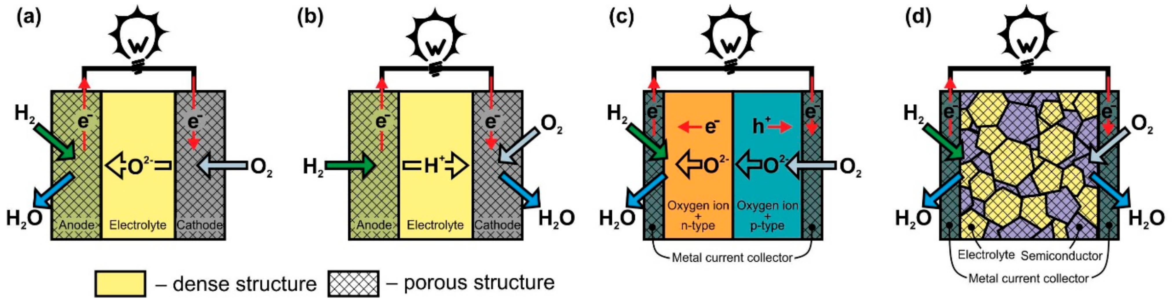
Figure 1. Scheme of operation of (a) oxygen-ion conducting electrolyte SOFC (O-SOFC), (b) proton-conducting electrolyte SOFC (H-SOFC), (c) double-layer fuel cells (DLFC), and (d) single-layer fuel cells (SLFC).
The open-circuit voltage (OCV) of the fuel cell (when there is no current through the external load) depends on the gradient of the oxygen chemical potential from the cathode and anode sides, and the temperature and pressure in the system [11]. Fuel cell OCV is around 1.1 V at 900 °C with air as oxidant and hydrogen as fuel. When a current is passed, the voltage at the terminals of the fuel cell drops due to its internal resistance, which is the sum of ohmic, polarization, and concentration losses. The voltage on a load can be expressed as:
(1)
where I is the current, Ri is the ohmic resistance of the SOFC components, η is the voltage associated with polarization losses (overpotential), and ηconc is the voltage due to concentration losses. The electrolyte layer makes the main contribution to ohmic losses, since its conductivity is 2–3 orders of magnitude lower than that of electrode materials [4]. Polarization losses (or polarization resistance) are determined by the processes of current formation at the three phase boundary (electrolyte–electrode–gas), which depend on many parameters, such as composition, structure, physicochemical properties of the electrolyte and electrode materials, temperature, and oxygen partial pressure; in addition, they are largely determined by the morphology of the three phase boundary, which, in turn, is set by the prehistory and methods of making electrodes [12]. Concentration losses arise as a result of a change in the reagent concentration in the reaction zone due to the difficulty in delivering reagents (O2 and fuel) to the reaction site and the removal of reaction products (H2O, CO2) through a porous electrode. Concentration losses are small when high porosity and small thickness of the electrodes. The internal resistance of the SOFC should be minimized as much as possible to achieve high specific power.
Most often, oxide materials with a fluorite structure such as Y2O3 or Sc2O3 stabilized ZrO2 (YSZ or ScSZ, respectively), and Gd2O3- or Sm2O3-doped CeO2 (GDC or SmDC, respectively) are used as electrolytes for O-SOFC [13,14,15][13][14][15]. In the overwhelming majority of cases, a composite based on Ni is used as an anode material [16[16][17][18],17,18], and the most commonly cathode materials of O-SOFC are La1-xSrxMnO3 (LSM) [19] and La1-xSrxCo1-yFeyO3 (LSCF) [20]. At the same time, extensive research isbeing conducted to find new electrode materials [6,21,22,23,24,25][6][21][22][23][24][25]. Another area of research that has the prospect of improving SOFC performances is the creation of nanostructures [26,27][26][27]. In particular, the introduction of nanosized dense layers with mixed ion-electron conductivity at the cathode–electrolyte interface can significantly reduce the polarization resistance [28,29][28][29]. Nanostructuring of electrodes also results in an increase in their catalytic activity and allows the direct use of hydrocarbon fuels [30,31,32,33][30][31][32][33].
A single SOFC is not suitable for practical use due to its low OCV; therefore, individual cells are connected in a stack to generate a sufficiently high voltage and power. The connection is made using a component called interconnect, which must possess purely electronic conductivity (without oxygen-ion conductivity). The interconnect makes contribution to the internal resistance of the SOFC stack and is an important component together with the anode, cathode, and electrolyte. Consequently, the development of interconnections is also given much attention [6,34,35][6][34][35].
The operation principle of proton-conducting electrolyte SOFC (Figure 1b) is similar to the one of O-SOFC. The difference is that when the fuel is oxidized at the anode, H+ enters the electrolyte lattice, and after transferring through the electrolyte, it takes part in the oxygen reduction reaction with the formation of water. It is believed that the formation of water on the cathode side is the advantage of H-SOFC, since, in this case, there is no fuel dilution at the anode. In addition, proton-conducting materials such as SrCeO3, BaZrO3, and BaCeO3 exhibit higher conductivity than that of YSZ or GDC at temperatures of 350–600 °C due to the relatively low activation energy of proton migration in solid oxides [36,37][36][37]. Thus, H-SOFC must have a higher power than O-SOFC at low temperatures. However, the properties of the electrolytes and electrodes still have to be improved to completely implement this concept. The main issues associated with the development of proton-conducting electrolytes are to increase chemical stability (prevent interaction with CO2 and H2O), improve sinterability, and suppress electronic conductivity [38,39][38][39]. The greatest hopes for a decrease in polarization losses in H-SOFC are pinned on the development of a cathode material with mixed oxygen-ion-proton-electron triple conductivity [40]. Presently, H-SOFC research is being conducted at the laboratory level with hydrogen as a fuel [38,39][38][39].
Electrolyte-free fuel cells can be divided into two classes according to the number of layers of dissimilar materials used to them fabrication: double-layer fuel cells (DLFC) and single-layer fuel cells (SLFC).
The DLFC concept (Figure 1c) was proposed by B. Zhu’s group in [41] and developed in [42]. These are the only publications that wresearchers were able to find on this construction. DLFCs are formed from two materials with mixed oxygen-ion and electronic conductivity of n- or p-type. In Ref. [41], the anode and cathode layers were formed from composites to achieve the desired properties of materials. The p-n junction formed at the interface between the two materials prevents the transfer of electrons through the structure of the fuel cell and, in fact, acts as an electrolyte layer with oxygen-ionic conduction in the TL-SOFC.
The SLFC idea was proposed in [43] in 2000. It was based on the assumption that one material can perform the functions of all SOFC components (anode, electrolyte, cathode) due to different types of conductivity at different oxygen partial pressures. The conception was tested on La0.9Sr0.1InO3-δ, which has oxygen ionic conductivity, but at the same time, has p-type conductivity in an oxidizing atmosphere and n-type in a reducing atmosphere. The specific power of Pt/La0.9Sr0.1InO3-δ/Pt cell at 800 °C was 3 mW∙cm−2. B. Zhu et al. changed the approach to the formation of SLFC functional layer by making it a porous nanocomposite from materials with oxygen-ionic and semiconducting conduction (Figure 1d) [41,44][41][44]. To date, various two- and more-phase composites from materials with different conductivity types have been used for SLFC fabrication. A review of the materials can be found in [8,45][8][45]. In particular, ceria–carbonate electrolytes possess H+ and O2− conduction [41,46][41][46]; therefore, in Figure 1d the formation of H2O on the cathode side is shown.
The development of SLFC has been going on for ten years, but the operation principle is still not entirely clear. Two main mechanisms have been proposed to explain the effect of blocking the electron flow through the SLFC functional layer [47,48,49][47][48][49]. The first mechanism consists of the formation of a p-n bulk heterojunction in the center of the composite layer due to the fact that, when exposed to hydrogen and air, electrons and holes concentration zones appear near the fuel and oxidizing current collectors, respectively [47]. The second mechanism is associated with the formation of a Schottky junction between the semiconductor component of the functional layer and the metal current collector on the SLFC anode side [48]. In addition, the role of metal current collectors, which are most often made of Ni and Ag, remains unclear. Do they only serve to transport electrons or also function as electrodes in the SLFC? Nevertheless, it should be recognized that the elimination of the electrolyte layer from the fuel cell design gives the EFFC the following advantages over the conventional three-layer SOFC: (1) ease of manufacture, since only one layer needs to be formed, and (2) the problems of thermomechanical matching of the components are excluded. The developers also declare that polarization losses are reduced because there is no fixed electrode–electrolyte interface. Comparison of the characteristics of SLFC and TL-SOFC made from the same materials indicates that a single-layer structure has similar or even little higher specific power values than a three-layer structure [41,46,48][41][46][48].
A comparison of features of SOFC designs with different electrolytes and without ones is presented in Table 1.
Table 1. Features of O-SOFC, H-SOFC, and FEFC.
| SOFC Type | Advantages | Disadvantages |
|---|---|---|
| O-SOFC | Well-studied There are industrial devices Potential for internal reforming |
Complexity of fabrication Limited selection of materials Low conductivity electrolyte High operating temperatures result in higher thermomechanical stresses and more significant degradation |
| O) | More research on electrolyte and electrode materials are required | Complexity of fabrication Internal reforming is questionable |
| DLFC | Simplicity of fabrication The problem of thermomechanical matching of cell materials is alleviated Wide selection of materials |
Poorly studied No internal reforming |
| SLFC | Simplicity of fabrication No problem with thermomechanical matching of cell materials Wide selection of materials |
Poorly studied Internal reforming is questionable |
2.2. Classification according to the Gas Spaces Separation
SOFC can be divided into three groups according to the criterion of supply of gas reagents: dual-chamber SOFC (DC-SOFC); single-chamber SOFC (SC-SOFC), which are also called “one-chamber”, “mixed-fuels”, or “mixed-reactant”; and no-chamber solid oxide fuel cells, which are most often called direct-flame SOFC (DF-SOFC) or flame fuel cells (FFC) (Figure 2).
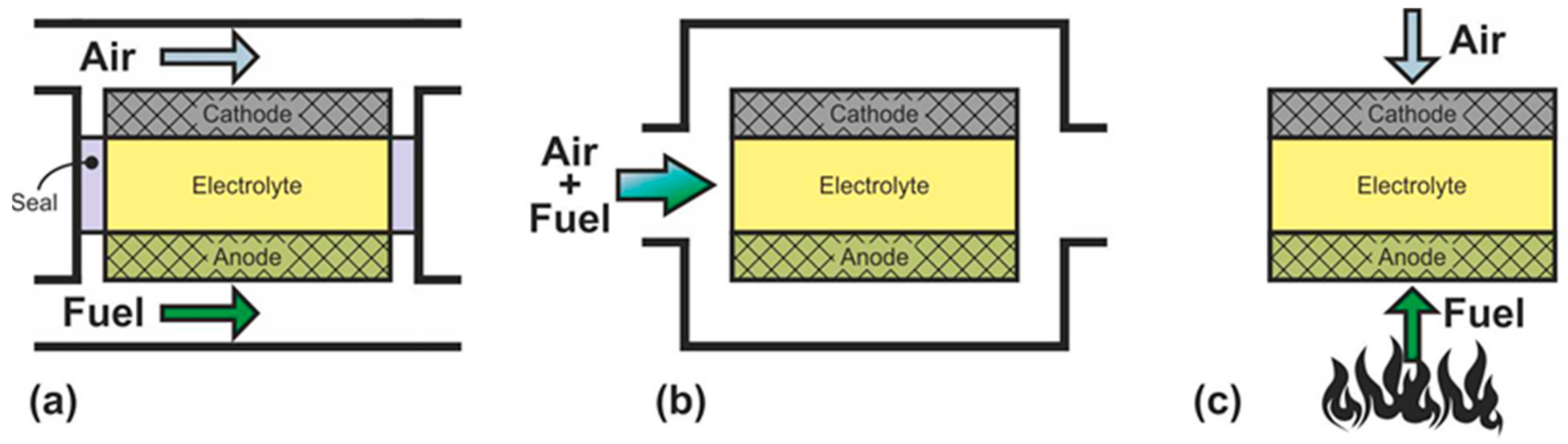
Figure 2. Schematics of (a) dual-chamber SOFC, (b) single-chamber SOFC, and (c) no-chamber SOFC.
In DC-SOFC, the reactants are separated: the oxidant is fed to the cathode, and the fuel is fed to the anode without any mixing (Figure 2a). The operation principle of this configuration was discussed in detail above. It is only recalled that the electromotive force arises by the gradient of the oxygen partial pressure between the separate electrode chambers. Dual-chamber SOFC are considered to the conventional design, and the abbreviation SOFC usually denotes separate-reactant solid oxide fuel cells.
In SC-SOFC, a mixture of fuel and oxidizer is fed into the working chamber (Figure 2b) [50]. In this case, the operation principle is based on the selectivity of the electrodes for the respective reactions. The anode must be electrochemically active for fuel oxidation and inert to oxidant reduction, and the cathode must exhibit selective oxygen reduction and inertness to fuel. The open circuit voltage in SC-SOFC depends on both the electrocatalytic activity and the selectivity of the electrodes. Specific designs of fuel cells can be implemented because there is no need to hermetically isolate the electrodes from each other: SC-SOFC with coplanar electrodes or single-face SC-SOFC and fully porous SOFC (FP-SOFC) or all porous SOFC (Figure 3). In the design with coplanar electrodes (Figure 3a), the electrodes are formed on the same side of the electrolyte, which simplifies the fabrication of SC-SOFC, increases its thermomechanical stability, and allows the formation of several elements at once [51]. In FP-SOFC (Figure 3b,c), the electrolyte layer between the electrodes is porous, which makes the construction cheaper due to low electrolyte sintering temperatures [7]. However, a significant drawback of the specific SC-SOFC designs is the low specific power amounting to 1–40 mW·cm−2 at 750 °C [7,52,53][7][52][53]. Only in [54] was a specific power higher than 200 mW·cm−2 at 750 °C obtained for FP-SOFC. Moreover, in SOFC with coplanar electrodes, a strong degradation of characteristics is observed [7].
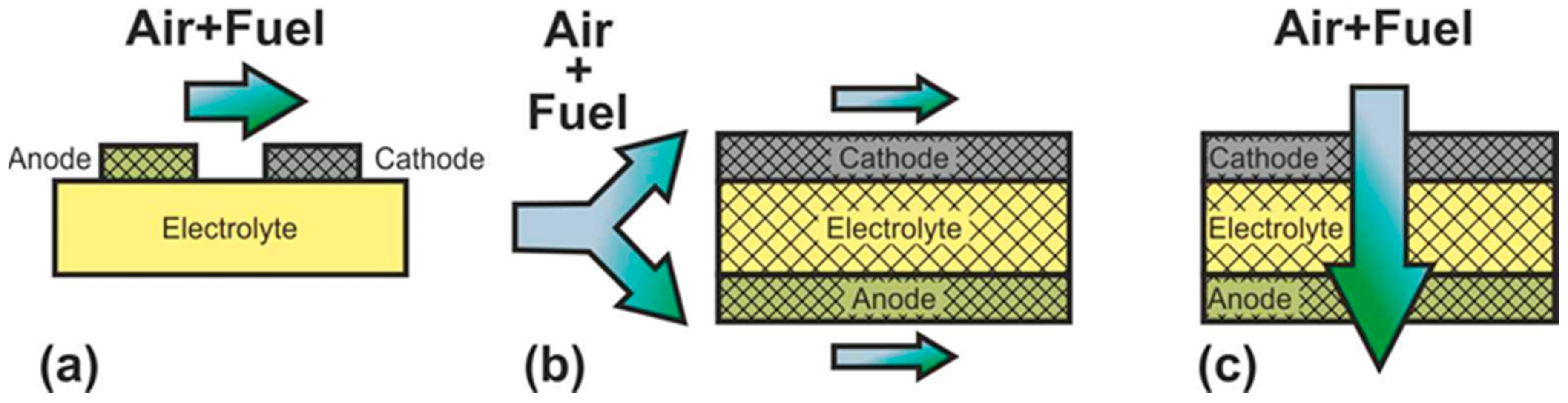
Figure 3.
Schematics of (
a
) SC-SOFC with coplanar electrodes and fully porous SOFC in (
b
) flow-by and (
c
) flow-through configuration.
In a mixed-reactant design proposed by M. Horiuchi et al. [55], the fuel cell is placed directly above the burning flame (Figure 2c). The anode is close to the fuel-rich flame, and the cathode has access to ambient air. In this case, the flame provides the fuel cell with heat, carries out the reforming of carbon-hydrogen fuel, and sets the difference in the oxygen partial pressure between the two electrodes by consuming oxygen at the anode. The operation principle of the DF-SOFC is close to the operation principle of the SC-SOFC since gas separation is not required. However, requirements for the selectivity of the catalysts are reduced because the DF-SOFC electrodes are placed in different atmospheres.
The mixed-reactant fuel cells (SC-SOFC and DF-SOFC) have several advantages over DC-SOFC [7[7][56],56], especially for small devices. The absence of the need to separate gas spaces results in increased thermomechanical stability and a simpler and compact design both of the fuel cell and the gas manifold. This, in turn, makes the fabrication of a single cell, and its collection in the stack is easier, whereas the formation of necessary effective sealing at high temperatures for separate-reactant SOFC is a challenge [57,58][57][58]. Moreover, the rigid connection of the cell to other stack components can result in mechanical stress and even breakage. Another advantage of mixed-reactant SOFC over DC-SOFC is the ability to maintain the operating temperature without the need to supply additional heat from outside. Herewith, DF-SOFC have a number of other advantages: the ability to use almost any hydrocarbon fuel, including gases, liquids, and solids, quick start-up, and the problem of the porous electrodes coking is less serious than that in SC-SOFC.
On the other hand, mixed-reactant SOFC have serious drawbacks that impede their practical use [7,56][7][56]. Electrode selectivity plays a key role in the functioning of SC-SOFC. However, fully selective materials have not been found yet. In particular, all SOFC cathode materials catalyze methane oxidation [59]. Due to parasitic reactions occurring at the electrodes, SC-SOFCs have a low electrical efficiency (~1%), as well as a low level of fuel utilization (about 10%) [7]. However, it has recently been shown that the use of a nanocomposite consisting of materials with different functions as a cathode can significantly increase its selectivity and thereby increase the efficiency of the entire SC-SOFC [60]. The electrical efficiency of DF-SOFC is even lower (0.45% [61]), which is associated not so much with the electrode selectivity but with the fact that the fuel is consumed in the combustion reaction. In addition, the significant material stresses arising from thermal load associated with placing the cell near an open flame are a particular problem for DF-SOFC. The use of an air/fuel mixture in SC-SOFC is a risk of ignition and/or explosion. Therefore, in SC-SOFC, hydrogen is not used, and most often, methane is used as a fuel. The separate-reactant SOFC are much safer and have significantly higher electrical efficiency (up to 60% [62]) and a level of fuel utilization (about 80% [62]). Apparently, precisely this huge difference in the efficiency, as well as the immaturity of the technology, are the reason why the mixed-reactant SOFC are not even mentioned in the classifications proposed in [3,4,5,6][3][4][5][6].
Table 2 summarizes the advantages and disadvantages of DC-SOFC, SC-SOFC, and DF-SOFC.
Table 2. Features of DC-SOFC, SC-SOFC, and DF-SOFC.
| SOFC Type | Advantages | Disadvantages | |
|---|---|---|---|
| DC-SOFC | Well-studied There are industrial devices High efficiency High level of fuel utilization Fire and explosion safety |
Complexity of fabrication Matching of thermal expansion of cell materials are required Slow start up |
|
| H-SOFC | Higher conductive electrolyte Low operating temperatures suggest less thermomechanical stress and less degradation No fuel dilution with reaction products (H | ||
| SC-SOFC | 2 | Simplicity of fabrication Simplified use of hydrocarbons as fuel High resistance to thermomechanical stress |
More selective electrodes are required Low efficiency Low level of fuel utilization Flammable and explosive Coking of electrodes |
| DF-SOFC | Simplicity of fabrication Simplified use of hydrocarbons as fuel Potential for quick start up |
More selective electrodes are required Low efficiency Low level of fuel utilization High thermomechanical stress Coking of electrodes |
Currently, DF-SOFC are fabricated based on oxygen-ion-conducting electrolytes [56]. To make SC-SOFC, oxygen-ion conducting electrolytes are also used in most cases [7], but there are single works on the use of proton conducting electrolytes (for example, [63,64][63][64]). It is obvious that EFFC operation in the condition of mixed reactants is impossible unless the current collectors possess selectivity to various reactions.
At the end of this section, it is worth mentioning the so-called flame-assisted fuel cells or flame fuel cells (FFC) [65,66,67][65][66][67]. This concept implies two devices integrated with each other: the combustion system and the SOFC itself. The premixed combustion system avoids complete oxidation of the fuel with excess air, which is present in conventional DF-SOFC. As a result, more fuel enters the SOFC anode for electrochemical power generation. Herewith, the air is separately supplied to the fuel cell cathode. Thus, from the point of view of classification, the SOFC operates in a dual-chamber mode. The FFC concept allows the use of a hydrocarbon fuel without any catalysts. However, the efficiency and level of fuel utilization of the FFC are low, although higher than those of the DF-SOFC. The highest electrical efficiency of 6% and fuel utilization coefficient of 23% of FFC have been achieved in [68].
2.3. Classification according to Operating Temperature
The first SOFC operated at temperatures of 900–1000 °C [3]. High operating temperatures ensured a low internal resistance of the fuel cell due to the high conductivity of the electrolyte and a high rate of electrode reactions and, accordingly, high specific power as well as the possibility of internal reforming of hydrocarbon fuel. However, high operating temperatures also cause a number of problems related to sealing, the morphological stability of electrodes, the chemical stability of cell components, and the heat resistance of accessories. These problems result in a high cost of cells and a reduction in their lifetime. Therefore, a strategy to reduce the operating temperatures of SOFC was adopted. Lower operating temperatures allow the use of new materials (in particular, steel interconnects [34]), reduce the SOFC cost, reduce degradation, and implement faster start-up.
At the present time, SOFC are usually divided into high-, medium-, and low-temperature categories. However, there is still no consensus on temperature ranges. In works [69,70,71][69][70][71] SOFC are divided only by medium temperature (500–750 °C) and high temperature (above 750 °C). The authors of [72] consider that the definitions of “low-temperature” and “medium-temperature” are a synonyms, and 800 °C is the upper limit of this temperature range. The majority of researchers dividing SOFCs into three temperature classes also define 800 °C as the boundary of medium–high temperatures [6,73,74,75][6][73][74][75]. Herewith, the boundary between low and medium temperatures varies: in [6,74][6][74] and [73[73][75],75], 650 and 600 °C are marked, respectively. It should be noted that, usually, the physical reasons for choosing a particular temperature as the range boundary are not explicitly indicated, which, most likely, is the reason for the differences.
The temperature of 800 °C between high- and medium-temperature ranges, accepted by most authors, implies the upper limit of the expediency of using steel interconnects for the stack manufacture [34]. In Ref. [70], it was proposed to make the possibility of implementing internal reforming of methane as a criterion for determining the lower operating temperature of SOFC. The authors of [70] decided that 500 °C is the lowest temperature at which methane internal reforming can occur on a suitable catalyst (catalyst was not specified), although it was recognized that this temperature is controversial. In a recent review [76], it was shown that methane internal reforming at the most common Ni-based anode can occur only at temperatures above 600 °C. Therefore, wresearchers propose to set the temperature of 600 °C as the boundary of the medium- and low-temperature region, thereby dividing SOFC into cells that can directly use methane as fuel and cells that require external reforming. Thus, in this work, SOFC operating in temperature ranges above 800 °C, from 600 to 800 °C, and below 600 °C are considered high-, medium-, and low-temperature SOFC, respectively.
The above arguments for lowering the operating temperature generally refer to well-studied separate-reactant O-SOFC. Alternative designs of SLFC, DLFC and H-SOFC have also been developed to reduce operating temperatures. H-SOFC have higher specific powers in the low-temperature region than those of O-SOFC due to more conductive electrolytes. The temperature range of H-SOFC research is 450–750 °C, and the maximum specific power of H-SOFC at 700 °C reaches ~1000 mW∙cm−2 [77,78][77][78]. The maximum temperature of SLFC testing also did not exceed 750 °C, and the obtained maximum specific powers at 550 °C varied in a wide range, from 200 to 1000 mW∙cm−2 [45]. DLFC studies were carried out at temperatures of about 550 °C, and the maximum specific powers were 560 and 280 mW∙cm−2 [41,42][41][42].
The development of mixed-reactant SOFC was aimed at simplifying the design and did not imply a decrease in operating temperature. The operating temperatures of SC-SOFC vary from 300 to 950 °C [7], and ones of DF-SOFC vary from 400 to 850 °C [79,80,81][79][80][81]. The data on the maximum specific power of SC-SOFC and DF-SOFC presented in the literature have a significant scatter from tens to several hundred mW∙cm−2. Their comparison is difficult since the power of mixed-reactant SOFC depends on not only the operating temperature, structure, and materials of the fuel cell, but also on the type of hydrocarbon fuel and the fuel–oxidizer ratio.