 +1 credit
| Version | Summary | Created by | Modification | Content Size | Created at | Operation |
|---|---|---|---|---|---|---|
| 1 | Azmi Mohd Shariff | + 4376 word(s) | 4376 | 2022-02-21 08:42:05 | | | |
| 2 | Catherine Yang | Meta information modification | 4376 | 2022-03-01 02:52:04 | | |
Video Upload Options
The emerging economic activities, modernization of technology and progressive transition from coal utilization to low-carbon fuel drive the rising energy demand. Natural gas is well-known as clean energy resources for electricity generation and fuel for transportation. Currently, CO2 and H2S content in gas fields accounts for up to 90% and 15%, respectively. Apart from fulfilling the market demand, the removal of these contaminants from natural gas is critical due to their corrosive natures, low heating value of natural gas and greenhouse gas effect. To date, numerous gas fields remain unexplored due to high presence of contaminants. Several technologies such as absorption, adsorption, membrane separation and cryogenic distillation have been developed for natural gas sweetening. This entry comprehensively discussed the mechanisms and state-of-the-art of these conventional technologies.
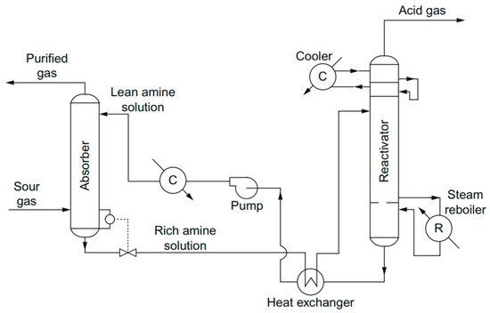
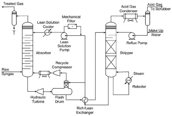
1. Absorption
At the beginning of the 21st century, the first solvent that was used for the absorption process was a carbonate solution that was applied in dry ice plants to separate CO2 from flue gas [1]. Sodium carbonate solutions were rapidly phased out after the introduction of alkanolamine, as this solvent absorbs CO2 faster and can attain extremely high CO2 removal efficiency [1]. Starting in 1930, primary generation alkanolamine solvents such as diethanolamine (DEA), (MEA) and diglycolamine (DGA) were developed for the CO2 removal process [1][2][3]. Then, secondary alkanolamine solvents such as diethanolamine (DEA) and diisopropanolamine (DIPA) were invented as alternatives to MEA [4]. The difference between primary and secondary is that the primary alkanolamines contain hydrogen atoms directly bonded to nitrogen [4]. A tertiary alkanoamine solvent, which is methyldiethanolamine (MDEA), was proposed by Frazier and Kohl to promote the selectivity of H2S [4]. In 1983, 2-amino-2-methyl-1-propanol (AMP), which hindered amines, was developed at Exxon Research and Engineering Company [5]. From 1995 to now, there has been a lot of research into sterically hindered amines as potential alkanol amine absorbents. There are also lots of studies that report the promoters, such as piperazine, potassium carbonate, mono ethanol amine (MEA) and diethanolamine (DEA), that can be blended with amine solvent, such as MDEA, to enhance the reaction rates of the absorption process [4]. Starting in 2005, the interest in the usage of amino acid for acid gas removal started to develop in using the sodium or potassium salt glycine (NaGly), which is the simplest primary amino acid, for CO2 capture [6]. Recently, in 2003, ionic liquids, ILs, were branded as “solvents of the future”, as they have the potential as alternative solvents for acid gas removal [7][8].
2. Adsorption
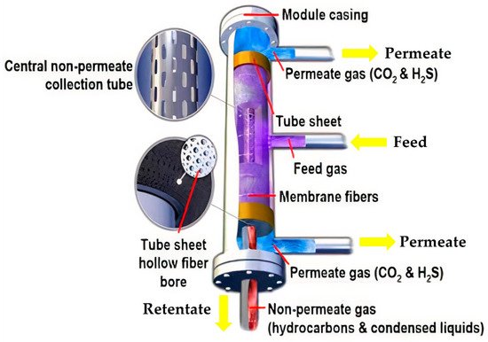
3. Membrane
4. Cryogenic Distillation
References
- Knuutila, H.; Svendsen, H.F.; Juliussen, O. Kinetics of carbonate based CO2 capture systems. Energy Procedia 2009, 1, 1011–1018.
- Bottoms, R.R. Process for Separating Acidic Gases. U.S. Patent 1783901A, 7 October 1930. Available online: https://patents.google.com/patent/US1783901A/en (accessed on 29 October 2021).
- Vega, F.; Sanna, A.; Navarrete, B.; Maroto-Valer, M.; Cortés, V. Degradation of amine-based solvents in CO2 capture process by chemical absorption. Greenh. Gases Sci. Technol. 2014, 4, 707–733.
- Vega, F.; Cano, M.; Camino, S.; Fernández, L.M.G.; Portillo, E.; Navarrete, B. Solvents for Carbon Dioxide Capture. In Capture and Oil Recovery, Karamé, I., Shaya, J., Srou, H., Eds.; IntechOpen: Rijeka, Croatia, 2018; p. 8.
- Shah, M.S.; Tsapatsis, M.; Siepmann, J.I. Hydrogen Sulfide Capture: From Absorption in Polar Liquids to Oxide, Zeolite, and Metal-Organic Framework Adsorbents and Membranes. Chem. Rev. 2017, 117, 9755–9803.
- Weiland, R.H.; Hatcher, N.A.; Nava, J.L. Post-combustion CO2 Capture with Amino-Acid Salts. GPA Eur. 2010, 22, 24.
- Rogers, R.D.; Seddon, K.R. Ionic Liquids-Solvents of the Future? Science 2003, 302, 792–793.
- Greer, A.J.; Jacquemin, J.; Hardacre, C. Industrial Applications of Ionic Liquids. Molecules 2020, 25, 5207.
- Speight, J.G. Fouling During Gas Cleaning. In Fouling in Refineries; Gulf Professional Publishing: Boston, MA, USA, 2015; pp. 351–374.
- Ban, Z.H.; Keong, L.K.; Shariff, A.M. Physical absorption of CO2 capture: A review. Adv. Mater. Res. 2014, 917, 134–143.
- Miller, B.G. 7-Clean Coal Technologies for Advanced Power Generation. In Clean Coal Engineering Technology; B Butterworth-Heinemann: Boston, MA, USA, 2011; pp. 251–300.
- Ghasem, N. Chapter 21—CO2 removal from natural gas. In Advances in Carbon Capture; Rahimpour, M.R., Farsi, M., Makarem, M.A., Eds.; Woodhead Publishing: Sawston, UK, 2020; pp. 479–501.
- Hu, G.; Smith, K.H.; Wu, Y.; Mumford, K.A.; Kentish, S.E.; Stevens, G.W. Carbon dioxide capture by solvent absorption using amino acids: A review. Chin. J. Chem. Eng. 2018, 26, 2229–2237.
- Masoumi, S.; Rahimpour, M.R.; Mehdipour, M. Removal of carbon dioxide by aqueous amino acid salts using hollow fiber membrane contactors. J. CO2 Util. 2016, 16, 42–49.
- Ciftja, A.F.; Hartono, A.; Svendsen, H.F. Selection of amine amino acids salt systems for CO2 capture. Energy Procedia 2013, 37, 1597–1604.
- Erga, O.; Juliussen, O.; Lidal, H. Carbon dioxide recovery by means of aqueous amines. Energy Convers. Manag. 1995, 36, 387–392.
- Wang, B.; Zhang, K.; Ren, S.; Hou, Y.; Wu, W. Efficient capture of low partial pressure H2S by tetraethyl ammonium amino acid ionic liquids with absorption-promoted solvents. RSC Adv. 2016, 6, 101462–101469.
- Rouquerol, J.; Avnir, D.; Everett, D.H.; Fairbridge, C.; Haynes, M.; Pernicone, N.; Ramsay, J.D.F.; Sing, K.S.W.; Unger, K.K. Guidelines for the Characterization of Porous Solids. Stud. Surf. Sci. Catal. 1994, 87, 1–9.
- Kyzas, G.Z.; Fu, J.; Matis, K.A. The Change from Past to Future for Adsorbent Materials in Treatment of Dyeing Wastewaters. Materials 2013, 6, 5131–5158.
- Robens, E. Some intriguing items in the history of adsorption. Stud. Surf. Sci. Catal. 1994, 87, 109–118.
- Gregg, S.J.; Sing, K.S.W.; Salzberg, H.W. Adsorption Surface Area and Porosity. J. Electrochem. Soc. 1967, 114, 279C.
- Adam, N.K. The Adsorption of Gases and Vapours. Nature 1945, 155, 154–155.
- Chappuis, P. Ueber die Wärmeerzeugung bei der Absorption der Gase durch feste Körper und Flüssigkeiten. Ann. Phys. 1883, 255, 21–38.
- Sircar, S. Publications on Adsorption Science and Technology. Adsorption 2000, 6, 359–365.
- Sircar, S. Applications of Gas Separation by Adsorption for the Future. Adsorpt. Sci. Technol. 2001, 19, 347–366.
- Ling, J.; Ntiamoah, A.; Xiao, P.; Webley, P.A.; Zhai, Y. Effects of feed gas concentration, temperature and process parameters on vacuum swing adsorption performance for CO2 capture. Chem. Eng. J. 2015, 265, 47–57.
- Tao, L.; Xiao, P.; Qader, A.; Webley, P.A. CO2 capture from high concentration CO2 natural gas by pressure swing adsorption at the CO2CRC Otway site, Australia. Int. J. Greenh. Gas Control 2019, 83, 1–10.
- Grande, C.A. Advances in Pressure Swing Adsorption for Gas Separation. ISRN Chem. Eng. 2012, 2012, 982934.
- Ho, M.T.; Allinson, G.W.; Wiley, D.E. Reducing the Cost of CO2 Capture from Flue Gases Using Pressure Swing Adsorption. Ind. Eng. Chem. Res. 2008, 47, 4883–4890.
- Fouladi, N.; Makarem, M.A.; Sedghamiz, M.A.; Rahimpour, H.R. Chapter 11—CO2 adsorption by swing technologies and challenges on industrialization. In Advances in Carbon Capture; Rahimpour, M.R., Farsi, M., Makarem, M.A., Eds.; Woodhead Publishing: Sawston, UK, 2020; pp. 241–267.
- Bonnissel, M.P.; Luo, L.; Tondeur, D. Rapid Thermal Swing Adsorption. Ind. Eng. Chem. Res. 2001, 40, 2322–2334.
- Mérel, J.; Clausse, M.; Meunier, F. Carbon dioxide capture by indirect thermal swing adsorption using 13X zeolite. Environ. Prog. 2006, 25, 327–333.
- Chaffee, A.L.; Knowles, G.; Liang, Z.; Zhang, J.; Xiao, P.; Webley, P. CO2 capture by adsorption: Materials and process development. Int. J. Greenh. Gas Control 2007, 1, 11–18.
- Grande, C.A.; Rodrigues, A.E. Electric Swing Adsorption for CO2 removal from flue gases. Int. J. Greenh. Gas Control 2008, 2, 194–202.
- Le Cloirec, P. Adsorption onto Activated Carbon Fiber Cloth and Electrothermal Desorption of Volatile Organic Compound (VOCs): A Specific Review. Chin. J. Chem. Eng. 2012, 20, 461–468.
- Berger, A.H.; Bhown, A.S. Comparing physisorption and chemisorption solid sorbents for use separating CO2 from flue gas using temperature swing adsorption. Energy Procedia 2011, 4, 562–567.
- Xing, W.; Liu, C.; Zhou, Z.; Zhou, J.; Wang, G.; Zhuo, S.; Xue, Q.; Song, L.; Yan, Z. Oxygen-containing functional group-facilitated CO2 capture by carbide-derived carbons. Nanoscale Res. Lett. 2014, 9, 189.
- Kulkarni, S.; Kaware, J. Regeneration and recovery in adsorption-a review. Int. J. Innov. Sci. Eng. Technol. 2014, 1, 61–64.
- Costa, C.; Cornacchia, M.; Pagliero, M.; Fabiano, B.; Vocciante, M.; Reverberi, A. Hydrogen Sulfide Adsorption by Iron Oxides and Their Polymer Composites: A Case-Study Application to Biogas Purification. Materials 2020, 13, 4725.
- Hussain, M.; Abbas, N.; Fino, D.; Russo, N. Novel mesoporous silica supported ZnO adsorbents for the desulphurization of biogas at low temperatures. Chem. Eng. J. 2012, 188, 222–232.
- Montes, D.; Tocuyo, E.; Gonzalez, E.; Rodríguez, D.; Solano, R.; Atencio, R.; Ramos, M.A.; Moronta, A. Reactive H2S chemisorption on mesoporous silica molecular sieve-supported CuO or ZnO. Microporous Mesoporous Mater. 2013, 168, 111–120.
- Lincke, M.; Petasch, U.; Gaitzsch, U.; Tillmann, A.; Tietze, M.; Niebling, F. Chemoadsorption for separation of hydrogen sulfide from biogas with iron hydroxide and sulfur recovery. Chem. Eng. Technol. 2020, 43, 1564–1570.
- De Oliveira, L.H.; Meneguin, J.G.; Pereira, M.V.; da Silva, E.A.; Grava, W.M.; do Nascimento, J.F.; Arroyo, P.A. H2S adsorption on NaY zeolite. Microporous Mesoporous Mater. 2019, 284, 247–257.
- Thanakunpaisit, N.; Jantarachat, N.; Onthong, U. Removal of Hydrogen Sulfide from Biogas using Laterite Materials as an Adsorbent. Energy Procedia 2017, 138, 1134–1139.
- Abdullah, A.H.; Mat, R.; Aziz, A.S.A.; Roslan, F. Use of kaolin as adsorbent for removal of hydrogen sulphide from biogas. Chem. Eng. Trans. 2017, 56, 763–768.
- Lin, Y.-H.; Chen, Y.-C.; Chu, H. The mechanism of coal gas desulfurization by iron oxide sorbents. Chemosphere 2015, 121, 62–67.
- Chiarioni, A.; Reverberi, A.; Fabiano, B.; Dovi’, V. An improved model of an ASR pyrolysis reactor for energy recovery. Energy 2006, 31, 2460–2468.
- Elyassi, B.; Al Wahedi, Y.; Rajabbeigi, N.; Kumar, P.; Jeong, J.S.; Zhang, X.; Kumar, P.; Balasubramanian, V.V.; Katsiotis, M.S.; Mkhoyan, K.A.; et al. A high-performance adsorbent for hydrogen sulfide removal. Microporous Mesoporous Mater. 2014, 190, 152–155.
- Belmabkhout, Y.; Heymans, N.; De Weireld, G.; Sayari, A. Simultaneous Adsorption of H2S and CO2 on Triamine-Grafted Pore-Expanded Mesoporous MCM-41 Silica. Energy Fuels 2011, 25, 1310–1315.
- Huang, H.Y.; Yang, R.T.; Chinn, D.; Munson, C.L. Amine-Grafted MCM-48 and Silica Xerogel as Superior Sorbents for Acidic Gas Removal from Natural Gas. Ind. Eng. Chem. Res. 2003, 42, 2427–2433.
- Ma, X.; Wang, X.; Song, C. “Molecular Basket” Sorbents for Separation of CO2 and H2S from Various Gas Streams. J. Am. Chem. Soc. 2009, 131, 5777–5783.
- Georgiadis, A.; Charisiou, N.; Goula, M. Removal of Hydrogen Sulfide From Various Industrial Gases: A Review of The Most Promising Adsorbing Materials. Catalysts 2020, 10, 521.
- Bülow, M.; Lutz, W.; Suckow, M. The mutual transformation of hydrogen sulphide and carbonyl sulphide and its role for gas desulphurization processes with zeolitic molecular sieve sorbents. Stud. Surf. Sci. Catal. 1999, 120, 301–345.
- Gordano, A.; Buonomenna, M.G.; Idris, A.; Ahmed, I.; Noor, N.M.; Liu, J.; Xu, T.; Shao, G.; Jana, S.; Purkait, M.K.; et al. Membrane Technologies and Applications; Purkait, M.K., Mohanty, K., Eds.; CRC Press: Boca Raton, FL, USA, 2012.
- Liu, C.; Greer, D.W.; O’Leary, B.W. Advanced Materials and Membranes for Gas Separations: The UOP Approach. ACS Symp. Ser. 2016, 1224, 119–135.
- Bernardo, P.; Drioli, E.; Golemme, G. Membrane Gas Separation: A Review/State of the Art. Ind. Eng. Chem. Res. 2009, 48, 4638–4663.
- Mordor Intelligence. Gas Separation Membrane Market-Growth, Trends, COVID-19 Impact, and Forecasts (2021–2026). 2020. Available online: https://www.mordorintelligence.com/industry-reports/gas-separation-membrane-market (accessed on 25 October 2021).
- Pabby, A.K.; Rizvi, S.S.H.; Requena, A.M.S. Handbook of Membrane Separations-Chemical, Pharmaceutical, Food, and Biotechnological Applications, 2nd ed.; CRC Press: Boca Raton, FL, USA, 2015.
- He, X.; Hägg, M.-B. Membranes for Environmentally Friendly Energy Processes. Membranes 2012, 2, 706–726.
- Jariwala, A. High H2S Gas Field Monetization: A Novel Approach. In Proceedings of the Offshore Technology Conference, Houston, TX, USA, 6–9 May 2019.
- Lin, H.; White, L.S.; Lokhandwala, K.; Baker, R.W. Natural Gas Purification. In Encyclopedia of Membrane Science and Technology; John Wiley & Sons, Inc.: Hoboken, NJ, USA, 2013; pp. 1–25.
- Sanghani, P.; Kumar, H.; Ghorbani, N.; Morisato, A.; Mahley, G. Sour Gas Has A Sweeter Future-Bulk H2S Removal Using Polymeric Cellulose Triacetate Based Membranes. In Proceedings of the Abu Dhabi International Petroleum Exhibition & Conference 2020, Abu Dhabi, United Arab Emirates, 11 November 2020.
- Callison, A.; Davidson, G. Offshore processing plant uses membranes for CO2 removal. Oil Gas J. 2007, 105, 56–65.
- Jusoh, N.; Lau, K.K.; Shariff, A.M.; Yeong, Y.F. Capture of bulk CO2 from methane with the presence of heavy hydrocarbon using membrane process. Int. J. Greenh. Gas Control 2014, 22, 213–222.
- Jusoh, N.; Lau, K.K.; Shariff, A.M. Removal of Bulk CO2 from Methane with the Presenceof Heavy Hydrocarbon using Polyimide Membrane. J. Teknol. 2014, 69, 41–46.
- Nafisi, V.; Hägg, M.B. Gas separation properties of ZIF-8/6FDA-durene diamine mixed matrix membrane. Sep. Purif. Technol. 2014, 128, 31–38.
- Zhu, W.; Hrabanek, P.; Gora, L.; Kapteijn, F.; Moulijn, J.A. Role of Adsorption in the Permeation of CH4 and CO2 through a Silicalite-1 Membrane. Ind. Eng. Chem. Res. 2006, 45, 767–776.
- Li, S.; Martinek, J.G.; Falconer, J.L.; Noble, R.D.; Gardner, T.Q. High-Pressure CO2/CH4 Separation Using SAPO-34 Membranes. Ind. Eng. Chem. Res. 2005, 44, 3220–3228.
- Li, S.; Falconer, J.L.; Noble, R.D. Improved SAPO-34 membranes for CO2/CH4 separations. Adv. Mater. 2006, 18, 2601–2603.
- Himeno, S.; Tomita, T.; Suzuki, K.; Nakayama, K.; Yajima, K.; Yoshida, S. Synthesis and permeation properties of a DDR-type zeolite membrane for separation of CO2/CH4 gaseous mixtures. Ind. Eng. Chem. Res. 2007, 46, 6989–6997.
- Mubashir, M.; Fong, Y.Y.; Keong, L.K.; Sharrif, M.A.B. Synthesis and performance of deca-dodecasil 3 rhombohedral (ddr)-type zeolite membrane in CO2 separation—A review. ASEAN J. Chem. Eng. 2015, 14, 48–57.
- Poshusta, J.C.; Tuan, V.A.; Pape, E.A.; Noble, R.D.; Falconer, J.L. Separation of light gas mixtures using SAPO-34 membranes. AIChE J. 2000, 46, 779–789.
- Cui, Y.; Kita, H.; Okamoto, K.-I. Preparation and gas separation performance of zeolite T membrane. J. Mater. Chem. 2004, 14, 924–932.
- Lu, H.T. The Impact of Impurities on the Performance of Cellulose Triacetate Membranes for CO2 Separation. Ph.D. Thesis, Chemical Engineering Department, School of Chemical and Biomedical Engineering, The University of Melbourne, Melbourne, Australia, 2018.
- Chatterjee, G.; Houde, A.; Stern, S. Poly(ether urethane) and poly(ether urethane urea) membranes with high H2S/CH4 selectivity. J. Membr. Sci. 1997, 135, 99–106.
- Sadeghi, M.; Talakesh, M.M.; Shamsabadi, A.A.; Soroush, M. Novel Application of a Polyurethane Membrane for Efficient Separation of Hydrogen Sulfide from Binary and Ternary Gas Mixtures. ChemistrySelect 2018, 3, 3302–3308.
- Harrigan, D.J.; Yang, J.; Sundell, B.J.; Lawrence III, J.A.; O’Brien, J.T.; Ostraat, M.L. Sour gas transport in poly (ether-b-amide) membranes for natural gas separations. J. Membr. Sci. 2020, 595, 117497.
- Achoundong, C.S.K.; Bhuwania, N.; Burgess, S.K.; Karvan, O.; Johnson, J.R.; Koros, W.J. Silane Modification of Cellulose Acetate Dense Films as Materials for Acid Gas Removal. Macromolecules 2013, 46, 5584–5594.
- Schlumberger. Petronas Gas Plant Reduces Costs with Dual-Core Acid Gas Removal Membranes. 2018. Available online: https://www.slb.com/resource-library/case-study/osf/cynara-pn-1-petronas-malaysia-cs (accessed on 25 October 2021).
- Schlumberger. CYNARA-Acid Gas Removal Membrane Systems. 2016. Available online: https://www.slb.com/well-production/processing-and-separation/gas-treatment/cynara-acid-gas-removal-membrane-systems (accessed on 25 October 2021).
- Bhide, B.; Voskericyan, A.; Stern, S. Hybrid processes for the removal of acid gases from natural gas. J. Membr. Sci. 1998, 140, 27–49.
- Rezakazemi, M.; Heydari, I.; Zhang, Z. Hybrid systems: Combining membrane and absorption technologies leads to more efficient acid gases (CO2 and H2S) removal from natural gas. J. CO2 Util. 2017, 18, 362–369.
- Liebmann, A.J. History of distillation. J. Chem. Educ. 1956, 33, 166.
- Taylor, F.S. The evolution of the still. Ann. Sci. 1945, 5, 185–202.
- Chambers, J.M. Alcohol Distillation Process. U.S. Patent 2647078, 17 December 1949. Available online: https://patents.google.com/patent/US2647078A/en (accessed on 27 October 2021).
- Kaymak, D.B.; Luyben, W.L.; Smith IV, O.J. Effect of relative volatility on the quantitative comparison of reactive distillation and conventional multi-unit systems. Ind. Eng. Chem. Res. 2004, 43, 3151–3162.
- Department of Chemical and Environmental Process Engineering. Packed Distillation Columns; Budapest University of Technology and Economics: Budapest, Hungary, 2016; pp. 1–7.
- Blahušiak, M.; Kiss, A.; Kersten, S.; Schuur, B. Quick assessment of binary distillation efficiency using a heat engine perspective. Energy 2016, 116, 20–31.
- Pilling, M.; Holden, B.S. Choosing trays and packings for distillation. Am. Inst. Chem. Eng. CEP 2009, 105, 44–50.
- Spiegel, L.; Duss, M. Structured Packings; Elsevier Inc.: Amsterdam, The Netherlands, 2014.
- Patil, K.; Choudhary, P.; Bhatia, T. Distillation Operations: Methods, Operational and Design Issues. In Proceedings of the National Conference on Advances in Heat & Mass Transfer, FAMT, Ratnagiri, India, 30–31 October 2009; pp. 1–9.
- Agarwal, S.; Taylor, R. Distillation Column Design Calculations Using a Nonequilibrium Model. Ind. Eng. Chem. Res. 1994, 33, 2631–2636.
- Kolmetz, K.; Ng, W.K.; Lee, S.H.; Lim, T.Y.; Summers, D.R.; Soyza, C.A. Optimize distillation column design for improved reliability in operation and maintenance. Asia-Pac. J. Chem. Eng. 2007, 2, 294–307.
- Kolmetz, K.; Jaya, A. Distillation Column Reboiler Selection, Sizing, and Troubleshooting. In Kolmetz Handbook of Process Equipment Design; KLM Technology Group: Johor Bahru, Malaysia, 2013; Available online: https://www.klmtechgroup.com/PDF/EDG-SYS/ENGINEERING-DESIGN-GUIDELINES-reboiler-Rev1.3web.pdf (accessed on 27 October 2021).
- Taqvi, S.A.; Tufa, L.D.; Muhadizir, S. Optimization and Dynamics of Distillation Column Using Aspen Plus®. Procedia Eng. 2016, 148, 978–984.
- Font-Palma, C.; Cann, D.; Udemu, C. Review of Cryogenic Carbon Capture Innovations and Their Potential Applications. J. Carbon Res. 2021, 7, 58.
- Fitzmorris, R.E.; Mah, R.S.H. Improving distillation column design using thermodynamic availability analysis. AIChE J. 1980, 26, 265–273.

