 +1 credit
| Version | Summary | Created by | Modification | Content Size | Created at | Operation |
|---|---|---|---|---|---|---|
| 1 | Khairy Fathy Abdelsayed Sayed | + 1215 word(s) | 1215 | 2022-02-18 07:18:55 | | | |
| 2 | Nora Tang | + 9 word(s) | 1224 | 2022-02-28 03:33:14 | | | | |
| 3 | Nora Tang | -6 word(s) | 1218 | 2022-02-28 03:34:44 | | | | |
| 4 | Peter Tang | Meta information modification | 1218 | 2022-02-28 09:22:00 | | | | |
| 5 | Nora Tang | Meta information modification | 1218 | 2022-02-28 10:04:40 | | |
Video Upload Options
Achieving a soft-switching operation is a challenging task in the development of multilevel inverters for EV motor drives. Nevertheless, multilevel inverters can present several exclusive advantages that are mainly beneficial to EVs. To be exact, they can produce nearby-sinusoidal voltage waveforms with only fundamental frequency, producing smaller harmonic contents in the output current and voltage, reduced power losses, produce almost no EMI, are appropriate for high rating motor drives, and adequate for BEVs where floating DC power sources are logically obtainable. One can overcome the difficulties of the traditional two-level inverter (TLIs). Thus, the expansion of multilevel inverters for EVs can be rapidly accelerated. Multilevel AC output waveforms can be produced by MLI circuit arrangements. Multilevel DC-AC inverters topologies can be classified as classical and advanced inverters.
1. Classical Multilevel DC-AC Inverter (MLI) Topologies
2. Diode-Clamped Multilevel Inverter Topology
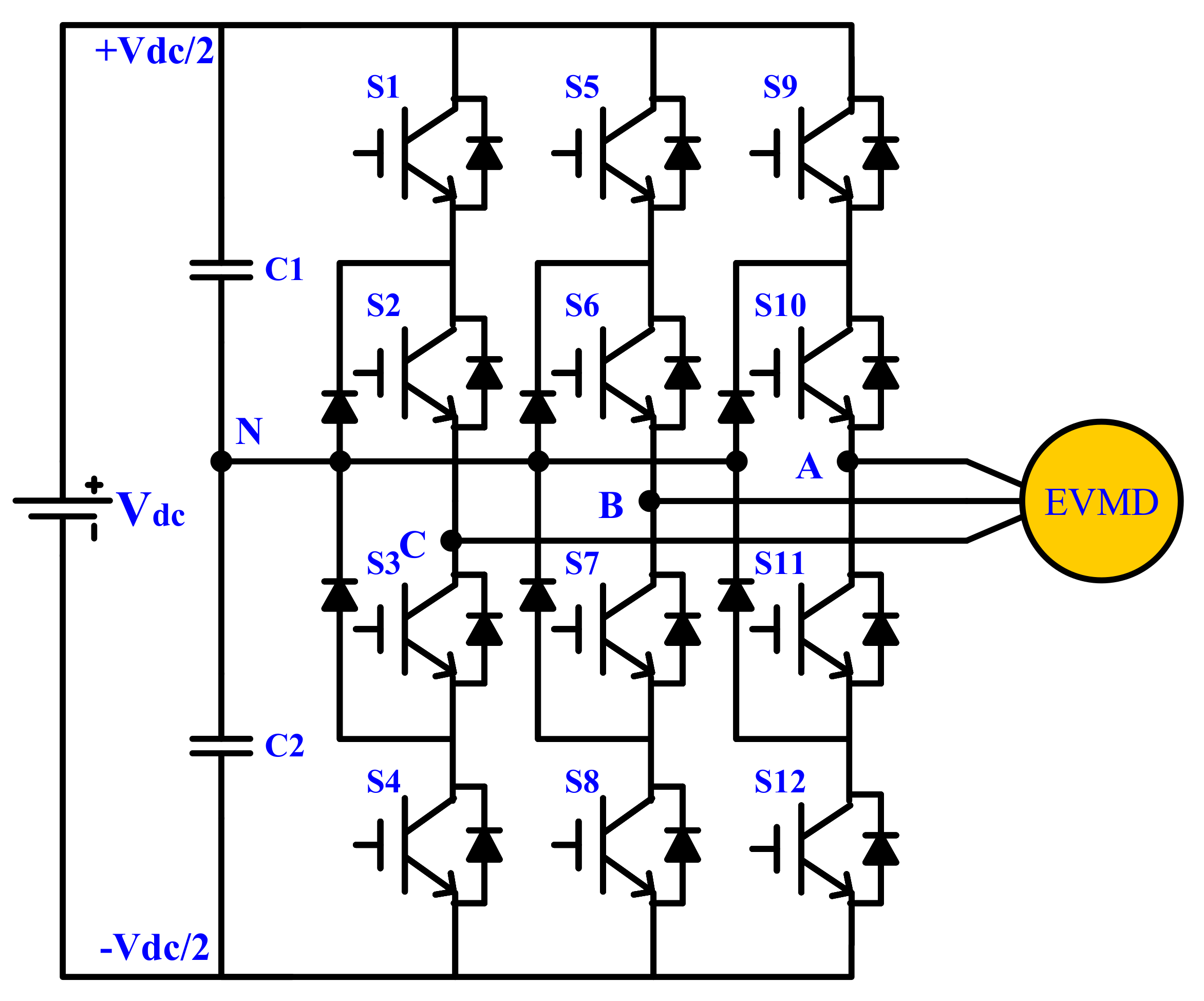
-
Does not require a separate DC supply per bridge leg.
-
A combination of DC-link capacitors could be charged together.
-
Fewer number of switching devices and capacitors as compared with other conventional topologies.
-
The switching losses in the power switches are reduced owing to low switch commutation. Consequently, the efficiency is higher, especially for operation at the fundamental frequency.
-
Reverse recovery problem of clamping diodes; that is, more conduction losses in IGBTs.
-
Switching at the fundamental frequency will cause an increase in the current and voltage THD.
-
Unequal distribution of power losses among semiconductor devices that produce an asymmetrical temperature distribution.
3. Flying-Capacitor Multilevel Inverter
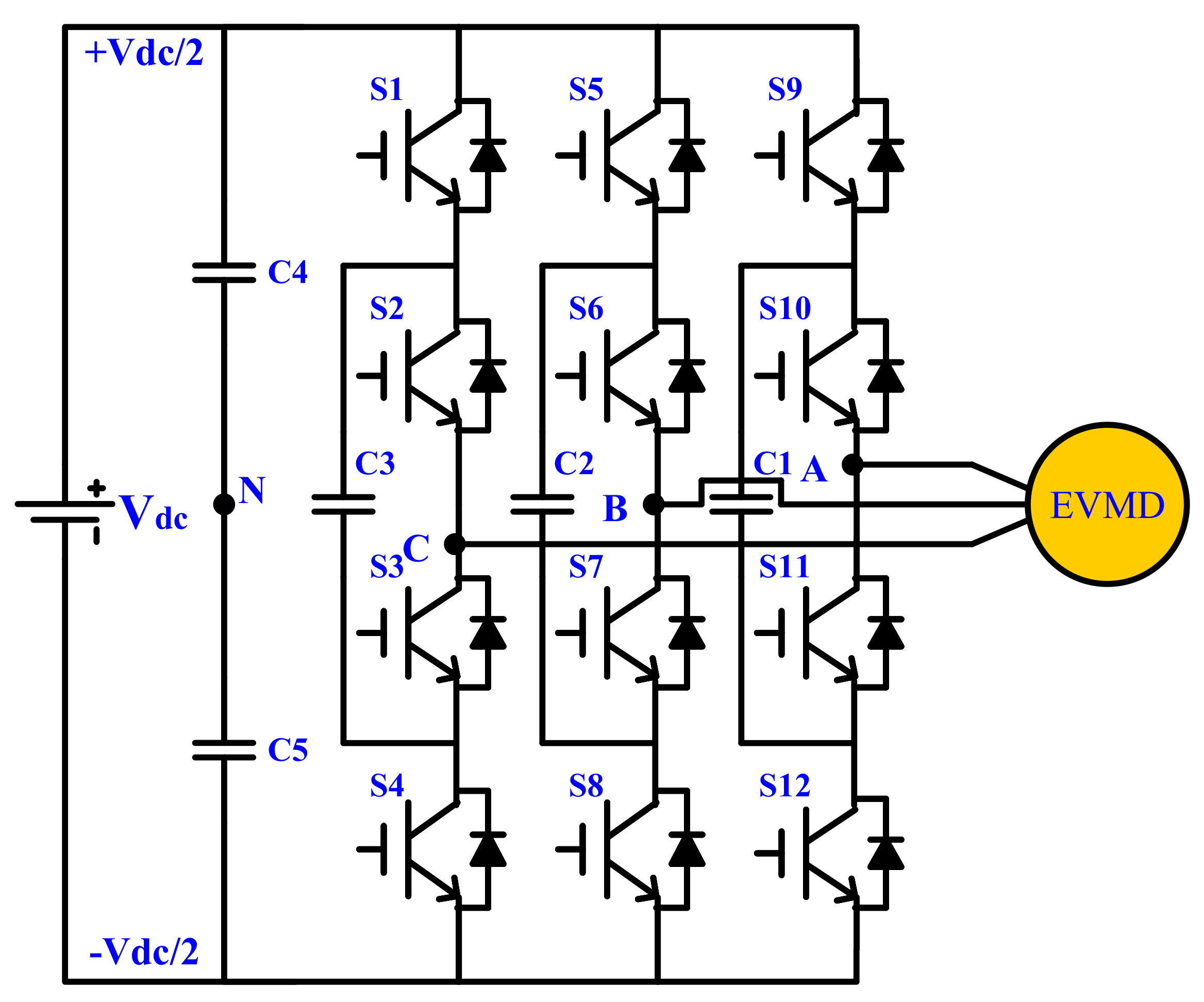
-
Requires only one DC source.
-
The voltage synthesized in FC-MLI has more resilience than a DC-MLI.
-
Ability to control active and reactive power, which can be used for capacitor balancing.
-
A considerable number of clamping capacitors can be used as a capacitor bank that supports a short backup power supply for a short period in the case of short-time power outages.
-
The balancing problem of capacitors.
-
The increase in the level number will impede the correct charging and discharging of the capacitors.
-
Large number of capacitors increase the size and cost of inverter.
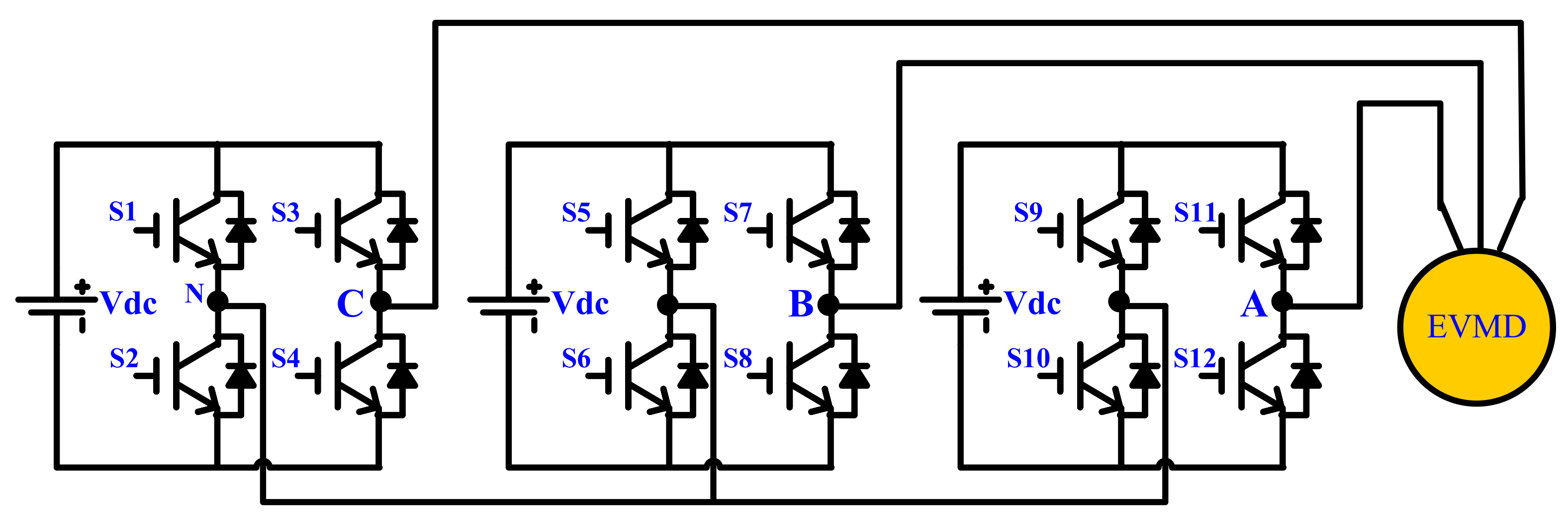
4. Cascaded H-Bridge Multilevel Inverter Topology
| Topology | Number of | ||||||
|---|---|---|---|---|---|---|---|
| DC Voltage Sources |
Switches | Antiparallel Diodes |
Close Diodes |
Capacitors | Balancing Capacitors |
Output Voltage Levels |
|
| DC–MLI | 1 | 12 | 12 | 6 | 0 | 2 | 3 |
| FC–MLI | 1 | 12 | 12 | 0 | 3 | 2 | 3 |
| CHB–MLI | 3 | 12 | 12 | 0 | 0 | 0 | 3 |
-
The number of output voltage levels is equal to twice the number of DC sources plus one (m = 2 s +1).
-
All the power devices operate at the lower switching frequency, resulting in lower switching losses.
-
In CHB–MLI, a low rated-voltage is required for the power switch. This results in a lower dv/dt and lower electromagnetic interference (EMI).
-
To achieve near sinusoidal output voltages with minimum THD, numerous components are required.
-
A high number of voltage levels require many separate DC sources, switching devices, and power diodes to construct the circuit.
References
- Luo, F.; Ye, H. Advanced DC/AC Inverters: Applications in Renewable Energy (Power Electronics, Electrical Engineering, Energy, and Nanotechnology; CRC Press: Boca Raton, FL, USA, 2017.
- Gupta, K.; Ranjan, A.; Bhatnagar, P.; Sahu, L.; Jain, S. Multilevel inverter topologies with reduced device count: A review. IEEE Trans. Power Electron. 2015, 31, 135–151.
- Rodriguez, J.; Lai, J.S.; Peng, F.Z. Multilevel inverters: A survey of topologies, controls, and applications. IEEE Trans. Ind. Electron. 2002, 49, 724–738.
- Kadir, M.; Mekhilef, S.; Ping, H. Voltage vector control of a hybrid three-stage 18-level inverter by vector decomposition. IET Power Electron. 2010, 3, 601–611.
- Axelrod, B.; Berkovich, Y.; Ioinovici, A. A cascade boost-switched-capacitor-converter—Two level inverter with an optimized multilevel output waveform. IEEE Trans. Circuits Syst. I Regul. Pap. 2005, 52, 2763–2770.
- Colak, I.; Kabalci, E.; Bayindir, B.R. Review of multilevel voltage source inverter topologies and control schemes’. Energy Convers. Manag. 2011, 52, 1114–1128.
- Khoshkbar-Sadigh, A.; Dargahi, V.; Corzine, K. New Flying-Capacitor-Based Multilevel Converter With Optimized Number of Switches and Capacitors for Renewable Energy Integration. IEEE Trans. Energy Convers. 2016, 31, 846–859.
- Mecke, R. Multilevel NPC inverter for low-voltage applications. In Proceedings of the 2011-14th European Conference on Power Electronics and Applications (EPE 2011), Birmingham, UK, 30 August–1 September 2011; p. 1.
- Nabae, I.; Akagi, H. A new neutral-point-clamped PWM inverter. IEEE Trans. Ind. Appl. 1981, 5, 518–523.
- De, S.; Banerjee, D.; Gopakumar, K.; Ramchand, R.; Patel, C. Multilevel inverters for low-power application. IET Power Electron. 2011, 4, 384–392.
- Peng, F.; McKeever, J.; Adams, D. Cascade multilevel inverters for utility applications. In Proceedings of the 23rd International Conference on Industrial Electonics, Control and Instrumentation, New Orleans, LA, USA, 14 November 1997.
- Kouro, S.; Malinowski, M.; Gopakumar, K.; Pou, J.; Franquelo, L.; Wu, B.; Rodriguez, J.; Pérez, M.; Leon, J. Recent advances and industrial applications of Multilevel Converters. IEEE Trans. Ind. Electron. 2010, 57, 2553–2580.
- Sayed, K.; Kassem, A.M. Sensorless Vector Controlled Three-Phase PWM Inverter-Fed Induction Motor Drive System With Auto-Tuning Estimation Of Machine Parameter Approach. Sohag Eng. J. 2021, 1, 34–48.
- Rodríguez, J.; Bernet, S.; Steimer, P.; Lizama, I. A survey on Neutral-Point-Clamped Inverters. IEEE Trans. Ind. Electron. 2009, 57, 2219–2230.
- Khomfoi, S.; Tolbert, L. Multilevel Power Converters, Power Electronics Handbook; University of Tennessee: Knoxville, TN, USA, 2007; p. 17.
- dos Santos, C.A.; Antunes, F.L.M. Losses comparison among carrier-based PWM modulation strategies in three-level neutral-point-clamped inverter. In Proceedings of the International Conference on Renewable Energies and Power Quality, Las Palmas de Gran Canaria, Spain, 13–15 April 2011; ICREPQ: Las Palmas de Gran Canaria, Spain, 2011.
- Rodríguez, J.; Bernet, S.; Wu, B.; Pontt, J.; Kouro, S. Multilevel voltage-source-converter topologies for industrial medium voltage drives. IEEE Trans. Ind. Electron. 2007, 54, 2930–2945.
- Joos, G.; Huang, X.; Ooi, B. Direct-coupled multilevel cascaded series VAR compensators. IEEE Trans. Ind. Appl. 1998, 34, 1156–1163.
- Tolbert, L.; Peng, F.; Habetler, T. Multilevel inverters for electric vehicle applications. In Proceedings of the IEEE Workshop on Power Electronics in Transportation, Dearborn, MI, USA, 22–23 October 1998.
- Bendre, A.; Krstic, S.; Meer, J.; Venkataramanan, G. Comparative evaluation of modulation algorithms for neutral point clamped converters. IEEE Trans. Ind. Appl. 2005, 41, 634–643.
- Rashid, M. SPICE for Power Electronics and Electric Power; CRC Press: Boca Raton, FL, USA, 2012.
- Tolbert, L.; Peng, F.; Cunnyngham, T.; Chiasson, J. Charge balance control schemes for a multilevel converter in hybrid electric vehicles. IEEE Trans. Ind. Electron. 2002, 49, 1058–1064.
- Çolak, I.; Kabalci, E. A review on inverter topologies and developments. In Proceedings of the Eleco’2008 Electrics, Electronics and Computer Engineering Symposium, Bursa, Turkey, 26–30 November 2008.
- Purkait, P.; Sriramakavacham, R. A new generalized space vector modulation algorithm for neutral-point-clamped multilevel converters. PIERS Online 2006, 2, 330–335.
- Meynard, T.; Foch, H. Multi-level conversion: High voltage choppers and voltage-source inverters. In Proceedings of the IEEE Power Electronics Specialists Conference, Toledo, Spain, 29 June–3 July 1992.
- Huang, J.; Corzine, K. Extended operation of flying capacitor multilevel inverters. In Proceedings of the Conference Record of the 2004 IEEE Industry Applications Conference, Seattle, WA, USA, 3–7 October 2004; Volume 2004, p. 813.
- He, L.; Cheng, C. A flying-capacitor-clamped five-level inverter based on bridge modular switched-capacitor topology. IEEE Trans. Ind. Electron. 2016, 63, 7814–7822.
- Trabelsi, M.; Vahedi, H.; Abu-Rub, H. Review on Single-DC-Source Multilevel Inverters: Topologies, Challenges, Industrial Applications, and Recommendations. IEEE Open J. Ind. Electron. Soc. 2021, 2, 112–127.
- Xu, L.; Agelidis, V. Active capacitor voltage control of flying capacitor multilevel converters. IEE Proc.-Electr. Power Appl. 2004, 151, 313–320.
- Feng, C.; Liang, J.; Agelidis, V.; Green, T. A multi-modular system based on parallel-connected multilevel flying capacitor converters controlled with fundamental frequency SPWM. In Proceedings of the IEEE 32nd Conference on Industrial Electronics, Paris, France, 6–10 November 2006; pp. 2360–2365.
- Song, B.; Kim, J.; Lai, J.; Seong, K.; Kim, H.; Park, S. A multilevel soft-switching inverter with inductor coupling. IEEE Trans. Ind. Appl. 2001, 37, 628–636.
- Kou, X.; Corzine, K.A.; Familiant, Y.L. Full binary combination schema for floating voltage source multilevel inverters. IEEE Trans. Power Electron. 2002, 17, 891–897.
- Hua, C.; Wu, C.; Chuang, C. Fully digital control of a 27-level cascade inverter with variable dc voltage sources. In Proceedings of the 2nd IEEE Conference on Industrial Electronics and Applications, Harbin, China, 23–25 May 2007; pp. 2441–2448.
- Panagis, P.; Stergiopoulos, F.; Marabeas, P.; Manias, S. Comparison of state of the art multilevel inverters. In Proceedings of the IEEE Annual Power Electronics Specialist Conference PESC ’08, Rhodes, Greece, 15–19 June 2008; pp. 4296–4301.
- Kuhn, H.; Rüger, N.; Mertens, A. Control strategy for a multilevel inverter with non-ideal dc sources. In Proceedings of the IEEE Power Electronics Specialists Conference, Orlando, FL, USA, 17–21 June 2007; pp. 632–638.
- Azli, N.; Choong, Y. Analysis of the performance of a three-phase cascaded h-bridge multilevel inverter. In Proceedings of the 1st International Power and Energy Conference, Putrajaya, Malaysia, 28–29 November 2006; pp. 405–410.
- Du, Z.; Tolbert, L.; Chiasson, J. Reduced switching frequency computed PWM method for multilevel converter control. In Proceedings of the 2005 IEEE 36th Power Electronics Specialists Conference, Dresden, Germany, 16 June 2005; pp. 2560–2564.
- Kocalmis, A.; Sunter, S. Simulation of a space vector PWM controller for a three-level voltage-fed inverter motor drive. In Proceedings of the 32nd Annual Conference of the IEEE Industrial Electronics Society, Paris, France, 6–10 November 2006; IECON: Paris, France, 2006; pp. 1915–1920.
- Hochgraf, C.; Lasseter, R.; Divan, D.; Lipo, T. Comparison of multilevel inverters for static VAR compensation. In Proceedings of the IEEE Industry Applications Society Annual Meeting, Denver, CO, USA, 2–6 October 1994; pp. 921–928.
- Tolbert, L.; Peng, F.; Habetler, T. Multilevel converters for large electric drives. IEEE Trans. Ind. Appl. 1999, 35, 36–44.

