Achieving a soft-switching operation is a challenging task in the development of multilevel inverters for EV motor drives. Nevertheless, multilevel inverters can present several exclusive advantages that are mainly beneficial to EVs. To be exact, they can produce nearby-sinusoidal voltage waveforms with only fundamental frequency, producing smaller harmonic contents in the output current and voltage, reduced power losses, produce almost no EMI, are appropriate for high rating motor drives, and adequate for BEVs where floating DC power sources are logically obtainable. One can overcome the difficulties of the traditional two-level inverter (TLIs), as stated in the previous section. Thus, the expansion of multilevel inverters for EVs can be rapidly accelerated. Multilevel AC output waveforms can be produced by MLI circuit arrangements. Multilevel DC-AC inverters topologies can be classified as classical and advanced inverters.
1. Classical Multilevel DC-AC Inverter (MLI) Topologies
For a better understanding of the new advances in MLI topologies, it is necessary to understand classical MLI topologies, which have been reported in the recent literature
[1][2][1,16]. Three different basic MLI topologies are regularly developed: diode-clamped MLI, flying-capacitors MLI, cascaded H-bridges MLI
[3][4][5][6][7][143,144,145,146,147]. The following summarizes the different types of multilevel inverters:
2. Diode-Clamped Multilevel Inverter Topology
The Diode-Clamped Multilevel Inverter (DC-MLI) topology proposed by
[8][9][10][15,148,149] has been used in several experimental works and published articles
[11][12][13][14][15][16][17][18][19][20][150,151,152,153,154,155,156,157,158,159]. These studies have presented results regarding three-, four-, five-, and six-level DC-MLIs. Another application is high-voltage grid applications, where the PV is the supply power to input the DC-bus in addition to variable-speed motor drives
[1][21][1,14].
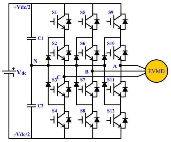
A three-phase three-level Diode-Clamped-MLI topology is displayed in Figure 19. Each of the three-phase inverter outputs shares the DC-bus voltage that has been split into five partitions that are clamped by either of the two extra diodes over four DC bus capacitors. The capacitors are C1 to C4. The two diodes clamp the voltage across the switch to the half level of the DC-bus voltage. The middle points of the C2 and C3 capacitors comprise the neutral point of the inverter, and the output voltage has five voltage values referring to the neutral point. The near AC (multilevel/staircase) output voltage signal is synthesized from some inner voltage levels through a number of switches that are connected in series and switched at a low-frequency control.
Figure 19.
Three-phase three-level diode-clamped multilevel inverter (DC-MLI) for EV motor drive.
The main advantages of the DC-MLI topology are as follows
[1]:
-
Does not require a separate DC supply per bridge leg.
-
A combination of DC-link capacitors could be charged together.
-
Fewer number of switching devices and capacitors as compared with other conventional topologies.
-
The switching losses in the power switches are reduced owing to low switch commutation. Consequently, the efficiency is higher, especially for operation at the fundamental frequency.
-
Reverse recovery problem of clamping diodes; that is, more conduction losses in IGBTs.
-
Switching at the fundamental frequency will cause an increase in the current and voltage THD.
-
Unequal distribution of power losses among semiconductor devices that produce an asymmetrical temperature distribution.
-
3. Flying-Capacitor Multilevel Inverter
The flying-capacitor multilevel inverter (FC-MLI) topology was presented in 1992 as a substitute topology to the DC-MLI in
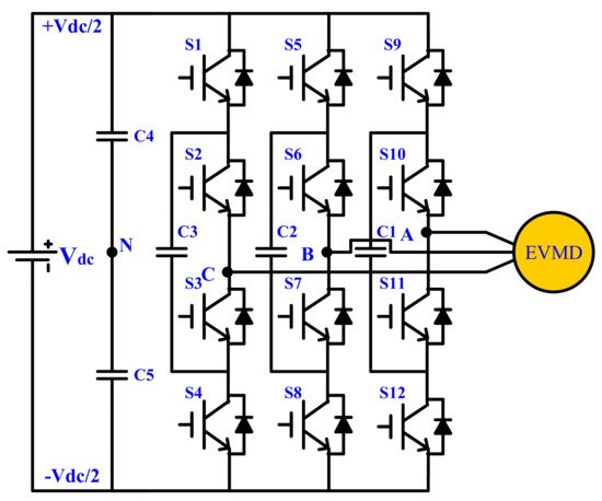
[25][26][27][163,164,165]. A five-level three-phase FC-MLI topology is shown in
Figure 20. The configuration of this circuit is similar to that of DC-MLI, but DC-side capacitors are placed in a ladder form as a replacement for the clamping diodes
[28][29][30][31][166,167,168,169]. The DC-bus voltage is subdivided by a number of capacitors into various voltage levels with a middle neutral point. Consequently, several inner voltage levels exist at different magnitudes, which are clamped by means of clamping capacitors. The multilevel AC voltages of the FC-MLI are synthesized from several levels of inner voltage through several series-connected switches. The associated switches are controlled in a suitable gate-pulse sequence at a proper switching frequency
[12][13][15][151,152,154]. The main advantages of the FC-MLI topology are as follows
[1]:
Figure 20.
Three-phase three-levels flying-capacitor multilevel inverter (FC-MLI) topology for EV motor drive.
-
Requires only one DC source.
-
The voltage synthesized in FC-MLI has more resilience than a DC-MLI.
-
Ability to control active and reactive power, which can be used for capacitor balancing.
-
A considerable number of clamping capacitors can be used as a capacitor bank that supports a short backup power supply for a short period in the case of short-time power outages.
The disadvantages of the FC-MLI topology can be presented as follows
[1]:
-
The balancing problem of capacitors.
-
The increase in the level number will impede the correct charging and discharging of the capacitors.
-
Large number of capacitors increase the size and cost of inverter.
Figure 20 shows the three-phase three-level flying-capacitor multilevel inverter (FC-MLI) topology. The number of voltage-levels, and thus the power quality of the FC-MLI inverter, can be further increased by using the full-binary combination schema
[32][142].
4. Cascaded H-Bridge Multilevel Inverter Topology
A cascaded H-bridge multilevel inverter (CHB-MLI) is an alternative topology for multilevel inverters that require fewer power semiconductor devices as compared with the topologies described earlier. The CHB-MLI topology is based on the number of H-bridges connected in series with separate DC power sources
[33][34][174,175].
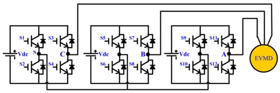
Figure 321 shows a five-level three-phase CHB-MLI topology. Meanwhile, the terminals of the H-bridge output are in series connection, and the DC power sources must be isolated from each other. Because of this attribute, CHB-MLI has also been introduced for renewable energy sources, such as photovoltaic arrays and fuel cell stacks, to interface with the AC power grid
[35][36][37][38][33][170,171,172,173,174], because separate DC sources are required in such applications
[1], to achieve higher levels
[3][35][34][39][143,170,175,176]. Various classical DC-AC inverters are completed in
Table 12.
Figure 321.
Three-phase three-level topology of cascaded H-bridge multilevel inverter (CHB–MLI) for EV motor drive.
Table 12. Comparison of various classical multilevel DC-AC inverters.
| Topology |
Number of |
DC
Voltage Sources |
Switches |
Antiparallel
Diodes |
Close
Diodes |
Capacitors |
| 3 |
2 |
3 |
| CHB–MLI |
-
The number of output voltage levels is equal to twice the number of DC sources plus one (m = 2 s +1).
-
All the power devices operate at the lower switching frequency, resulting in lower switching losses.
-
A high number of voltage levels require many separate DC sources, switching devices, and power diodes to construct the circuit.
In CHB–MLI, a low rated-voltage is required for the power switch. This results in a lower dv/dt and lower electromagnetic interference (EMI).
| Balancing |
|---|
| Capacitors |
Output |
| Voltage Levels |
|---|
| DC–MLI |
1 |
12 |
12 |
6 |
0 |
2 |
3 |
| FC–MLI |
1 |
12 |
12 |
03 |
12 |
12 |
0 |
0 |
0 |
3 |
Comparison of various classical multilevel DC-AC inverters.The main advantages of the CHB–MLI topology are as follows
[1][12][15
The disadvantages of the CHB-MLI topology can be presented as follows
[1]:
A cascaded H-bridge multilevel PWM inverter that comprises four floating DC sources for each phase is shown in
Figure 321. This inverter is not only specialized by the exclusive benefits of multilevel PWM inverters but also by using identical units of the H-bridge inverter, thus improving the manufacturability and modularity of the system
[40][138].
CThe literature review in the previous section presented that conventional multilevel PWM inverter circuits have a special benefit over two-level PWM inverters in terms of low THD, low switching losses, and higher efficiency. While traditional multilevel DC-AC inverters are efficient, they are Suffering from too many components. This increases the overall cost and volume of the inverter and requires a complicated control circuit. Hence, it is important to look at various MLI topologies with reduced components, simpler circuit structure, direct control procedures, and simpler control circuits.