2. In-Process Reinforcement Methods
In-process reinforcement method refers to a reinforcement strategy that allows printing and reinforcing steps to carry on simultaneously and automatically. This highly automated printing system brings benefits to the construction process, for example, by saving the time of applying reinforcement manually. In this way, 3DPC can reach its full potential over conventional concrete construction. However, many of these innovative methods are stagnated at the research stage because they lack the ability to provide high strength improvement to printed concrete, which will be further discussed in the following section.
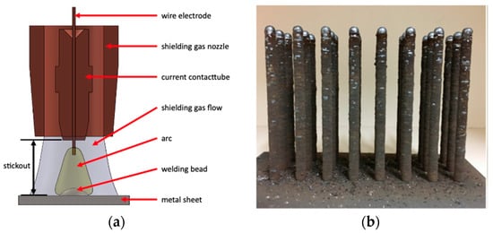
Steel rebar is the preferred and commonly used reinforcement method in conventional concrete construction. Accordingly, it is reasonable to develop strategies for automatic generation and application of steel rebars in the 3D printing of concrete. Mechtcherine et al. [
55] proposed an autonomous system to print steel rebars, a process referred to as gas-metal arc welding (
Figure 8a). In this process, an electric arc between continuously fed wire electrodes and the metal base sheet causes the wire electrode to melt and turn into steel beads, which as it accumulates along the length produces a rebar (
Figure 8b). However, the rationale and the approach of integrating the printing process to include both printed concrete and printed steel rebars are still unsolved. Moreover, the effect of the cooling system required by steel printing on printed concrete and the nature of the interaction of the cooling system with the printing system still need to be determined.
Figure 8. Steel printing concept of generating steel rebars automatically while printing the concrete: (
a) gas-metal arc welding system and (
b) printed steel [
55].
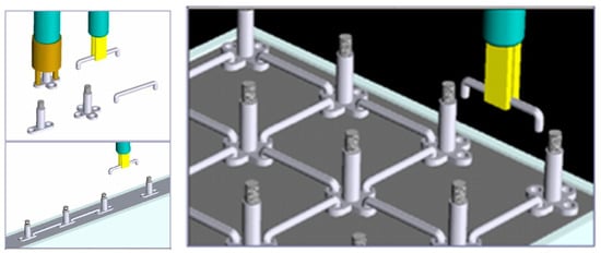
Khoshnevis [
28] designed a novel reinforcement method to add reinforcement during the Contour Crafting printing process. The steel reinforcement used here consists of many small steel elements (
Figure 9), which can be assembled to form different shapes (strip and mesh). The printing process is operated by a gantry system that contains a nozzle for printing the shell, a robot for assembling steel elements, and a feeder for filling the formwork with concrete. However, the complexity of this expensive and intricately detailed printing system makes it a challenge to apply in actual construction.
Figure 9. Steel elements reinforcement for printed concrete developed by Khoshnevis [
28].
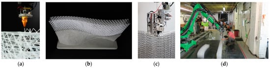
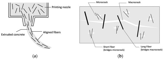
Another method that can combine printing and reinforcing processes in 3DPC is fiber reinforcement (
Figure 10a), also called discontinuous reinforcement. Short fibers that will easily flow through the pump’s stator and nozzle with concrete are mixed with other ingredients until reaching uniform consistency throughout and then extruded as fresh concrete to generally enhance shear, compression, and tensile resistance of the printed and cured concrete. Hambach and Volkmer [
72] reinforced 3D printed concrete in small scale (specimen size is about a few centimeters) using carbon, glass, and basalt fibers (3–6 mm in length, 7–20 μm in diameter). The diameter of the nozzle was adjusted to be 2 mm, which is smaller than the lengths of fiber to make sure the extruded fibers aligned with the printing direction. Such a small diameter nozzle is not commonly used to print concrete, but it is feasible to do this without mixing aggregate in the cement mixture. The high degree of aligned fibers increases the flexural and compressive strength of printed concrete, reported to reach 30 MPa and 82.3 MPa, respectively, as the maximum value among tested specimens. A similar concept but with different materials was used by Bos et al. [
73] where steel fibers (6 mm) with 2.1 vol% were added to the wet concrete mix and extruded with concrete parallel to the nozzle travel direction. The experiment recorded a significant increase in the flexural strength of printed concrete after adding steel fibers (from 1.1 to 5.95 MPa). Additionally, adding multiple lengths of steel fibers (6 mm and 13 mm) in the concrete mix (
Figure 10b) has been considered and experimented with at Technical University at Eindhoven (TU/e), Netherlands, to improve the mechanical properties of printed concrete under loading conditions [
74]. Accordingly, 6 mm fibers can bridge microcracks increasing tensile strength, and 13 mm fibers can hold the macrocracks, increasing the ductility after cracking. Although this printing system seems useful to help 3D printing reach its full potential for automation, there is still room for improvement. The highest level of strength achieved using this approach is still not enough to build large-scale concrete elements without additional reinforcement, which may be feasible with some of the other types of reinforcement, thereby pushing the strength limit further. The orientation of fibers need not necessarily be aligned with the nozzle as multi-directional fibers can become feasible by enlarging the nozzle diameter, which is more suitable to increase the overall performance of concrete, including but not limited to flexural, compressive, and shear resistance.
Figure 10. Fiber reinforcement for printed concrete: (a) schematic diagram of printing concrete with fibers and (b) functions of fibers in different lengths.
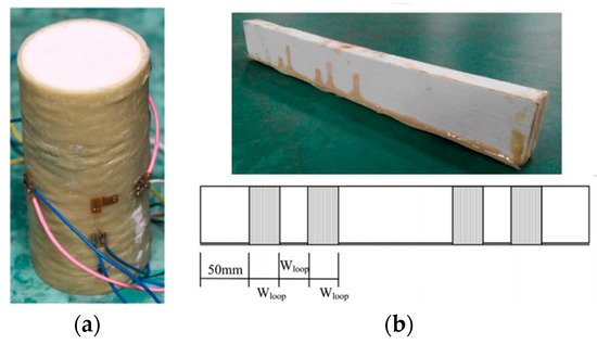
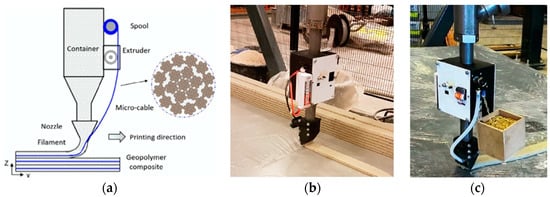
Different from discontinuous reinforcement, continuous reinforcement is input at the nozzle. Continuous steel micro-cable reinforcement has been applied in 3DPC by Ma et al. [
75] (
Figure 11a). The dual printing system consists of a nozzle for printing concrete and an extruder for placing steel micro-cable driven by a step motor that can continuously feed the steel micro-cable (1.2 mm diameter) to the printing nozzle. The feeding speed is adjustable to print concrete and lay steel micro-cable synchronously and to embed steel micro-cable into concrete beads while printing. The maximum flexural strength of the steel micro-cable reinforced concrete is reported to be 30 MPa, which corresponds to the maximum flexural strength of the short fiber reinforced concrete (30 MPa) based on Hambach and Volkmer’s research [
72] mentioned in the previous paragraph. This similarity implies the range of flexural strength of printed concrete reinforced by filament reinforcements, i.e., fibers and micro-cables. Additionally, it highlights the need for multiple reinforcements and the need for new reinforcement strategies.
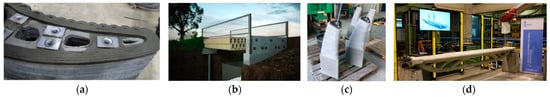
Figure 11. Concrete printing systems for different types of continuous reinforcement: (
a) continuous steel cable [
75], (
b) wire rope [
77], and (
c) steel chain [
77].
A similar printing system but with different continuous reinforcement has been discussed by Jutinov [
76] and Bos et al. [
77]. Jutinov claimed that wire rope (
Figure 11b) is more suitable to use as a reinforcement than steel chain (
Figure 11c) and steel wire because it has high flexibility in the transverse direction, making it easier to work with, in particular for curve-shaped walls.
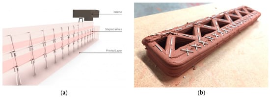
Instead of being printed together with fresh concrete, steel reinforcements can also be stapled into printed concrete. Geneidy and Kumarji [
78,
79] experimented with this innovative idea where the refitted electrical staple gun bonded to the robot arm inserts staple-like steel wire profiles (
Figure 12a,b) into fresh concrete in designed locations. The stapling process is continuous with the movement of the robot arm and is accomplished simultaneously with concrete printing. Different shapes of steel wire are available for different geometric situations. After printing, the staples are embedded in concrete to form a 3D wire mesh, which not only enhances the bonding between printed layers but also increases the whole structural integrity. Accordingly, the most significant advantage of this printing system is that steel profiles can be stapled in different patterns by the staple gun with a switch that triggers the firing mechanism during the printing process. To be more specific, steel wire profiles can be inserted and overlapped to each other as an “X” shape (
Figure 12b) between parallel beads to provide interlocking force or applied at the corner to strengthen that weak area. As suggested by the authors, future work includes using machine learning to simplify the process of locating weak points, identifying proper reinforcement types, and developing an optimized printing process. Although the amount of reinforcement based on this technique is still much below the steel rebar, high flexibility and controllability make it worth considering for reinforcing 3D printed concrete.
Figure 12. Applications of steel wire profile reinforcement in printed concrete: (
a) aligning with printing direction [
78] and (
b) applied in “X” shape [
79].
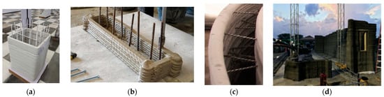
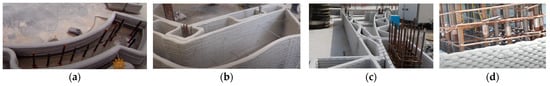
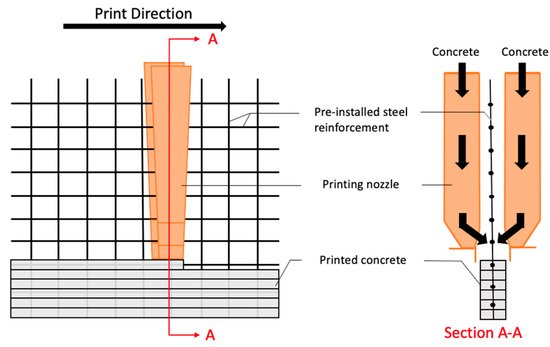
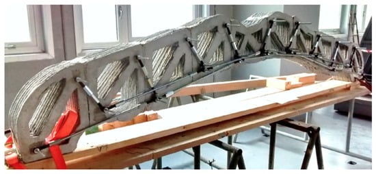
Steel mesh reinforcement commonly used in conventional concrete is typically embedded horizontally at mid-depth of the concrete slab. Marchment and Sanjayan [
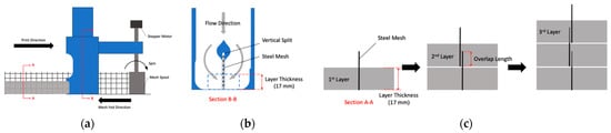
80] proposed a novel way to embed steel wire mesh vertically in 3DPC while printing concrete walls. Accordingly, the steel wire mesh is rolled and placed vertically onto a spool, from which it is fed as the nozzle travels controlled by a stepper motor (
Figure 13a). The nozzle head has a vertical split in the middle and is positioned after the spool along the travel direction to allow the placed vertical mesh to pass through the vertical split (
Figure 13b). Inside the nozzle, the flow of fresh concrete is separated by that split but merged in the middle when the concrete is printed on both sides of the mesh. With these settings, a vertical mesh can be applied simultaneously with concrete during printing and sided by concrete beads on both sides to keep it vertical. The mesh is higher than the layer thickness (17 mm) but lower than two layers (34 mm) to overlap in the vertical direction among layers and achieve continuity in the vertical direction (
Figure 13c). After the failure test (flexural bending test), steel yielding occurs before bond failure, which proves the existence of enough bond strength between the concrete and the steel wire mesh and that the embedded steel mesh contributes to the flexural bending resistance. This printing system has great potential as it is the first method to add vertical mesh automatically along with concrete printing. On the other hand, because the steel wire mesh segments are not welded or tied in the vertical direction and the customized feeding system limits the rigidity of the steel mesh, the increased flexural strength using this reinforcement method will be much less than applying a whole piece of welded wire mesh manually. Additionally, the author recommends cutting the mesh for different layer printing, but after cutting, it would be hard to align the wire to the nozzle head notch without manual interference. Furthermore, the mesh should be very flexible to roll in the spool, which has less stiffness than the steel rebar. These concerns need to be further addressed and improved to reach the full potential of this printing system.
Figure 13. Vertically placed steel wire mesh reinforcement for printed concrete: (a) placement of vertical steel mesh reinforcement, (b) cross-section of nozzle head, and (c) overlapping of vertical steel mesh between printed layers.
 +1 credit