Submitted Successfully!
To reward your contribution, here is a gift for you: A free trial for our video production service.
Thank you for your contribution! You can also upload a video entry or images related to this topic.
Version Summary Created by Modification Content Size Created at Operation
1 + 5490 word(s) 5490 2022-01-11 09:05:04 |
2 format corrected. -2 word(s) 5488 2022-01-24 07:53:31 |

Video Upload Options

Do you have a full video?

Confirm

Are you sure to Delete?
Cite
If you have any further questions, please contact Encyclopedia Editorial Office.
Sharry, T. Finite Element Modelling and Updating of Cable-Stayed Bridges. Encyclopedia. Available online: https://encyclopedia.pub/entry/18681 (accessed on 14 September 2024).
Sharry T. Finite Element Modelling and Updating of Cable-Stayed Bridges. Encyclopedia. Available at: https://encyclopedia.pub/entry/18681. Accessed September 14, 2024.
Sharry, Thomas. "Finite Element Modelling and Updating of Cable-Stayed Bridges" Encyclopedia, https://encyclopedia.pub/entry/18681 (accessed September 14, 2024).
Sharry, T. (2022, January 24). Finite Element Modelling and Updating of Cable-Stayed Bridges. In Encyclopedia. https://encyclopedia.pub/entry/18681
Sharry, Thomas. "Finite Element Modelling and Updating of Cable-Stayed Bridges." Encyclopedia. Web. 24 January, 2022.
Finite Element Modelling and Updating of Cable-Stayed Bridges
Edit

Finite element (FE) model updating is a well-recognised approach for Structural Health Monitoring (SHM) purposes, as an accurate model serves as a baseline reference for damage detection and long-term monitoring efforts. One of the many challenges is the development of the initial FE model that can accurately reflect the dynamic characteristics and the overall behaviour of a bridge. Given the size, slenderness, use of long cables, and high levels of structural redundancy, precise initial models of long-span cable-stayed bridges are desirable to better facilitate the model updating process and to improve the accuracy of the final updated model. To date, very few studies offer in-depth discussions on the modelling approaches for cable-stayed bridges and the methods used for model updating. As such, this article presents the latest advances in finite element modelling and model updating methods that have been widely adopted for cable-stayed bridges, through a critical literature review of existing research work.

cable-stayed bridge structural health monitoring finite element modelling model updating

1. Finite Element Modelling of Cable-Stayed Bridges

1.1. General Bridge Modelling Approaches

A background of general bridge FE modelling is presented first, as progressive developments over the last 30 years have influenced the modelling approaches for cable-stayed bridges. The seminal work by Hambly [1] covered the numerical modelling of a range of short to medium highway bridges. Though long-span cable supported bridges were not covered, it is worth mentioning some early suggestions for beam, deck slab, and box girder bridge modelling in this text. Firstly, skeletal models are sometimes preferred due to limited monitoring data and measurement points as a guide to identifying the magnitudes and directions of forces and displacements. Secondly, grillage analysis in 2D by modelling the girders using longitudinal beam elements and intermediate diaphragms within the span using transverse beam elements is a reliable way to model the bridge deck. Lastly, truss space frame analysis using beam elements in three-dimensions and equivalent sectional properties is best used for modelling global bridge behaviour. In terms of model resolution, Kanok-Nukulchai et al. [2] presented three levels of cable-stayed bridge modelling techniques ranging from the lowest resolution level using line elements for global behaviour, to finer 2D or 3D elements used for local analysis. Similarly, Walther [3] used the categories of: (i) Plane frame models, which are a simplified, 2D projection of the whole structure onto a plane where all the structural members are represented by beam elements; (ii) Space frame models, which are represented with beam elements in three dimensions; and (iii) Partial models, which are 3D models used to examine local problems with more detail with the possible use of solid elements. Walther suggested representing the deck and towers of cable-stayed bridges with beam elements, or the deck with shell elements, depending on the complexity of the bridge and the stage of the design. Fu and Wang [4] stated that the deck can be modelled as a beam when the ratio of length to width of the whole bridge is so great that the applied loads typically cause the bridge to bend or twist along its length while the cross section does not change shape. Fu and Wang also suggested plane frame models or a grillage model of longitudinal and transverse beams for the deck when a more refined analysis is needed later in the design stage. More recently, the AASHTO Manual for Refined Analysis in Bridge Design and Evaluation [5] outlined the differences in 1D, 2D, and 3D models as a way of describing the level of refinement of bridge analyses. While 1D and 2D models were deemed efficient choices for straight multi-girder or torsionally stiff box girder beam bridges where lateral and torsional responses are not critical, 3D models were recommended only to the extent that they remain computationally efficient. The AASHTO Manual [5] concluded that in many cases the improved accuracy offered by 3D models were insignificant and unworthy of the additional computation effort. Furthermore, for most typical concrete slab on girder bridges, combined plate and line elements for the deck and girders, respectively, were recommended.
Xu [6] and Xu and Xia [7], building on the work in Xu et al. [8] of an FE model of the Tsing Ma suspension bridge in Hong Kong suggested two approaches to modelling. The first was a simplified spine-beam model of equivalent sectional properties which captures the global dynamic behaviour without heavy computational effort. Five key features of this approach are: (i) The use of line elements including beam elements, truss elements, and rigid links for modelling cable-supported bridges; (ii) Pylons and piers are usually modelled with beam elements based on their geometric properties; (iii) Cables are often modelled by truss elements, and their geometric non-linearity due to cable tension is taken into consideration by the Ernst formula [9]; (iv) The bridge deck is the most challenging to model. The most common approach to simplify the complications of the deck is to model the deck as a central beam or a series of beam elements; (v) The equivalent cross-sectional area of the deck is calculated by summing up all cross-sectional areas. In the case of a composite section, the areas should be converted to that of one single material, according to the modular ratio of two materials; (vi) Constraints are modelled using spring elements, rigid links, or direct coupling of nodal displacements. These are necessary to connect different parts of the model together and to enforce certain types of rigid-body features. For example, if the nodes of the deck, bearings and tower do not coincide with each other, rigid links are usually used to restrain their motions in different directions. Rigid links are also used to connect the spine beam with cables. The second approach from Xu [6] and Xu and Xia [7]  was referred to as a hybrid model or multi-scale model that utilises a combination of different types of elements in the same model, i.e., line, shell, solid, to capture finer details in an area of interest, although care must be taken at the interface between these different elements due to incompatible degrees of freedom. A typical approach would be to use plate or shell elements to model the deck and beam elements for towers and piers. Gazzola [10] and Bas [11] concurred with these two approaches when modelling suspension bridges.
By contrast, Pipinato [12] presented different modelling strategies to investigate specific problems of bridge structures. Global models are used for global static and dynamic analyses. Local models are partial models used to amplify the structural behaviour at a higher scale. Tension and compression models are used to capture nonlinear responses of bridges with expansion joints in order to model the nonlinearity of the hinges with cable retainers. Frame models treat the piers and deck from a side view as a frame. Pipinato [12]  further recommended for modelling cable-stayed bridges in three-dimensions in that: (i) the main girder was modelled as a spine beam with perpendicular rigid links connecting the spine to the cable anchor points; (ii) 3D beam elements were used for towers and piers; (iii) truss elements were used for cables unless there is a cable element available in the modelling package; and (iv) the tower/girder connection was introduced into the model according to the specific connection (full separation, rigid connection, vertical support, etc.).
It is apparent from the information offered by the literature that there are recurring themes common to FE modelling efforts regardless of the bridge types. The literature makes several common and clear distinctions in bridge deck modelling: (i) The spine beam or single-girder method which uses a single line beam element or series of line beam elements to represent the bridge deck and piers. This simplified geometry helps in identifying the global behaviour of the model. As early as the 1980s, beam theory was used to model the behaviour of thin-walled box girder bridges [13][14]. Wilson and Gravelle [15] were among the first to present a full single-girder model for a cable-stayed bridge with rigid links used to connect the central spine beam to the two outer planes of cables. (ii) The next level of bridge modelling, referred to as a grillage model, involved the separation of the single spine beam into two or more longitudinal spine beams, connected by transverse beams in the perpendicular direction. This too identifies the global behaviour with more details of local behaviour in the deck such as deformations and torsional behaviour as a result of the grillage formation. Work by Zhang [14] explored grillage idealisation of multi-spined box girders, and Yiu and Brotton [16] made first use of a double-girder model for a cable-stayed bridge. Cheng et al. [17] was one of the earliest works that compared the performance of a double-girder FE model of a cable-stayed bridge with a triple-girder model. Zhu et al. [18] shortly followed with a triple-girder model of a cable-stayed bridge. (iii) The multi-scale or hybrid modelling approach introduces 2D and/or 3D elements in conjunction with line elements. A typical configuration utilises 2D plate elements for the deck with line beam elements for the pylons and cables. Early multi-scale modelling of cable-stayed bridges is found in Brownjohn et al. [19]. (iv) The last modelling approach fully utilises 2D and 3D elements to construct the model or, more realistically, to model a part of the bridge where local stress/strain information is required.

1.2. Cable-Stayed Bridge Modelling Approaches

Several space frame models consisting of line elements to model cable-stayed bridges have been offered by the literature [2][18], in an attempt to reduce the degrees of freedom and simplify the dynamic analysis. These models are distinguished from each other depending on how the deck has been modelled: single-girder, double-girder, triple-girder, or multi-scale. Each will be discussed in the following subsections.

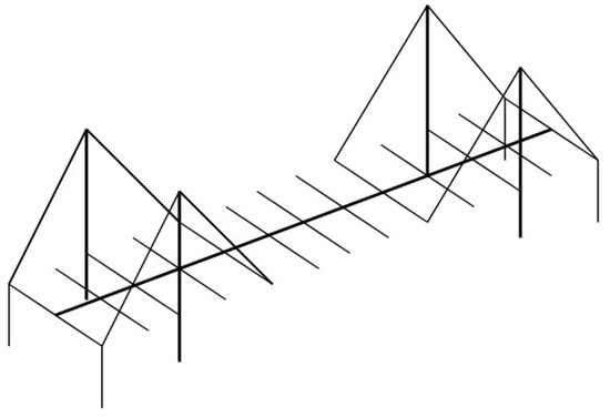
1.2.1. Single-Girder Modelling

The spine beam or single-girder model (Figure 1) is the most common and most likely the earliest three-dimensional FE model for cable-stayed bridges in structural dynamics using perpendicular rigid links to accommodate the cable anchor points [20]. The deck stiffness is assigned to the spine beam, and lumped masses assigned to the spine nodes. The accuracy of single-girder models is particularly questionable when representing the bridge deck system in lateral and torsional vibration modes. The lateral modes in particular may be distorted to some extent if the deck stiffness equivalence is treated improperly [21]. Additionally, cable-stayed bridges are normally subjected to high levels of torsion under which plane sections may no longer remain plane, resulting in large torsional warping. Open deck sections are more likely to experience this than closed sections. Criticisms offered by Zhu et al. [18] and Ren and Peng [20] indicate that a single-girder model neglects transverse beam stiffness and girder warping and is more suited for box section girders with relatively large pure torsional stiffness but small warping stiffness. For cable-stayed bridges with double cable planes and an open-section deck, the pure torsional stiffness may be small, and the warping stiffness may become critical for the dynamic analysis of the bridge.
Infrastructures 07 00008 g002 550
Figure 1. Spine-beam or single-girder model.
An early technique of taking warping stiffness of the bridge deck into account in a single-girder model was offered by Wilson and Gravelle [15]. This study introduced an equivalent pure torsional constant by assuming that torsional mode functions are sine functions which are assigned to the bridge deck. In this study, an open section girder was simulated by treating the deck stiffness and deck mass separately. By dividing the lumped masses to either side of the deck, the rotation effect of deck mass was included. To simulate the eccentricity between the center of rigidity (the stiffness centroid of the deck girder against lateral forces) and the center of mass of the deck, the deck mass was placed below the axis of the deck spine using vertical rigid links. This produced coupling between torsional and transverse motions of the deck. A slight modification of this modelling technique was presented by Dyke et al. [22] where the rigid links were connected to the single-girder in an ‘X’ shape due to the actual construction of the bridge where the attachment points of the cables to the deck are above the neutral axis of the deck. A comparison between assigning lumped masses to the central spine beam and assigning lumped masses to the sides and keeping the spine beam massless was conducted by Caicedo et al. [23]. While vertical vibration modes were not significantly affected, torsional frequencies were lowered significantly in the model with lumped masses on the sides and showed a slight increase in the first lateral mode.
Examples from the literature include Schemmann and Smith [24] and Caetano et al. [25] who modelled the Jindo Bridge in South Korea, having A-shape towers and a box girder deck. Both studies used the single-girder method, and attached lumped masses along the central spine and at the ends of each rigid link. Whereas Schemmann and Smith [24] investigated non-linear behaviour and complexities associated with modelling cable-stayed bridges, Caetano et al. [25] compared the model’s dynamic results by changing the number of elements in the stay cables to a physical model of the bridge which was excited by an electrodynamic shaker in shaking table tests. Schemmann and Smith [24], however, did not compare the model’s results with any data, it is therefore uncertain as to how effective the modelling approach was. For Caetano et al. [25], an approximate correlation was established between the physical and numerical models. The Oshima Bridge, also with A-shape towers and box girder deck, was modelled by Wu et al. [26] as a single-girder model with single and multiple elements used to model the stay cables, in a similar fashion to Caetano et al. [25]. The stay cables were discretised into 16 truss elements to study local parametric (secondary) vibrations in the cables. The only results used to validate the model were analytically derived cable natural frequencies that were compared with the cable vibrations identified from the model. The results showed good correlation. Chang et al. [27] modelled the Kap Shui Mun Bridge, having H-shape towers and box girder deck section, using a single-girder with lumped masses on the spine to identify dynamic characteristics. Comparison with field measurements correlated well with 31 vibration modes identified and the largest frequency difference was 28%, attributed to modelling errors, vibration measurement and postprocessing errors, or both.
Caicedo et al. [23] and Dyke et al. [22] modelled the Bill Emerson Memorial Bridge having H-shape towers and an open section girder with transverse beams. Caicedo et al. [23] compared two FE models for the purpose of dynamic analysis of this cable-stayed bridge. The first model used the single-girder method with lumped masses along the central spine, and the second model also used the same method but with the lumped masses attached to the sides and below the centroid of the deck to compare the difference in torsional frequency. Dyke et al. [22] later used the second model with lumped masses to the sides for a benchmark structural control problem. The second model gave lower torsional frequencies indicating that lumped masses along the central spine gives a torsionally stiffer model. As the bridge was under construction at the time, Dyke et al. [22] could not validate these results against measured data. A study by Song et al. [28] identified the first five vibration modes of the same bridge which, when compared to the results of Caicedo et al. [23], show an average percentage different of 4% between the first five modes. Domaneschi et al. [29], improving upon the model of the Bill Emerson Memorial Bridge by Caicedo et al. [23], used a multi-scale model with shell elements for the deck and multi-element cables to improve the modelling of the stay-deck coupled response. As the study focussed on damage in the stay cables, global vibration modes were not identified, and the model was not validated. Lin and Lieu [30] modelled the Kao Ping Hsi Bridge, consisting of a single cable plane, an A-shape tower, and a box girder section, using a single line girder for investigating the effects of geometric nonlinearities on the buffeting response of the bridge. The study was purely numerical and therefore was not validated against experimental results, however the study did find that geometric nonlinearities of cable-stayed bridges, which are generally ignored, become significant with increasing wind velocity.

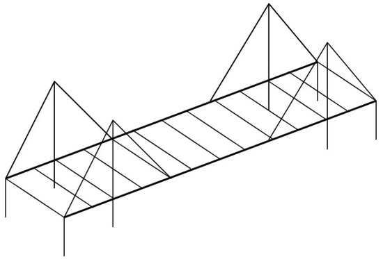
1.2.2. Double-Girder Modelling

For cable-stayed bridges with double cable planes and an open-section deck, a double-girder model, i.e., two longitudinal edge beams in line with each cable plane connected by transverse rigid links (Figure 2), seems to represent the system most naturally, however with no center spine beam, the deck stiffness and mass are distributed to both longitudinal edge beams which may not represent the true behaviour of the deck. The warping stiffness of the bridge deck can be considered through the asymmetrical vertical bending stiffness of the two side girders.
Infrastructures 07 00008 g003 550
Figure 2. Double-girder model.
Nazmy and Abdel-Ghaffar [31] successfully applied this approach to the analysis of long-span cable-stayed bridges. The double-girder treatment can lead to uncertainties however in the equivalence of the warping stiffness with the vertical bending stiffness, as the latter is also taken by the stiffness of the two girders if the transverse links are rigid and provide no section properties [18]. Attempting to avoid this issue by modelling the transverse links as elastic members contributing to the sectional property of the deck leads to increased computation time. This is because the equivalence of the vertical, lateral and torsional stiffnesses will be difficult to execute. An uncommon approach to consider warping effects is to use thin-walled elements to model the bridge deck. Thin-walled cross sections can be modelled using plate, shell or three-dimensional elements to fully capture its dynamic behavior. However, this modelling approach is not generally recommended due to computational costs and has only been suggested in the literature . Applications of double-girder models are not common in the literature with Asadollahi et al. [32] being the most recent example. As mentioned, the absence of a center spine beam can create problems, as the stiffness and mass distribution can only be assigned to the edge beams, leading to a distortion of torsional and vertical bending modes. A more popular method is to include a centered longitudinal beam with two longitudinal edge beams.

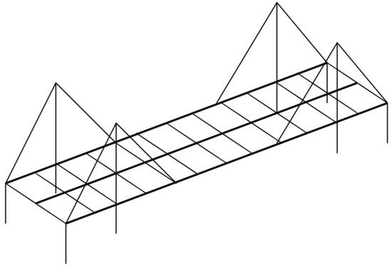
1.2.3. Triple-Girder Modelling

The warping stiffness of open-section decks is one of the most challenging parameters to estimate in developing a model for cable-stayed bridges [20]. To overcome the limitations in previous models, Zhu et al. [18] presented a triple-girder model consisting of one central girder and two side girders in an attempt to include warping stiffness while modelling the Nanpu cable-stayed bridge having a H-shape tower and open section girder with transverse beams. Zhu et al. [18] compared two FE models. The first model used the single-girder method with lumped masses along the central spine. The second model used the triple-girder method and distributed the mass and sectional properties across the three girders. The higher torsional stiffness of the triple-girder model increased the lateral and torsional frequencies compared to the single-girder model, with the vertical and longitudinal modes staying roughly the same. The triple-girder model was found to be in better agreement with the measured results than the results from the single-girder model. In particular, the warping effect of the bridge deck was better considered using the triple-girder model. Torkamani and Lee [33] in a dynamic study of an arch bridge showed that the first lateral frequency of a double-girder model is half that of a triple-girder model with noticeable differences between torsional frequencies as well. Similarly, Hu et al. [34] modelled the Owensboro Bridge with A-shape towers and an open section composite deck using the triple-girder approach. The initial model was calibrated by changing certain material properties of the girders and towers to correlate well with experimental modal properties derived from free vibration test results. Out of the six modes identified from the test results, all achieved some correlation regarding frequencies and one of these modes disagreed with the mode shape (vertical mode from the test results and torsion mode from the model). The limitations of the free vibration test meant that higher modes and some lower modes were not able to be compared with the FE model, and from the results, the six modes were vertical modes only. No lateral or torsional modes were correlated which was a major limitation of the study by Hu et al. [34]. The most obvious disadvantage of the triple-girder approach (Figure 3) is the assignment of the girder properties—mainly the geometric and material properties, along with the non-structural mass distribution between the three longitudinal beams. This adds an additional dimension of complication that can be avoided by using the single-girder method. Furthermore, despite the potential of the triple-girder model to give greater behaviour prediction accuracy, single-girder models still dominate the literature, suggesting that solution accuracy and computational time of single-girder models are more favourable.
Infrastructures 07 00008 g004 550
Figure 3. Triple-girder model.

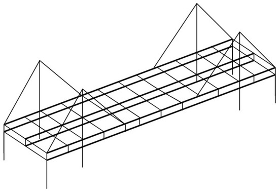
1.2.4. Multi-Scale Modelling

The most common multi-scale model, or finite element combination, of cable-stayed bridges is generally line elements for the piers, towers, and cables, and shell, plate, or brick elements for the deck (Figure 4). For multi-scale modelling efforts, Ren et al. [35] and Ren and Peng [20] found that the stiffness contribution of shell elements representing the concrete slab on a steel arch bridge and a cable-stayed bridge, respectively, had little effect on the vertical bending stiffness but contributed greatly to increase the lateral and torsional stiffness of the bridge deck. Park et al. [36] showed that the use of shell elements for the deck of a cable-stayed bridge produce a higher frequency for the first lateral vibration mode, which was closer to the measured frequency.
Infrastructures 07 00008 g005 550
Figure 4. Multi-scale model with deck plate elements.
For comparison purposes, Brownjohn et al. [37] modelled the Safti Link Bridge having single central cable plane, single I-shape tower and box girder deck using two models; a single-girder model and a multi-scale model using shell elements for the deck. A dynamic assessment showed that the multi-scale model performed much better and that condensing the properties of the deck into a single girder was inappropriate. Given that the Safti Link Bridge is 100 m in length and curved with a single tower, a more detailed model may be more appropriate as illustrated in this case. In another comparative study, Ren and Peng [20] modelled the Qingzhou Bridge with A-shape towers and an open section deck by comparing a triple-girder model and a multi-scale model for a baseline FE model. The triple-girder model distributed the mass of the concrete deck across the three girders, while the multi-scale model used shell elements for the concrete deck. The results showed significant difference in lateral and torsional vibration modes with the shell elements increasing the stiffness for both lateral and torsion modes. Upon comparison with experimentally identified frequencies, the multi-scale model showed superior correlation. Macdonald and Daniell [38] also modelled an open section deck and H-shape towers of the Second Severn Crossing using a multi-scale model: shell elements for deck, and beam elements for girders and transverse beams. This model was used to identify variations in modal parameters from ambient vibration measurements and FE modelling. Compared with ambient vibration results, the maximum frequency difference was 11.6% with an average of 4.3% difference across 23 modes indicating a good correlation. The torsional/lateral modes show good correlation suggesting the accuracy of multi-scale modelling without any need of updating in this case. Similarly, Zhong et al. [39] modelled the Guanhe Bridge, also having H-shape towers and an open section deck, using a multi-scale model and a single-scale model to propose a new methodology for FE model validation. The single-scale model used 3D solid elements for the towers and deck, and 3D shell elements for the girder. The multi-scale model used beam elements for the towers and central girder, while the edge girders were modelled with 3D solid elements. In one of the few studies to include model run time, the multi-scale model took approximately 5 min while the single-scale one took almost 4 h. The updated multi-scale model was compared with ambient vibration results with a maximum relative error of 7.8% for a total of 7 vertical, transverse, torsion, and longitudinal modes. The multi-scale model used in Zhong et al. [39] was essentially a triple-girder model, with the edge girders as solid elements. The results were comparable with the single-scale model at a fraction of the run time. The multi-scale model differs from what is normally offered in the literature, (usually shell elements for the deck) in this case the edge girders are solid elements and the masses distributed as per a triple-girder approach. This method offers a new alternative to both multi-scale and triple-girder approaches. Abozeid et al. [40] modelled the Suez-Canal Bridge having H-shape towers and a variable box girder section with a multi-scale model as a candidate for model updating. The study mentioned that pylons, piers and cables were modelled using beam elements. Shell elements were used for the main girder. The model results were found to be lower when compared to experimental modal analysis results indicating the model stiffness was not sufficient. The results published only show longitudinal, transverse, and vertical (no torsional) modes. The model updating process of 50 trails involved: (i) increasing the stiffness of the bearing elements, (ii) increasing the modulus of elasticity and (iii) decreasing the density of the towers, and (iv) increasing the modulus of elasticity of the deck shell elements and cables. These changes increased the stiffness of the overall bridge. The study, however, did not cover the updated results of the model.
Multi-scale models seem to offer improvement in identifying the vibration behaviour of the bridge as compared to other approaches. However, the increased computational expense of using plate and solid elements for the deck needs to be weighed against the accuracy required from the model. Furthermore, the use of plate and solid elements adds a further dimension of uncertainty regarding geometric and material properties. Apart from Brownjohn et al. [37] and Ren and Peng [20], to the authors’ knowledge, there are no other comparative modelling studies on multi-scale cable-stayed bridges, and more such studies need to be undertaken to fully confirm if multi-scale models are indeed superior in accuracy.

2. Finite Element Model Updating of Cable-Stayed Bridges

2.1. Overview of Model Updating Methods

Discrepancies inevitably exist between the computed numerical model results and the measured behaviour of the structure. FE model updating (FEMU), which seeks to correct the initial FE model errors, has been widely applied to obtain an updated model that can accurately reflect its real-world counterpart. FEMU can be described as an inverse problem, i.e., the process of calculating, from a set of observations, the required factors or parameters that produced these observations. On this basis, FEMU methods are broadly categorised into direct, iterative, and stochastic methods.

2.1.1. Direct Methods

Direct FEMU methods aim to update the mass and stiffness matrices in a single-step finite element procedure. While direct methods are computationally efficient, most literatures reported their applications to experimental or analytical studies of structures only [41][42][43][44], as the matrices have lost the physical meaning after updating.

2.1.2. Iterative Methods

Iterative FEMU methods are known as deterministic parameter updating methods as the parameters of the FE model are modified iteratively to minimise the differences between the measurements and the analytical predictions. Compared to direct methods, iterative methods can achieve more reliable results, as the physical meaning is maintained after updating, and therefore make up the bulk of the literature on model updating of large civil engineering structures such as cable-stayed bridges. Iterative methods are generally formulated around the minimisation of the differences between the measured behaviour and the model predictions (usually natural frequencies) in the form of an objective function. The minimisation of this objective function proceeds iteratively by generating a sequence of solutions, each of which represents an improved approximation of the parameter values. Furthermore, the sensitivity and selection of parameters for updating have an important influence of the effectiveness of the method. As such, iterative FEMU methods are also broadly referred to as sensitivity-based updating [45][46]. The limitations of iterative methods lie in that they do not consider the factor of noise and long-term variation that exist in the measurements. As such, the single value parameter estimates determined by iterative methods may not represent the entire set of possible solutions to the updating problem.

2.1.3. Stochastic Methods

Stochastic FEMU methods generally utilise Bayes’ theorem to estimate a posterior probability density function of the model parameters to be updated. This requires defining a prior probability density function which reflects the initial assumptions or knowledge of the parameters prior to any measurements, and a likelihood probability density function which describes the degree of agreement between the FE model and the measured data. Due to its complexity, model updating using Bayes’ theorem, or Bayesian updating, requires data sampling techniques for implementation such as Transitional Markov Chain Monte Carlo (TMCMC), Metropolis-Hasting Markov Chain Monte Carlo (MH-MCMC), and Hamiltonian Monte Carlo (HMC). Bayesian updating applications to bridges include those by Asadollahi et al. [32] who updated a cable-stayed bridge using TMCMC, Pepi et al. [47] who sampled data using MH-MCMC for updating a cable-stayed footbridge, Baisthakur and Chakraborty [48] who developed a modified HMC algorithm for updating a steel truss bridge, and Mao et al. [49] who conducted Bayesian updating of a suspension bridge using HMC sampling. Although stochastic updating methods present the advantage of taking uncertainty and data variability into account, its computational expense is very high compared to other methods.

2.1.4. Computational Intelligence Methods

Computational intelligence FEMU methods utilise both deterministic iterative methods and stochastic methods in conjunction with computational intelligence techniques to facilitate the updating process. The principle techniques include optimisation-based methods, machine learning methods, and evolutionary algorithms. Marwala [50] covered a range of computational intelligence-based model updating techniques for comparison purposes, including Genetic Algorithm (GA), Particle-Swarm Optimisation (PSO), Simulated Annealing, Response-Surface Method, Artificial Neural Networks (ANN), a Bayesian approach, and hybrid methods combining the abovementioned methods. Hybrid methods were shown to be the most accurate, which is confirmed by the following researchers. Deng and Cai [51] used a combined response surface method and genetic algorithm to update a cantilever test bridge. Jung and Kim [52] utilised a hybrid genetic algorithm for updating a small-scale bridge. Astroza et al. [53] proposed a hybrid global optimisation algorithm combining simulated annealing and unscented Kalman filter for steel frame structures. Tran-Ngoc et al. [54] used the particle swarm optimisation and genetic algorithm to update the Nam O arch bridge in Vietnam. More recently, Nguyen et al. [55] investigated hybrid updating for building deterioration assessment and Naranjo-Pérez et al. [56] proposed a collaborative algorithm combing optimisation algorithms alongside ANN.

2.2. Model Updating in the Literature

The literature demonstrates a recent shift away from deterministic model updating methods to stochastic and computational intelligence methods, as developments in long-term, SHM with on-structure sensors have contributed to big data issues that require statistical analysis. As such, the literature trend shows that modelling and model updating are increasing in computational complexity on the assumption that this complexity increases accuracy and/or decreases uncertainty. However, this assumption has shown to be not always correct. Asadollahi et al. [32] presented the most recent and detailed example of Bayesian model updating for a long-span cable-stayed bridge. While the FE model parameters and measurement uncertainties were fully considered thus demonstrating the strength of the Bayesian approach, there are notable limitations in the accuracy of the updated model with the largest difference after updating being 31%. Similarly, Wang et al. [57], when updating a multi-scale model of a cable-stayed bridge, presented a multi-objective optimisation evolutionary algorithm which considered both global and local objective functions. For a computationally intensive updating method, the updated model accuracy barely improved and for many modes, worsened.

The strength of stochastic model updating methods, in particular the increasing popularity of Bayesian inference in dealing with uncertainties, have been well documented [58][59][60]. In parallel with Bayesian applications, criticisms of its computational expense have also been well documented. As first indicated by Trucano et al. [61], the prior distributions of Bayesian updating parameters are difficult to specify, and the subjectivity introduced when specifying prior distributions can lead to unstable posterior results [62]. Ma et al. [63] highlighted that directly applying Markov Chain Monte Carlo samplers to solve stochastic FE model updating is inefficient because the samplers are prone to stopping at local minima. Furthermore, the complexity in problem solutions, as well as the requirement for high computational costs, also restrains applications of Bayesian updating methods to complex problems. As computational efficiency is a major issue, and the large number of elements and parameters in cable-stayed bridge FE models make them difficult to update directly, the metamodels have been utilised to alleviate this problem. The response surface method [64][65], neural networks [66][67], Kriging model [68][69], and stochastic expansion methods [70][71] have been the focus of research in this area, yet few of these have been applied to cable-stayed bridges.

Another aspect of FE model updating that is limited in the literature is determining modal properties from a limited number of on-structure sensors and the challenges this presents when performing model updating task. Most bridges will not be fitted with extensive SHM sensor networks due to cost restraints and will rely on a limited number of strategically placed sensors for monitoring. While recent research has focused on data-driven algorithms from comprehensive SHM systems, little attention has been given to limited or minimal sensor networks and what value can be derived from them in conjunction with FE models.

References

  1. Hambly, E.C. Bridge Deck Behaviour; CRC Press: Boca Raton, FL, USA , 1991.
  2. Kanok-Nukulchai, W.; Yiu, P.K.A.; Brotton, D.M. Mathematical modelling of cable-stayed bridges. Struct. Eng. Int. 1992, 2, 108–113.
  3. Walther, R. Cable Stayed Bridges; Thomas Telford Ltd: London, UK , 1999.
  4. Fu, C.C.; Wang, S. Computational Analysis and Design of Bridge Structures; CRC Press: Boca Raton, FL, USA, 2014.
  5. Adams, A.; Galindez, N.; Hopper, T.; Murphy, T.; Ritchie, P.; Storlie, V.; Weisman, J. Manual for Refined Analysis in Bridge Design and Evaluation; United States, Federal Highway Administration, Office of Infrastructure: Washington, DC, USA, 2019.
  6. Xu, Y.-L. Wind Effects on Cable-Supported Bridges; John Wiley & Sons: Hoboken, NJ, USA, 2013.
  7. Xu, Y.-L.; Xia, Y. Structural Health Monitoring of Long-Span Suspension Bridges; CRC Press: Oxford, UK, 2011.
  8. Xu, Y.; Ko, J.; Zhang, W. Vibration studies of Tsing Ma suspension bridge. J. Bridge Eng. 1997, 2, 149–156.
  9. Ernst, J. Der E-Modul von Seilen unter berucksichtigung des Durchhanges. Der Bauing. 1965, 40, 52–55.
  10. Gazzola, F. Mathematical Models for Suspension Bridges; Springer: Berlin/Heidelberg, Germany , 2015.
  11. Bas, S. Structural Identification (St-Id) Concept for Performance Prediction of Long-Span Bridges. In Bridge Engineering; IntechOpen: London, UK, 2017.
  12. Pipinato, A. Innovative Bridge Design Handbook: Construction, Rehabilitation and Maintenance; Butterworth-Heinemann: Oxford, UK, 2015.
  13. Ereiba, H. The Dynamic Behaviour of Cable-Stayed Bridges; University of Sheffield: Sheffield, UK, 1980.
  14. Zhang, S. The Finite Element Analysis of Thin-Walled Box Spine-Beam Bridges; City University London: London, UK, 1982.
  15. Wilson, J.C.; Gravelle, W. Modelling of a cable‐stayed bridge for dynamic analysis. Earthq. Eng. Struct. Dyn. 1991, 20, 707–721.
  16. Yiu, P.; Brotton, D. Mathematical modelling of cable-stayed bridges for computer analysis. Presented at the International Conference on Cable-Stayed Bridges, Bangkok, Thailand, 18–20 November 1987 .
  17. Cheng, S.; Han, D-J.; Wang, L.W. The establishment of 3-D finite element dynamic models for long-span cable-stayed bridges. J. South China Univ. Technol. Nat. Sci. 1999, 27, 51–56.
  18. Zhu, L.; Xiang, H.; Xu, Y. Triple-girder model for modal analysis of cable-stayed bridges with warping effect. Eng. Struct. 2000, 22, 1313–1323.
  19. Brownjohn, J.M.W.; Lee, J.; Cheong, B. Dynamic performance of a curved cable-stayed bridge. Eng. Struct. 1999, 21, 1015–1027.
  20. Ren, W.-X.; Peng, X.-L. Baseline finite element modeling of a large span cable-stayed bridge through field ambient vibration tests. Comput. Struct. 2005, 83, 536–550.
  21. Ding, Y.; Li, A.; Du, D.; Liu, T. Multi-scale damage analysis for a steel box girder of a long-span cable-stayed bridge. Struct. Infrastruct. Eng. 2010, 6, 725–739.
  22. Dyke, S.J.; Caicedo, J.M.; Turan, G.; Bergman, L.A.; Hague, S. Phase I benchmark control problem for seismic response of cable-stayed bridges. J. Struct. Eng. 2003, 129, 857–872.
  23. Caicedo, J.; Dyke, S.; Turan, G.; Bergman, L. Comparison of modeling techniques for dynamic analysis of a cable-stayed bridge. Presented at the Engineering Mechanics Conference, ASCE, Austin, TX, USA, 21–24 May 2000 ; pp. 21–23.
  24. Schemmann, A.G.; Smith, H.A. Vibration control of cable‐stayed bridges—Part 1: Modeling issues. Earthq. Eng. Struct. Dyn. 1998, 27, 811–824.
  25. Caetano, E.; Cunha, A.; Taylor, C.A. Investigation of dynamic cable–deck interaction in a physical model of a cable‐stayed bridge. Part I: Modal analysis. Earthq. Eng. Struct. Dyn. 2000, 29, 481–498.
  26. Wu, Q.; Takahashi, K.; Okabayashi, T.; Nakamura, S. Response characteristics of local vibrations in stay cables on an existing cable-stayed bridge. J. Sound Vib. 2003, 261, 403–420.
  27. Chang, C.; Chang, T.; Zhang, Q. Ambient vibration of long-span cable-stayed bridge. J. Bridge Eng. 2001, 6, 46–53.
  28. Song, W.; Giraldo, D.; Clayton, E.; Dyke, S.; Caicedo, J. Application of ARMAV for modal identification of the Emerson Bridge. Presented at the Third international conference on bridge maintenance, safety and management, Porto, Portugal, 16–19 July 2006 .
  29. Domaneschi, M.; Limongelli, M.P.; Martinelli, L. Damage detection and localization on a benchmark cable-stayed bridge. Earthq. Struct. 2015, 8, 1113–1126
  30. Lin, Y.Y.; Lieu, Y.L. Geometrically nonlinear analysis of cable‐stayed bridges subject to wind excitations. J. Chin. Inst. Eng. 2003, 26, 503–511.
  31. Nazmy, A.S.; Abdel‐Ghaffar, A.M. Non‐linear earthquake‐response analysis of long‐span cable‐stayed bridges: Theory. Earthq. Eng. Struct. Dyn. 1990, 19, 45–62.
  32. Asadollahi, P.; Huang, Y.; Li, J. Bayesian finite element model updating and assessment of cable-stayed bridges using wireless sensor data. Sensors 2018, 18, 3057.
  33. Torkamani, M.A.; Lee, H.E. Dynamic behavior of steel deck tension-tied arch bridges to seismic excitation. J. Bridge Eng. 2002, 7, 57–67.
  34. Hu, J.; Harik, I.E.; Smith, S.W.; Gagel, J.; Campbell, J.E.; Graves, R.C. Baseline Modeling of the Owensboro Cable-Stayed Bridge over the Ohio River; University of Kentucky Transportation Center: Lexington, KY, USA , 2006.
  35. Ren, W.-X.; Zhao, T.; Harik, I.E. Experimental and analytical modal analysis of steel arch bridge. J. Struct. Eng. 2004, 130, 1022–1031.
  36. Park, W.; Kim, H.-K.; Park, J.-C. Finite element model updating for a cable-stayed bridge using manual tuning and sensitivity-based optimization. Struct. Eng. Int. 2012, 22, 14–19.
  37. Brownjohn, J.M.W.; Xia, P.-Q.; Hao, H.; Xia, Y. Civil structure condition assessment by FE model updating:: Methodology and case studies. Finite Elem. Anal. Des. 2001, 37, 761–775.
  38. Macdonald, J.H.; Daniell, W.E. Variation of modal parameters of a cable-stayed bridge identified from ambient vibration measurements and FE modelling. Eng. Struct. 2005, 27, 1916–1930.
  39. Zhong, R.; Zong, Z.; Niu, J.; Liu, Q.; Zheng, P. A multiscale finite element model validation method of composite cable-stayed bridge based on Probability Box theory. J. Sound Vib. 2016, 370, 111–131.
  40. Abozeid, E.H.; Fayed, M.; Mourad, S.; Khalil, A. Cable-Stayed Bridge Model Update using Dynamic Measurements. Presented at the International Conference on Bridge Management Systems-Monitoring, Assessment and Rehabilitation, Giza, Egypt, 21–23 March, 2006 .
  41. Kanev, S.; Weber, F.; Verhaegen, M. Experimental validation of a finite-element model updating procedure. J. Sound Vib. 2007, 300, 394–413.
  42. Yuan, Z.X.; Yu, K.P. Finite element model updating of damped structures using vibration test data under base excitation. J. Sound Vib. 2015, 340, 303–316.
  43. Rezaiee‐Pajand, M.; Entezami, A.; Sarmadi, H. A sensitivity‐based finite element model updating based on unconstrained optimization problem and regularized solution methods. Struct. Control. Health Monit. 2020, 27, e2481.
  44. Chhipa, S.M.; Kumar, P.; Bagha, A.K.; Bahl, S. Removing uncertainty in the boundary condition of five degree of freedom spring mass vibratory system using direct updating method. Mater. Today Proc. 2021, 41, 251–255.
  45. Friswell, M.; Mottershead, J.E. Finite Element Model Updating in Structural Dynamics; Kluwer Academic Publishers: Dordrecht, The Netherlands, 1995; Volume 38.
  46. Mottershead, J.E.; Link, M.; Friswell, M.I. The sensitivity method in finite element model updating: A tutorial. Mech. Syst. Signal Process. 2011, 25, 2275–2296.
  47. Pepi, C.; Gioffré, M.; Grigoriu, M.D.; Matthies, H.G. Bayesian updating of cable stayed footbridge model parameters using dynamic measurements. Presented at the 7th ECCOMAS Thematic Conference on Computational Methods in Structural Dynamics and Earthquake Engineering, Crete, Greece, 24–26 June 2019; pp. 330–342.
  48. Baisthakur, S.; Chakraborty, A. Modified Hamiltonian Monte Carlo‐based Bayesian finite element model updating of steel truss bridge. Struct. Control. Health Monit. 2020, 27, e2556.
  49. Mao, J.; Wang, H.; Li, J. Bayesian Finite Element Model Updating of a Long-Span Suspension Bridge Utilizing Hybrid Monte Carlo Simulation and Kriging Predictor. KSCE J. Civ. Eng. 2020, 24, 569–579.
  50. Marwala, T. Finite Element Model Updating Using Computational Intelligence Techniques: Applications to Structural Dynamics; Springer Science & Business Media: Berlin/Heidelberg, Germany , 2010.
  51. Deng, L.; Cai, C. Bridge model updating using response surface method and genetic algorithm. J. Bridge Eng. 2010, 15, 553–564.
  52. Jung, D.-S.; Kim, C.-Y. Finite element model updating on small-scale bridge model using the hybrid genetic algorithm. Struct. Infrastruct. Eng. 2013, 9, 481–495.
  53. Astroza, R.; Nguyen, L.T.; Nestorović, T. Finite element model updating using simulated annealing hybridized with unscented Kalman filter. Comput. Struct. 2016, 177, 176–191.
  54. Tran-Ngoc, H.; Khatir, S.; De Roeck, G.; Bui-Tien, T.; Nguyen-Ngoc, L.; Abdel Wahab, M. Model updating for Nam O bridge using particle swarm optimization algorithm and genetic algorithm. Sensors 2018, 18, 4131.
  55. Nguyen, A.; Kodikara, K.T.L.; Chan, T.H.; Thambiratnam, D.P. Deterioration assessment of buildings using an improved hybrid model updating approach and long-term health monitoring data. Struct. Health Monit. 2019, 18, 5–19.
  56. Naranjo-Pérez, J.; Infantes, M.; Jiménez-Alonso, J.F.; Sáez, A. A collaborative machine learning-optimization algorithm to improve the finite element model updating of civil engineering structures. Eng. Struct. 2020, 225, 111327.
  57. Wang, F.-Y.; Xu, Y.-L.; Sun, B.; Zhu, Q. Updating multiscale model of a long-span cable-stayed bridge. J. Bridge Eng. 2018, 23, 04017148.
  58. Ching, J.; Chen, Y.-C. Transitional Markov chain Monte Carlo method for Bayesian model updating, model class selection, and model averaging. J. Eng. Mech. 2007, 133, 816–832.
  59. Cheung, S.H.; Beck, J.L. Bayesian model updating using hybrid Monte Carlo simulation with application to structural dynamic models with many uncertain parameters. J. Eng. Mech. 2009, 135, 243–255.
  60. Behmanesh, I.; Moaveni, B.; Lombaert, G.; Papadimitriou, C. Hierarchical Bayesian model updating for structural identification. Mech. Syst. Signal Process. 2015, 64, 360–376.
  61. Trucano, T.G.; Swiler, L.P.; Igusa, T.; Oberkampf, W.L.; Pilch, M. Calibration, validation, and sensitivity analysis: What's what. Reliab. Eng. Syst. Saf. 2006, 91, 1331–1357.
  62. Aughenbaugh, J.M.; Herrmann, J.W. Updating uncertainty assessments: A comparison of statistical approaches. Presented at the International Design Engineering Technical Conferences and Computers and Information in Engineering Conference, Las Vegas, NV, USA, 4–7 September 2007 ; pp. 1195–1209.
  63. Ma, T.; Zhang, Y.; Huang, X. A novel approach for stochastic finite element model updating and parameter estimation. Proc. Inst. Mech. Eng. Part C J. Mech. Eng. Sci. 2014, 228, 3329–3342.
  64. Marwala, T. Finite-element-model Updating Using the Response-surface Method. In Finite-Element-Model Updating Using Computional Intelligence Techniques: Applications to Structural Dynamics; Springer: London, UK , 2010; pp. 103–125.
  65. Ren, W.-X.; Chen, H.-B. Finite element model updating in structural dynamics by using the response surface method. Eng. Struct. 2010, 32, 2455–2465.
  66. Yin, T.; Zhu, H.P. An efficient algorithm for architecture design of Bayesian neural network in structural model updating. Comput. ‐Aided Civ. Infrastruct. Eng. 2020, 35, 354–372.
  67. Sung, H.; Chang, S.; Cho, M. Efficient Model Updating Method for System Identification Using a Convolutional Neural Network. AIAA J. 2021, 59, 1–10, https://doi.org/10.2514/1.J059964 .
  68. Yang, X.; Guo, X.; Ouyang, H.; Li, D. A Kriging model based finite element model updating method for damage detection. Appl. Sci. 2017, 7, 1039.
  69. Qin, S.; Zhou, Y.-L.; Cao, H.; Wahab, M.A. Model updating in complex bridge structures using kriging model ensemble with genetic algorithm. KSCE J. Civ. Eng. 2018, 22, 3567–3578.
  70. Adhikari, S.; Friswell, M. Distributed parameter model updating using the Karhunen–Loève expansion. Mech. Syst. Signal Processing 2010, 24, 326–339.
  71. Huang, B.; Chen, H. A new approach for stochastic model updating using the hybrid perturbation-Garlekin method. Mech. Syst. Signal Processing 2019, 129, 1–19.
More
Information
Subjects: Engineering, Civil
Contributor MDPI registered users' name will be linked to their SciProfiles pages. To register with us, please refer to https://encyclopedia.pub/register :
View Times: 671
Revisions: 2 times (View History)
Update Date: 24 Jan 2022
1000/1000
ScholarVision Creations