 +1 credit
| Version | Summary | Created by | Modification | Content Size | Created at | Operation |
|---|---|---|---|---|---|---|
| 1 | Antoine Ferreira | + 3296 word(s) | 3296 | 2022-01-12 03:41:03 | | | |
| 2 | Peter Tang | Meta information modification | 3296 | 2022-01-24 03:49:02 | | | | |
| 3 | Peter Tang | Meta information modification | 3296 | 2022-01-24 03:49:19 | | |
Video Upload Options
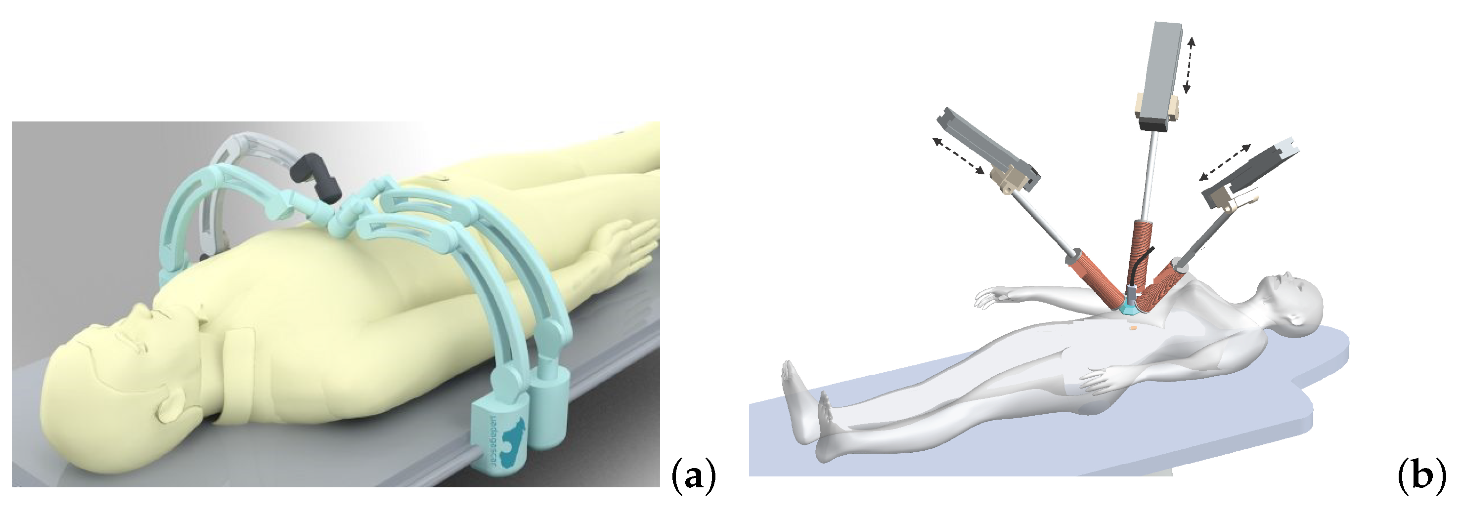
Magnetic microrobotics is a promising technology for improving minimally invasive surgery (MIS) with the ambition of enhancing patient care and comfort. The potential benefits include limited incisions, less hemorrhaging and postoperative pain, and faster recovery time. To achieve this, a key issue relies on the design of a proper electromagnetic actuation (EMA) setup which is based on the use of magnetic sources. The magnetic field and its gradient generated by the EMA platform is then used to induce magnetic torque and force for microrobot manipulations inside the human body. Like any control systems, the EMA system must be adapted to the given controlled microrobot and customized for the application.
1. Introduction

2. Theoretical Background
2.1. Magnetic Manipulation
EMA systems consisting of several electromagnets allow generating a magnetic field and/or a gradient field in a given workspace, as shown in Figure 2. These fields induce a magnetic torque and a force on the magnetized materials of the untethered microrobots. The expression of the magnetic field generated by an electromagnetic coil is derived from a single wire and the magnetic dipole. The magnetic field from any electromagnetic coil c can be approximated as a magnetic dipole characterized by its magnetic moment mc, and the point-dipole model is proposed. It can be shown that the magnetic field and its gradient are proportional to the electric current ic flowing through the coil c. The overall magnetic field generated by the n-coils is the superposition of each field. The magnetic field and its gradient are then expressed as:

where i=(i1,…,in)t is the electric current vector.
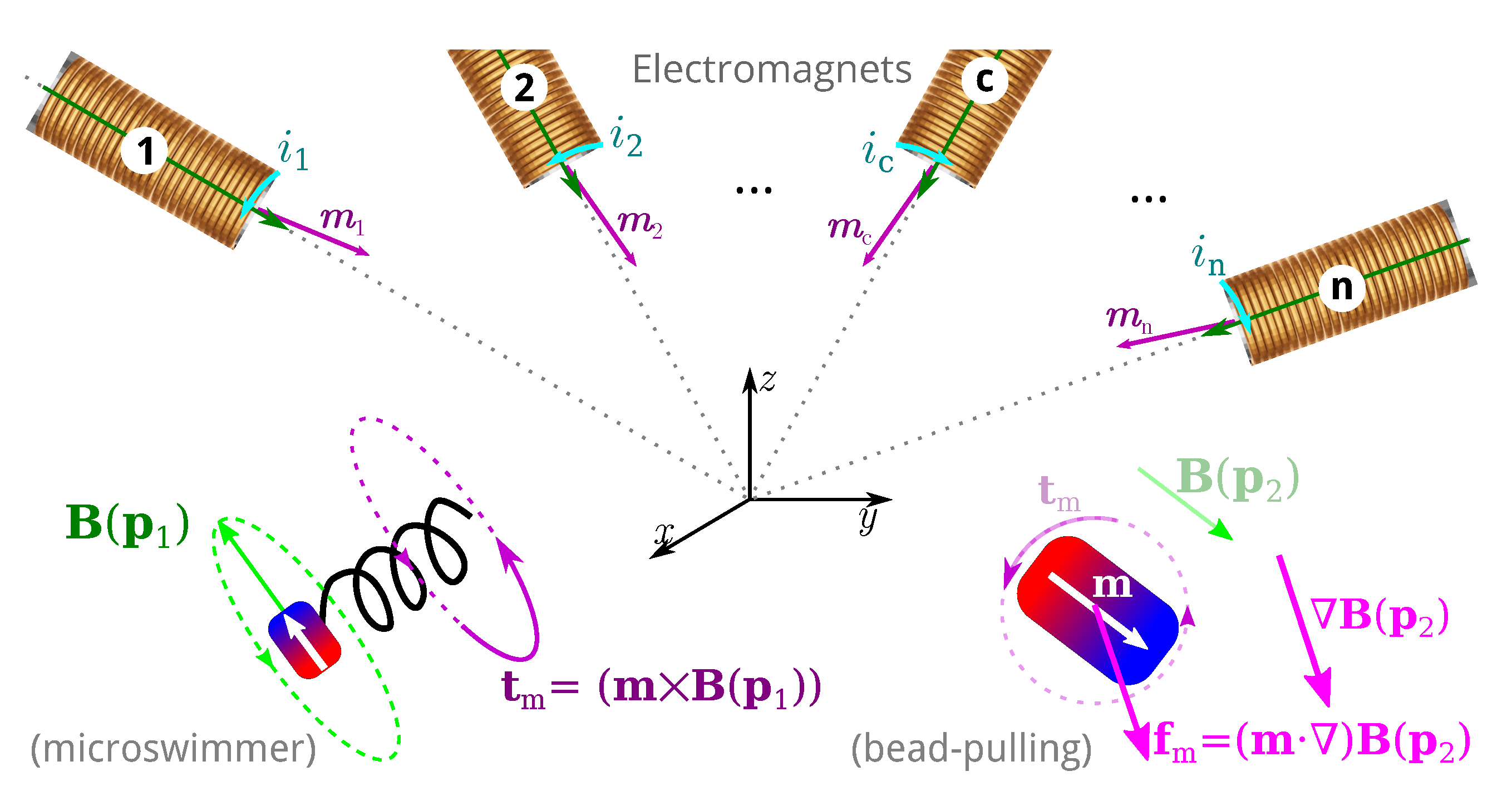

where A(m,p)∈R6×n is an actuation matrix mapping the current to the applied magnetic wrench. This magnetic actuation matrix is a function of both the position p∈Ω, and the magnetic moment m of the microrobot.
Therefore, substituting Equations (1) and (2) into Equation (3), the equations of torque and force can be presented by the actuation matrix A(m,p) in the further details as:
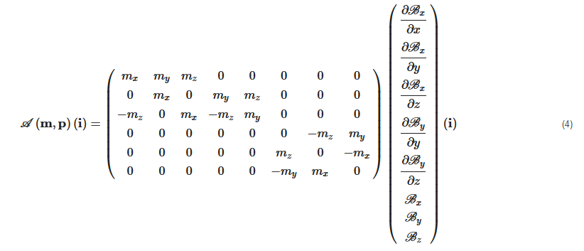
Each column of the matrix A(m,p) represents the wrench on the force and torque per unit current created by each electromagnet. If there are greater than n>6 electromagnets, the actuation matrix A(m,p) leads to a better conditioned matrix, a more isotropic workspace Ω, a reduction of singularity configurations, and lower current requirements [72][73][81]. In such cases, n>6, the EMA system is said "redundant" for the task. Especially, if A(m,p) has a full rank, for a desired force, f★m and torque, t★m, the actuation currents i can be calculated from the pseudo-inverse:
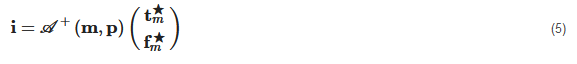
If n<6, the pseudo-inverse would be a least-squares approximation. Hence, for a controlled force and torque, the input current can be obtained only if the pseudo-inverse of A(m,p) exists. This derivation on the controlled current i can be similarly extended for controllers that require torque and/or force control [57].
2.2. Manipulation Analysis
From the mathematical analysis, the rank of force equation is 3 and the rank of torque equation is 2, the microrobot can maximally achieve three degrees-of-freedom (DOFs) in translation and two DOFs in rotation. Next, to achieve the five DOFs control of the microrobot, the minimum number of electromagnets is mathematical estimated. The three electromagnets can be used for three DOFs force control at a point, but normally five electromagnets are required when the orientation of the microrobot is dynamic changed. The number of electromagnets can be reduced to four, but either a nonmagnetic restoring torque or a nonmagnetic restoring force is required to stabilize the system. For two DOFs torque control, only three electromagnets are required because the three coils can generate a 3D field in a workspace. Thus, combined torque and force control requires a minimum of n=7 stationary electromagnets. Similarly, the seven electromagnets also need some additional external conditions. To stabilize the five DOFs control of the microrobot, the eight electromagnets are suggested for the fixed configuration system [83]. Reconfigurable EMA system can achieve similar control authority to stationary system with fewer electromagnets. Only n=5 electromagnets are required for torque and force control. Therefore, the mobile electromagnets are more particularly considered for the biomedical applications. Indeed, the field shape in the workspace can be modified by changing the location or orientation of the electromagnets during the magnetic actuation of the microrobot
[81].
2.3. Discussions

-
The dimensions of workspace;
-
The media of the environment;
-
The type of microrobots;
-
The medical tasks;
-
The required motion control.
Finally, the number of electromagnetic coils is determined by the specific motions of the selected microrobot. For instance, the translational locomotion can be achieved by the magnetic force on the spheroidal microrobot, and it can also be reached by the magnetic torque generated by rotating magnetic field on the helical microrobot.
3. The Electromagnetic Microrobotic Systems
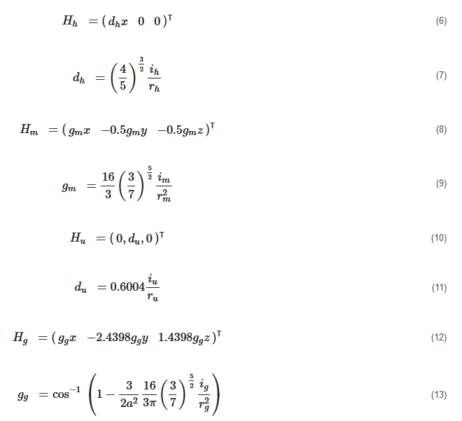
where ih and rh=r are the current and the radius of the Helmholtz coils; im and rm=r are the current and the radius of the Maxwell coils; iu and ru=r are the current and the radius of the uniform saddle coils; and ig and ru=g are the current and the radius of the gradient saddle coils.

As shown in Figure 6a, the Helmholtz set includes two solenoids with same radius rh separated by the distance: l=rh, and the Maxwell coil consists of a pair of same coils of radius rm separated with a distance l=3–√rm. The currents flowing in an Helmholtz coil pair have same intensity and phase, that is: ih=ihleft=ihright, while the currents of Maxwell coils are flowing in opposite phases, that is: imleft=−imright and im=|imleft|=|imright∣∣. It is clear that the magnetic fields generated by the combination of a Helmholtz coils pair and a Maxwell coils pair are different from that produced by two Helmholtz coils pairs. Hence, the different configurations of platforms composed of different coils pairs will be investigated. To make it easier to name each magnetic platform, the researchers introduce the abbreviation to identify them with the nomenclature provided in Table 1.
Table 1. ElectroMagnetic Actuation system nomenclature.
|
Symbol |
Description |
Symbol |
Description |
|---|---|---|---|
|
H |
Helmholtz coils |
M |
Maxwell coils |
|
U |
Uniform saddle coils |
G |
Gradient saddle coils |
|
E |
Electromagnet |
C |
single coil pair |
|
2D |
two-dimensions |
3D |
three-dimensions |
|
r |
rotational |
|
EMA |
Coils and Workspace |
Advantages |
Limitations |
|---|---|---|---|
|
HMr [49] |
4 coils, 2D |
Use few coils with simple structure; 2 DOFs of translation and 1 DOF of rotation; Manipulation of the orthotropic body. |
Low magnetic gradient over larger areas; Rotating coils limit medical applications. |
|
2C [70] |
4 coils, 2D |
Less number of coils, 18% smaller volume and 26.7% less power consumption to the same magnetic actuation. |
Non-uniform magnetic field at the edge of the workspace. |
|
2H2M [65] |
Eight coils, 2D |
Simple current control strategy; Uniform magnetic field and gradient; Manipulation of the orthotropic body. |
Low flexibility of the confined workspace. |
|
HMUG [62] |
Eight coils, 2D |
Common current control strategy; Compact setup with easy access; More efficient compared to the Maxwell and Helmholtz coils; Manipulation of the orthotropic body. |
Size of the proposed workspace is still limited; Non-uniform magnetic field at the edge of the workspace; Effective workspace is limited to the 2D plane. |
|
Ten coils, 2D |
Independent control of the multiple microrobots; Microparticles with different shapes. |
Only 2 DOFs motions (1 DOF rotational and 1 DOF translational) on a 2D plane; Confined workspace with difficult access; Important number of coils and power consumption. |
|
|
6E [92] |
Six coils, 2D |
Simultaneous independent positioning control of multiple microrobots; Simple structure and easy to implement; Heterogeneous sets of dissimilar magnetic microrobots have been tested. |
Complex control algorithms, and limited trajectory. |
|
3DMH [74] |
Six coils, 3D |
Compact and cheap setup; 3D manipulation of the orthotropic body. |
Limited workspace. |
|
2H2Mr [61] |
Eight coils, 3D |
Precise 3D motion; Fewer number of coils; Manipulation of the orthotropic body. |
Rotating coils limit medical applications; Large setup volume and power consumption. |
|
HMUGr [67] |
Eight coils, 3D |
Small setup volume and less consumption; Workspace accessibility; Almost all kind of microrobots. |
More powerful current suppliers are demanded that will cause overheating; The available workspace is still relatively small. |
|
H2US-MUG [63] |
Ten coils, 3D |
Compact structure; Precise magnetic field and gradient for 3D manipulation; Potential large range of applications. |
Large number of coils; Small and limited size. |
|
3DH [93] |
Six coils, 3D |
6 DOFs motion; Simple structure and easy to build; Control of the helical microswimmer. |
Complex algorithm and control strategy; Only the magnetic-field-based control. |
|
8E [94] |
Eight coils, 3D |
Compact structure; Arbitrary forces can be exerted on each microrobot independently and simultaneously. |
Small volume with few accessibility; Weak magnetic field and gradients. |
|
Good magnetic field; Hemispherical coils arrangement. |
Complex magnetic field description. |
||
|
9E [95] |
Nine coils, 3D |
Independent 3D control of pairs of microrobots; 6 DOFs motion; Workspace accessibility. |
Advanced control strategies are required; Large amount of energy consumption and heating. |
References
- Tendick, F.; Sastry, S.S.; Fearing, R.S.; Cohn, M. Applications of micromechatronics in minimally invasive surgery. IEEE/ASME Trans. Mechatron. 1998, 3, 34–42.
- Mack, M.J. Minimally invasive and robotic surgery. JAMA 2001, 285, 568–572.
- Carrozza, M.C.; Dario, P.; Jay, L.P.S. Micromechatronics in surgery. Trans. Inst. Meas. Control 2003, 25, 309–327.
- Purkayastha, S.; Athanasiou, T.; Casula, R.; Darzi, S.A. Robotic surgery: A review. Hosp. Med. 2004, 65, 153–159.
- Joseph, J.V.; Arya, M.; Patel, H.R. Robotic surgery: The coming of a new era in surgical innovation. Expert Rev. Anticancer Ther. 2005, 5, 7–9.
- Bogue, R. The development of medical microrobots: A review of progress. Ind. Robot. Int. J. 2008, 35, 294–299.
- Broeders, I.A.; Ruurda, J. Robotics revolutionizing surgery: The intuitive surgical “da Vinci” system. Ind. Robot. Int. J. 2001, 28, 387–392.
- Tsuda, S.; Oleynikov, D.; Gould, J.; Azagury, D.; Sandler, B.; Hutter, M.; Ross, S.; Haas, E.; Brody, F.; Satava, R. SAGES TAVAC safety and effectiveness analysis: Da Vinci® surgical system (Intuitive Surgical, Sunnyvale, CA). Surg. Endosc. 2015, 29, 2873–2884.
- Baek, S.J.; Kim, S.H. Robotics in general surgery: An evidence-based review. Asian J. Endosc. Surg. 2014, 7, 117–123.
- Grimsby, G.M.; Dwyer, M.E.; Jacobs, M.A.; Ost, M.C.; Schneck, F.X.; Cannon, G.M.; Gargollo, P.C. Multi-institutional review of outcomes of robot-assisted laparoscopic extravesical ureteral reimplantation. J. Urol. 2015, 193, 1791–1795.
- Morelli, L.; Guadagni, S.; Di Franco, G.; Palmeri, M.; Di Candio, G.; Mosca, F. Da Vinci single site© surgical platform in clinical practice: A systematic review. Int. J. Med Robot. Comput. Assist. Surg. 2016, 12, 724–734.
- Ferreira, A. (Ed.) The Encyclopedia of Medical Robotics; World Scientific: Singapore, 2018.
- Yang, G.Z.; Bellingham, J.; Dupont, P.E.; Fischer, P.; Floridi, L.; Full, R.; Jacobstein, N.; Kumar, V.; McNutt, M.; Merrifield, R.; et al. The grand challenges of Science Robotics. Sci. Robot. 2018, 3, eaar7650.
- Simaan, N.; Yasin, R.M.; Wang, L. Medical technologies and challenges of robot-assisted minimally invasive intervention and diagnostics. Annu. Rev. Control. Robot. Auton. Syst. 2018, 1, 465–490.
- Rattner, D.; Kalloo, A. ASGE/SAGES working group on natural orifice translumenal endoscopic surgery. Surg. Endosc. Other Interv. Tech. 2006, 20, 329–333.
- Romanelli, J.R.; Earle, D.B. Single-port laparoscopic surgery: An overview. Surg. Endosc. 2009, 23, 1419–1427.
- Tiwari, M.M.; Reynoso, J.F.; Lehman, A.C.; Tsang, A.W.; Farritor, S.M.; Oleynikov, D. In vivo miniature robots for natural orifice surgery: State of the art and future perspectives. World J. Gastrointest. Surg. 2010, 2, 217.
- Samarasekera, D.; Kaouk, J.H. Robotic single port surgery: Current status and future considerations. Indian J. Urol. IJU J. Urol. Soc. India 2014, 30, 326.
- Bae, S.U.; Jeong, W.K.; Baek, S.K. Current status of robotic single-port colonic surgery. Int. J. Med Robot. Comput. Assist. Surg. 2017, 13, e1735.
- Courreges, F.; Vieyres, P.; Poisson, G. Robotized tele-echography. In Teleradiology; Springer International Publishing: Berlin/Heidelberg, Germany, 2008; pp. 139–154.
- Sitti, M. Miniature devices: Voyage of the microrobots. Nature 2009, 458, 1121.
- Nelson, B.J.; Kaliakatsos, I.K.; Abbott, J.J. Microrobots for minimally invasive medicine. Annu. Rev. Biomed. Eng. 2010, 12, 55–85.
- Ceylan, H.; Giltinan, J.; Kozielski, K.; Sitti, M. Mobile microrobots for bioengineering applications. Lab Chip 2017, 17, 1705–1724.
- Honda, T.; Arai, K.; Ishiyama, K. Micro swimming mechanisms propelled by external magnetic fields. IEEE Trans. Magn. 1996, 32, 5085–5087.
- Abbott, J.J.; Peyer, K.E.; Lagomarsino, M.C.; Zhang, L.; Dong, L.; Kaliakatsos, I.K.; Nelson, B.J. How should microrobots swim? Int. J. Robot. Res. 2009, 28, 1434–1447.
- Alapan, Y.; Yasa, O.; Schauer, O.; Giltinan, J.; Tabak, A.F.; Sourjik, V.; Sitti, M. Soft erythrocyte-based bacterial microswimmers for cargo delivery. Sci. Robot. 2018, 3, eaar4423.
- Barbot, A.; Decanini, D.; Hwang, G. The Rotation of Microrobot Simplifies 3D Control Inside Microchannels. Sci. Rep. 2018, 8, 438.
- Carlsen, R.W.; Edwards, M.R.; Zhuang, J.; Pacoret, C.; Sitti, M. Magnetic steering control of multi-cellular bio-hybrid microswimmers. Lab Chip 2014, 14, 3850–3859.
- Carpi, F.; Kastelein, N.; Talcott, M.; Pappone, C. Magnetically controllable gastrointestinal steering of video capsules. IEEE Trans. Biomed. Eng. 2011, 58, 231–234.
- Diller, E.; Sitti, M. Micro-scale mobile robotics. Found. Trends® Robot. 2013, 2, 143–259.
- Ghosh, A.; Fischer, P. Controlled propulsion of artificial magnetic nanostructured propellers. Nano Lett. 2009, 9, 2243–2245.
- Hosney, A.; Abdalla, J.; Amin, I.S.; Hamdi, N.; Khalil, I.S. In vitro validation of clearing clogged vessels using microrobots. In Proceedings of the IEEE International Conference on Biomedical Robotics and Biomechatronics (BioRob), Singapore, 26–29 June 2016; pp. 272–277.
- Jeon, S.; Kim, S.; Ha, S.; Lee, S.; Kim, E.; Kim, S.Y.; Park, S.H.; Jeon, J.H.; Kim, S.W.; Moon, C.; et al. Magnetically actuated microrobots as a platform for stem cell transplantation. Sci. Robot. 2019, 4, eaav4317.
- Kim, S.; Qiu, F.; Kim, S.; Ghanbari, A.; Moon, C.; Zhang, L.; Nelson, B.J.; Choi, H. Fabrication and characterization of magnetic microrobots for three-dimensional cell culture and targeted transportation. Adv. Mater. 2013, 25, 5863–5868.
- Du Nguyen, V.; Le, V.H.; Zheng, S.; Han, J.; Park, J.O. Preparation of tumor targeting cell-based microrobots carrying NIR light sensitive therapeutics manipulated by electromagnetic actuating system and Chemotaxis. J. Micro-Bio Robot. 2018, 14, 69–77.
- Lee, S.; Lee, S.; Kim, S.; Yoon, C.H.; Park, H.J.; Kim, J.y.; Choi, H. Fabrication and characterization of a magnetic drilling actuator for navigation in a three-dimensional phantom vascular network. Sci. Rep. 2018, 8, 3691.
- Li, J.; de Ávila, B.E.F.; Gao, W.; Zhang, L.; Wang, J. Micro/nanorobots for biomedicine: Delivery, surgery, sensing, and detoxification. Sci. Robot. 2017, 2, 18–23.
- Li, J.; Li, X.; Luo, T.; Wang, R.; Liu, C.; Chen, S.; Li, D.; Yue, J.; Cheng, S.H.; Sun, D. Development of a magnetic microrobot for carrying and delivering targeted cells. Sci. Robot 2018, 3, eaat8829.
- Martel, S. Microrobotics in the vascular network: Present status and next challenges. J. Micro-Bio Robot. 2013, 8, 41–52.
- Mitchell, B.; Koo, J.; Iordachita, I.; Kazanzides, P.; Kapoor, A.; Handa, J.; Hager, G.; Taylor, R. Development and application of a new steady-hand manipulator for retinal surgery. In Proceedings of the IEEE International Conference on Robotics and Automation (ICRA), Roma, Italy, 10–14 April 2007; pp. 623–629.
- Palagi, S.; Fischer, P. Bioinspired microrobots. Nat. Rev. Mater. 2018, 3, 113–124.
- Park, S.; Cha, K.; Park, J. Development of biomedical microrobot for intravascular therapy. Int. J. Adv. Robot. Syst. 2010, 7, 91–98.
- Peyer, K.E.; Zhang, L.; Nelson, B.J. Bio-inspired magnetic swimming microrobots for biomedical applications. Nanoscale 2013, 5, 1259–1272.
- Qiu, F.; Nelson, B.J. Magnetic helical micro-and nanorobots: Toward their biomedical applications. Engineering 2015, 1, 21–26.
- Schürle, S.; Kratochvil, B.E.; Pané, S.; Zeeshan, M.A.; Nelson, B.J. Generating Magnetic Fields for Controlling Nanorobots in Medical Applications. In Nanorobotics; Springer International Publishing: Berlin/Heidelberg, Germany, 2013; pp. 275–299.
- Sitti, M.; Ceylan, H.; Hu, W.; Giltinan, J.; Turan, M.; Yim, S.; Diller, E.D. Biomedical Applications of Untethered Mobile Milli/Microrobots. Proc. IEEE 2015, 103, 205–224.
- Xie, H.; Sun, M.; Fan, X.; Lin, Z.; Chen, W.; Wang, L.; Dong, L.; He, Q. Reconfigurable magnetic microrobot swarm: Multimode transformation, locomotion, and manipulation. Sci. Robot. 2019, 4, eaav8006.
- Yesin, K.B.; Exner, P.; Vollmers, K.; Nelson, B.J. Design and control of in vivo magnetic microrobots. In Proceedings of the International Conference on Medical Image Computing and Computer-Assisted Intervention, Palm Springs, CA, USA, 26–29 October 2005; Springer International Publishing: Berlin/Heidelberg, Germany, 2005; pp. 819–826.
- Yesin, K.B.; Vollmers, K.; Nelson, B.J. Modeling and control of untethered biomicrorobots in a fluidic environment using electromagnetic fields. Int. J. Robot. Res. 2006, 25, 527–536.
- Steager, E.B.; Selman Sakar, M.; Magee, C.; Kennedy, M.; Cowley, A.; Kumar, V. Automated biomanipulation of single cells using magnetic microrobots. Int. J. Robot. Res. 2013, 32, 346–359.
- Fountain, T.W.; Kailat, P.V.; Abbott, J.J. Wireless control of magnetic helical microrobots using a rotating-permanent-magnet manipulator. In Proceedings of the IEEE International Conference on Robotics and Automation (ICRA), Anchorage, AK, USA, 3–7 May 2010; pp. 576–581.
- Torres, N.A.; Ruggeri, S.; Popa, D.O. Untethered microrobots actuated with focused permanent magnet field. In Proceedings of the ASME 2014 International Design Engineering Technical Conferences and Computers and Information in Engineering Conference, Buffalo, NY, USA, 17 August 2014; p. V004T09A024.
- Mahoney, A.W.; Abbott, J.J. Five-degree-of-freedom manipulation of an untethered magnetic device in fluid using a single permanent magnet with application in stomach capsule endoscopy. Int. J. Robot. Res. 2016, 35, 129–147.
- Lucarini, G.; Ciuti, G.; Mura, M.; Rizzo, R.; Menciassi, A. A new concept for magnetic capsule colonoscopy based on an electromagnetic system. Int. J. Adv. Robot. Syst. 2015, 12, 25.
- Ryan, P.; Diller, E. Magnetic actuation for full dexterity microrobotic control using rotating permanent magnets. IEEE Trans. Robot. 2017, 33, 1398–1409.
- Amokrane, W.; Belharet, K.; Souissi, M.; Grayeli, A.B.; Ferreira, A. Macro–micromanipulation platform for inner ear drug delivery. Robot. Auton. Syst. 2018, 107, 10–19.
- Schuerle, S.; Erni, S.; Flink, M.; Kratochvil, B.E.; Nelson, B.J. Three-dimensional magnetic manipulation of micro-and nanostructures for applications in life sciences. IEEE Trans. Magn. 2013, 49, 321–330.
- Martel, S.; Mathieu, J.B.; Felfoul, O.; Chanu, A.; Aboussouan, E.; Tamaz, S.; Pouponneau, P.; Yahia, L.; Beaudoin, G.; Soulez, G.; et al. Automatic navigation of an untethered device in the artery of a living animal using a conventional clinical magnetic resonance imaging system. Appl. Phys. Lett. 2007, 90, 114105.
- Kummer, M.P.; Abbott, J.J.; Kratochvil, B.E.; Borer, R.; Sengul, A.; Nelson, B.J. OctoMag: An electromagnetic system for 5-DOF wireless micromanipulation. IEEE Trans. Robot. 2010, 26, 1006–1017.
- Kratochvil, B.E.; Kummer, M.P.; Erni, S.; Borer, R.; Frutiger, D.R.; Schürle, S.; Nelson, B.J. MiniMag: A hemispherical electromagnetic system for 5-DOF wireless micromanipulation. In Experimental Robotics; Springer International Publishing: Berlin/Heidelberg, Germany, 2014; pp. 317–329.
- Jeong, S.; Choi, H.; Choi, J.; Yu, C.; Park, J.O.; Park, S. Novel electromagnetic actuation (EMA) method for 3-dimensional locomotion of intravascular microrobot. Sens. Actuators A Phys. 2010, 157, 118–125.
- Jeon, S.; Jang, G.; Choi, H.; Park, S. Magnetic navigation system with gradient and uniform saddle coils for the wireless manipulation of micro-robots in human blood vessels. IEEE Trans. Magn. 2010, 46, 1943–1946.
- Jeon, S.; Jang, G.; Choi, H.; Park, S.; Park, J. Magnetic navigation system for the precise helical and translational motions of a microrobot in human blood vessels. J. Appl. Phys. 2012, 111, 07E702.
- Choi, H.; Choi, J.; Jeong, S.; Yu, C.; Park, J.O.; Park, S. Two-dimensional locomotion of a microrobot with a novel stationary electromagnetic actuation system. Smart Mater. Struct. 2009, 18, 115017.
- Choi, H.; Choi, J.; Jang, G.; Park, J.O.; Park, S. Two-dimensional actuation of a microrobot with a stationary two-pair coil system. Smart Mater. Struct. 2009, 18, 055007.
- Choi, J.; Jeong, S.; Cha, K.; Qin, L.; Li, J.; Park, J.; Park, S. Positioning of microrobot in a pulsating flow using EMA system. In Proceedings of the IEEE RAS & EMBS International Conference on Biomedical Robotics and Biomechatronics, Tokyo, Japan, 26–29 September 2010; pp. 588–593.
- Choi, H.; Cha, K.; Choi, J.; Jeong, S.; Jeon, S.; Jang, G.; Park, J.O.; Park, S. EMA system with gradient and uniform saddle coils for 3D locomotion of microrobot. Sens. Actuators A Phys. 2010, 163, 410–417.
- Choi, H.; Cha, K.; Jeong, S.; Park, J.O.; Park, S. 3-D locomotive and drilling microrobot using novel stationary EMA system. IEEE/ASME Trans. Mechatron. 2012, 18, 1221–1225.
- Choi, H.; Park, J.O.; Park, S. Electromagnetic Actuated Micro- and Nanorobots; World Scientific: Singapore, 2018; Volume 2, Chapter 6; pp. 113–135.
- Go, G.; Choi, H.; Jeong, S.; Lee, C.; Park, B.J.; Ko, S.Y.; Park, J.O.; Park, S. Position-based magnetic field control for an electromagnetic actuated microrobot system. Sens. Actuators A Phys. 2014, 205, 215–223.
- Go, G.; Choi, H.; Jeong, S.; Lee, C.; Ko, S.Y.; Park, J.O.; Park, S. Electromagnetic navigation system using simple coil structure (4 coils) for 3-D locomotive microrobot. IEEE Trans. Magn. 2015, 51, 1–7.
- Diller, E.; Giltinan, J.; Jena, P.; Sitti, M. Three dimensional independent control of multiple magnetic microrobots. In Proceedings of the IEEE International Conference on Robotics and Automation (ICRA), Karlsruhe, Germany, 6–10 May 2013; pp. 2576–2581.
- Diller, E.; Giltinan, J.; Lum, G.Z.; Ye, Z.; Sitti, M. Six-degree-of-freedom magnetic actuation for wireless microrobotics. Int. J. Robot. Res. 2016, 35, 114–128.
- Dadkhah, M.; Kumar, N.; Yoon, J. Design and simulation of a 3D actuation system for magnetic nano-particles delivery system. In Proceedings of the International Conference on Intelligent Robotics and Applications, Busan, Korea, 25–28 September 2013; Springer International Publishing: Berlin/Heidelberg, Germany, 2013; pp. 177–187.
- Fu, Q.; Guo, S.; Huang, Q.; Hirata, H.; Ishihara, H. Development and evaluation of novel magnetic actuated microrobot with spiral motion using electromagnetic actuation system. J. Med Biol. Eng. 2016, 36, 506–514.
- Tehrani, M.D.; Kim, M.O.; Yoon, J. A novel electromagnetic actuation system for magnetic nanoparticle guidance in blood vessels. IEEE Trans. Magn. 2014, 50, 1–12.
- Yu, C.; Kim, J.; Choi, H.; Choi, J.; Jeong, S.; Cha, K.; Park, J.O.; Park, S. Novel electromagnetic actuation system for three-dimensional locomotion and drilling of intravascular microrobot. Sens. Actuators A Phys. 2010, 161, 297–304.
- Abbott, J.J.; Diller, E.; Petruska, A.J. Magnetic Methods in Robotics. Annu. Rev. Control. Robot. Auton. Syst. 2015, 3, 57–90.
- Charreyron, S.L.; Boehler, Q.; Kim, B.; Weibel, C.; Chautems, C.; Nelson, B.J. Modeling Electromagnetic Navigation Systems. IEEE Trans. Robot. 2021, 37, 1009–1021.
- Yu, R.; Charreyron, S.L.; Boehler, Q.; Weibel, C.; Chautems, C.; Poon, C.C.; Nelson, B.J. Modeling Electromagnetic Navigation Systems for Medical Applications using Random Forests and Artificial Neural Networks. In Proceedings of the 2020 IEEE International Conference on Robotics and Automation (ICRA), Virtual Conference, 1 June–31 August 2020; pp. 9251–9256.
- Chen, R.; Folio, D.; Ferreira, A. Mathematical approach for the design configuration of magnetic system with multiple electromagnets. Robot. Auton. Syst. 2021, 135, 103674.
- Miyashita, S.; Guitron, S.; Yoshida, K.; Li, S.; Damian, D.D.; Rus, D. Ingestible, controllable, and degradable origami robot for patching stomach wounds. In Proceedings of the IEEE International Conference on Robotics and Automation (ICRA), Stockholm, Sweden, 16–21 May 2016; pp. 909–916.
- Petruska, A.J.; Nelson, B.J. Minimum bounds on the number of electromagnets required for remote magnetic manipulation. IEEE Trans. Robot. 2015, 31, 714–722.
- Ko, Y.; Na, S.; Lee, Y.; Cha, K.; Ko, S.Y.; Park, J.; Park, S. A jellyfish-like swimming mini-robot actuated by an electromagnetic actuation system. Smart Mater. Struct. 2012, 21, 057001.
- Mathieu, J.B.; Martel, S.; Yahia, L.; Soulez, G.; Beaudoin, G. Preliminary studies for using magnetic resonance imaging systems as a mean of propulsion for microrobots in blood vessels and evaluation of ferromagnetic artefacts. In Proceedings of the Canadian Conference on Electrical and Computer Engineering. Toward a Caring and Humane Technology, Montreal, QC, Canada, 4–7 May 2003; Volume 2, pp. 835–838.
- Martel, S.; Mathieu, J.B.; Felfoul, O.; Macicior, H.; Beaudoin, G.; Soulez, G.; Yahia, L. Adapting MRI systems to propel and guide microdevices in the human blood circulatory system. In Proceedings of the Annual International Conference of the IEEE Engineering in Medicine and Biology Society, San Francisco, CA, USA, 1–5 September 2004; Volume 1, pp. 1044–1047.
- Bigot, A.; Tremblay, C.; Soulez, G.; Martel, S. Magnetic resonance navigation of a bead inside a three-bifurcation pmma phantom using an imaging gradient coil insert. IEEE Trans. Robot. 2014, 30, 719–727.
- Véron, B.; Hubert, A.; Abadie, J.; Andreff, N. Geometric analysis of the singularities of a magnetic manipulation system with several mobile coils. In Proceedings of the IEEE/RSJ International Conference on Intelligent Robots and Systems (IROS), Chicago, IL, USA, 14–18 September 2013; pp. 4996–5001.
- Yang, L.; Du, X.; Yu, E.; Jin, D.; Zhang, L. DeltaMag: An Electromagnetic Manipulation System with Parallel Mobile Coils. In Proceedings of the International Conference on Robotics and Automation (ICRA), Montreal, QC, Canada, 20–24 May 2019; pp. 9814–9820.
- Go, G.; Choi, H.; Lee, C.; Ko, S.Y.; Park, J.O.; Park, S. A multiple microrobot system with thermally responsive microclampers. In Proceedings of the IEEE International Conference on Biomedical Robotics and Biomechatronics (BioRob), Twente, The Netherlands, 24–26 August 2016; pp. 1186–1191.
- Go, G.; Choi, H.; Jeong, S.; Ko, S.Y.; Park, J.O.; Park, S. Selective microrobot control using a thermally responsive microclamper for microparticle manipulation. Smart Mater. Struct. 2016, 25, 035004.
- Diller, E.; Floyd, S.; Pawashe, C.; Sitti, M. Control of multiple heterogeneous magnetic microrobots in two dimensions on nonspecialized surfaces. IEEE Trans. Robot. 2011, 28, 172–182.
- Mahoney, A.W.; Sarrazin, J.C.; Bamberg, E.; Abbott, J.J. Velocity control with gravity compensation for magnetic helical microswimmers. Adv. Robot. 2011, 25, 1007–1028.
- Diller, E.; Giltinan, J.; Sitti, M. Independent control of multiple magnetic microrobots in three dimensions. Int. J. Robot. Res. 2013, 32, 614–631.
- Ongaro, F.; Pane, S.; Scheggi, S.; Misra, S. Design of an electromagnetic setup for independent three-dimensional control of pairs of identical and nonidentical microrobots. IEEE Trans. Robot. 2018, 35, 174–183.

