Electromagnetic Microrobotic Platforms for Biomedical Applications: Comparison
Please note this is a comparison between Version 1 by Antoine Ferreira and Version 3 by Peter Tang.

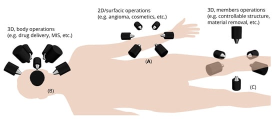
Magnetic microrobotics is a promising technology for improving minimally invasive surgery (MIS) with the ambition of enhancing patient care and comfort. The potential benefits include limited incisions, less hemorrhaging and postoperative pain, and faster recovery time. To achieve this, a key issue relies on the design of a proper electromagnetic actuation (EMA) setup which is based on the use of magnetic sources. The magnetic field and its gradient generated by the EMA platform is then used to induce magnetic torque and force for microrobot manipulations inside the human body. Like any control systems, the EMA system must be adapted to the given controlled microrobot and customized for the application. 

  • electromagnetic actuation
  • medical magnetic microrobots
  • minimally invasive surgery

1. Introduction

Magnetically actuated microrobots are of great interest for the development of innovative biomedical operations. The need to improve interventional operations has led to a wide range of minimally invasive procedures. Since most current operations are limited by the manual action of the surgeon, various robotic systems have been proposed to enhance minimally invasive surgery (MIS) [1][2][3][4][5][6][7][8][9][10][11][12][13][14][1,2,3,4,5,6,7,8,9,10,11,12,13,14]. Unlike the need of using rigid instruments with dexterous distal wrists, it is commonly more appropriate to use robotic tools that access internal tissues through small skin incisions [14][15][16][17][18][19][14,15,16,17,18,19]. Thanks to these medical robotic solutions the acceptance of their uses in clinical practice has been improved. For instance, researchers from the robotics field have developed solutions like robotized tele-echography to provide skilled medical care to isolated patients [20]. Meanwhile, various microrobotic systems have arisen to further reduce trauma, create new diagnosis tools and therapeutic procedures. For example, wireless microrobots with size of less than a millimeter are investigated to navigate within the body for targeted therapies [21][22][23][21,22,23].
Indeed, the design of miniaturized and versatile microrobotic systems potentially allows access to the entire human body, thus offering localized diagnoses and treatments with more precision and efficiency, but also to consider new procedures. For example, wireless microrobots, smaller than a millimeter, can navigate the body to perform targeted therapies [21][22][23][21,22,23]. A key issue lies in the actuation of such untethered microrobots within the human body. Among the various techniques developed so far, electromagnetic actuation (EMA) is considered to be the most promising one [13][21][22][23][24][25][26][27][28][29][30][31][32][33][34][35][36][37][38][39][40][41][42][43][44][45][46][47][48][49][50][13,21,22,23,24,25,26,27,28,29,30,31,32,33,34,35,36,37,38,39,40,41,42,43,44,45,46,47,48,49,50]. To this aim, many EMA platforms have been proposed to control untethered magnetic microrobots for biomedical applications [29][42][48][49][50][51][52][53][54][55][56][57][58][59][60][61][62][63][64][65][66][67][68][69][70][71][72][73][74][75][76][77][78][79][80][81][29,42,48,49,50,51,52,53,54,55,56,57,58,59,60,61,62,63,64,65,66,67,68,69,70,71,72,73,74,75,76,77,78,79,80,81]. Using EMA system circumvents the need of embedding power power sources into the microrobot [13][21][22][25][46][82][13,21,22,25,46,82].
To properly manipulate magnetic microrobots for the realization of reliable given biomedical applications, the EMA platform is one of the key elements. Consequently, the choice, the number and the placement of its magnetic sources are of prime importance [81]. Basically, magnetic sources can be produced by either permanent magnets [29][51][52][53][54][55][56][29,51,52,53,54,55,56] or electromagnets [42][48][49][57][58][59][60][61][62][63][64][65][66][67][68][69][70][71][72][73][74][75][76][77][78][42,48,49,57,58,59,60,61,62,63,64,65,66,67,68,69,70,71,72,73,74,75,76,77,78]. Nevertheless, most of the numerous EMA designs proposed by researchers do not follow any specific rule. It is not easy to choose the appropriate solution for a given application. At first, the electromagnetic sources of EMA systems could be organized either in a two-dimensional (2D) or in a three-dimensional (3D) arrangements, and apply properly to the different parts of the human body, as presented in Figure 1. As illustrated in Figure 1A, the 2D placement of magnets could be useful for surface operations such as angioma or cosmetic treatments. In the meanwhile, most MIS interventions require a 3D workspace, hence, the EMA system should be arranged in 3D above Figure 1B or around Figure 1C the workspace as well.
Figure 1.
The concept of EMA system applying for various biomedical applications.

2. Theoretical Background

2.1. Magnetic Manipulation

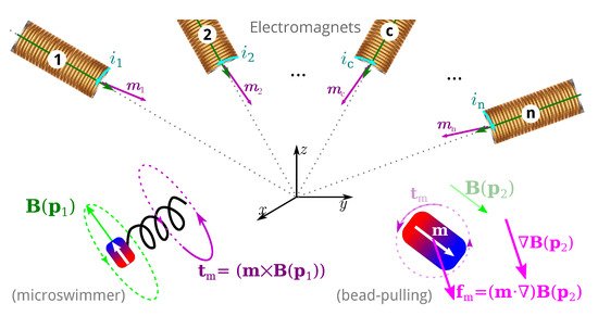
EMA systems consisting of several electromagnets allow generating a magnetic field and/or a gradient field in a given workspace, as shown in Figure 2. These fields induce a magnetic torque and a force on the magnetized materials of the untethered microrobots. The expression of the magnetic field generated by an electromagnetic coil is derived from a single wire and the magnetic dipole. The magnetic field from any electromagnetic coil c can be approximated as a magnetic dipole characterized by its magnetic moment mc, and the point-dipole model is proposed. It can be shown that the magnetic field and its gradient are proportional to the electric current ic flowing through the coil c. The overall magnetic field generated by the n-coils is the superposition of each field. The magnetic field and its gradient are then expressed as:

where i=(i1,…,in)t is the electric current vector.

Figure 2.
Illustration of the use of the magnetic manipulation of untethered microrobots.
When the magnetic dipole moment and the magnetic field are given, the induced magnetic torque and force can be easily obtained by the Maxwell’s equations. The induced magnetic field aligns the microrobot to a desired direction, and the magnetic force provides the propulsion force to move the microrobot to complete the task. Through the mathematical transformation, and for more convenient investigations of the magnetic actuation properties, the equations of torque and force can be rearranged into the following expression:

where A(m,p)∈R6×n is an actuation matrix mapping the current to the applied magnetic wrench. This magnetic actuation matrix is a function of both the position p∈Ω, and the magnetic moment m of the microrobot.

Therefore, substituting Equations (1) and (2) into Equation (3), the equations of torque and force can be presented by the actuation matrix A(m,p) in the further details as:

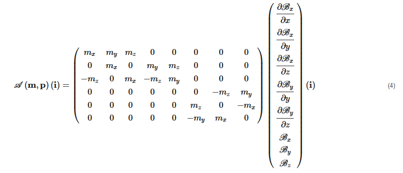
Each column of the matrix A(m,p) represents the wrench on the force and torque per unit current created by each electromagnet. If there are greater than n>6 electromagnets, the actuation matrix A(m,p) leads to a better conditioned matrix, a more isotropic workspace Ω, a reduction of singularity configurations, and lower current requirements [72][73][81][72,73,81]. In such cases, n>6, the EMA system is said "redundant" for the task. Especially, if A(m,p) has a full rank, for a desired force, fm and torque, tm, the actuation currents i can be calculated from the pseudo-inverse:

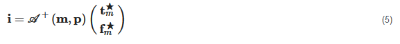
If n<6, the pseudo-inverse would be a least-squares approximation. Hence, for a controlled force and torque, the input current can be obtained only if the pseudo-inverse of A(m,p) exists. This derivation on the controlled current i can be similarly extended for controllers that require torque and/or force control [57].

2.2. Manipulation Analysis

From the mathematical analysis, the rank of force equation is 3 and the rank of torque equation is 2, the microrobot can maximally achieve three degrees-of-freedom (DOFs) in translation and two DOFs in rotation. Next, to achieve the five DOFs control of the microrobot, the minimum number of electromagnets is mathematical estimated. The three electromagnets can be used for three DOFs force control at a point, but normally five electromagnets are required when the orientation of the microrobot is dynamic changed. The number of electromagnets can be reduced to four, but either a nonmagnetic restoring torque or a nonmagnetic restoring force is required to stabilize the system. For two DOFs torque control, only three electromagnets are required because the three coils can generate a 3D field in a workspace. Thus, combined torque and force control requires a minimum of n=7 stationary electromagnets. Similarly, the seven electromagnets also need some additional external conditions. To stabilize the five DOFs control of the microrobot, the eight electromagnets are suggested for the fixed configuration system [83]. Reconfigurable EMA system can achieve similar control authority to stationary system with fewer electromagnets. Only n=5 electromagnets are required for torque and force control. Therefore, the mobile electromagnets are more particularly considered for the biomedical applications. Indeed, the field shape in the workspace can be modified by changing the location or orientation of the electromagnets during the magnetic actuation of the microrobot

[81].

2.3. Discussions

Various arrangements of electromagnetic coils can generate various magnetic field distributions. The EMA setup should be properly defined with respect to the envisioned biomedical application. To do so, the main characteristics should be specified, such as: the environment of the workspace, the type of microrobot and the various magnetic tasks. The required number of electromagnets for different motions control has been studied in past works [45][81][83][45,81,83]. On this basis, the relations between the specifications and the number of coils to design an EMA system can be proposed, and are depicted in Figure 3.
Figure 3.
The diagram of the specifications of EMA system design for (
a
) 2D and (
b
) 3D workspace.
Specifically, for the choice of a proper EMA system, five main characteristics of an application are required:
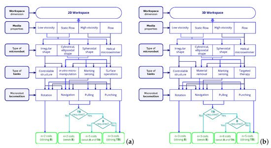
  • The dimensions of workspace;
  • The media of the environment;
  • The type of microrobots;
  • The medical tasks;
  • The required motion control.
First of all, the dimension of workspace is determined by the desired biomedical application that can be either 2D or 3D. The media of workspace could be divided into easy-to-operate and non-easy-to-operate for the placed microrobot. Commonly, the media with high viscosity or non-Newtonian fluid and the flowing status are difficult conditions to manipulate microrobot. In contrast, low viscosity and static environment are easy for the operation of microrobot. Moreover, the type of applied microrobot and its locomotion must be specified. Especially, the helical microrobot or microswimmer could be selected to move in a flowing environment and/or high viscosity media since these microrobots can perform drilling motion by the rotating magnetic field (see also Figure 2). Combining with magnetic force produced by magnetic gradient, the helical microrobot or microswimmer can be also actuated by a strong propulsion force. Besides, the cylindrical, ellipsoidal, spheroidal and irregularly shaped microrobot are chosen to the suitable environments. In addition, the type of locomotion of the microrobot should be determined with respect to the given application. As presented in Figure 3, six main types of biomedical applications are here considered. However, a distinction is made according to a 2D or 3D workspace that is considered. For a 2D workspace, as illustrated in Figure 3a, four main types of biomedical applications are considered for a 2D workspace: (i) surface treatment, (ii) marking/sensing, (iii) in vitro micromanipulation, and (iv) controllable structure. Whereas for a 3D biomedical operations, the main types of tasks are: (i) material removal, (ii) marking/sensing, (iii) targeted therapy, and (iv) controllable structure, as depicted in Figure 3b. For instance, almost all types of microrobot could be used for targeted drug delivery. However, the spheroidal microrobot rather than the helical microrobot is suitable for marking/sensing application. If a helical microrobot is applied for targeted drug delivery, the possible motion of microrobot is required as translation and rotation. If a spheroidal microrobot is used for targeted drug delivery, the possible motion could be translation, rotation and punching.

Finally, the number of electromagnetic coils is determined by the specific motions of the selected microrobot. For instance, the translational locomotion can be achieved by the magnetic force on the spheroidal microrobot, and it can also be reached by the magnetic torque generated by rotating magnetic field on the helical microrobot.

3. The Electromagnetic Microrobotic Systems

The magnetic microrobot can be efficiently actuated by the utilization of magnetic field and/or its gradient. This magnetic field could be generated from an EMA platform, that must obviously comprises some electromagnetic sources. The magnetic sources could be produced by either permanent magnets [29][51][52][53][54][55][56][29,51,52,53,54,55,56] or electromagnets [42][48][49][57][58][59][60][61][62][63][64][65][66][67][68][69][70][71][72][73][74][75][76][77][78][42,48,49,57,58,59,60,61,62,63,64,65,66,67,68,69,70,71,72,73,74,75,76,77,78], that should be selected according to the specified biomedical application. The main advantage of permanent magnet sources is that they do not require an external power supply, and they exhibit an advantageous volume to field-strength ratio [52]. However, in such case the magnetic fields can not be accurately adjusted or switched off [54]. In contrast, electromagnets can generate appropriate and flexible magnetic fields to effectively control the movement of microrobots. This study focuses on applications where magnetic fields and/or their gradients need to be continuously changed, and EMA setups using electromagnets are primarily considered in the following. The simplest electromagnet is wrapped around an air-filled core. In such case, the magnetic fields or their gradients can be uniformly defined in the workspace, and linear relationship can be expressed with their input currents. However, in such case, the strength of the magnetic field is weaker than using a permanent magnet on an equivalent volume. To increase the strength, a magnetic core with a high magnetic permeability can be added inside the coil to confine and guide the magnetic fields. The magnetic field is related to the electric current as well as to the properties of the magnetic core. Nevertheless, EMA system with several core-filled electromagnets may exhibit nonlinear and coupled behavior.
Furthermore, the EMA systems can also be distinguished into stationary and mobile. Stationary magnetic sources commonly use Helmholtz, Maxwell and saddle coils [61][62][63][64][65][67][69][71][74][84][61,62,63,64,65,67,69,71,74,84], as in MRI system [58][85][86][87][58,85,86,87], to induce magnetic fields and gradients that only are controlled by the current flowing into the electromagnetic coils. With such stationary configurations, the magnetic manipulation of the microrobot together with the workspace geometry remains limited by the stationary arrangement of coils. Conversely, moving magnets (e.g., actuated by a robotic system) can move around the target to enhance the manipulability of microrobots [88][89][88,89]. As the magnetic sources usually remain close to the microrobot, the moving coils also reduce the energy demand. In addition, they can change the local field distribution by adjusting the positions and/or orientations of the magnets [60][73][60,73].
As shown in Figure 4a, Fountain et al. [51] propose the use of nonuniform magnetic fields emanated from from a single rotating-permanent magnet manipulator for the control of magnetic helical microrobots, where the robotic arm brings the magnet closer to the patient, and the axial and radial controls cause the local magnetic field to change. Stereotaxis Inc. (Stereotaxis Inc., St. Louis, MO, USA, http://www.stereotaxis.com accessed on: 23 November 2021 has developed and commercialized the Niobe® robotic magnetic navigation system presented in Figure 4b. Niobe® uses two permanent magnets mounted on pivoting arms and positioned on opposing sides of the operating table to control proprietary catheters and guide-wires that have very small magnets at their distal tips. To circumvent the uncontrollability of the magnetic field generated by permanent magnets, Véron et al. [88] investigate a robot-assisted magnetic manipulation system with several mobile electromagnetic coils as represented in Figure 5b, where a robotic system keeps full dexterity for the use of electromagnetic coils while reducing energy consumption by a nearer manipulation. Furthermore, Yang et al. [89] demonstrate an electromagnetic manipulation system with three parallel mobile coils named DeltaMag and represented in Figure 5b. The proposed EMA system can remotely control the magnetic untethered devices in an enlarged workspace, moreover, the electromagnetic coils are actuated through the parallel mechanism to achieve the flexibility of their placement. Thus, the DeltaMag system proves that the mobile sources generated by moving electromagnets can improve the manipulability of localization to close the vicinity of the desired area and bring the good space utilization.
Figure 4. Examples of EMA systems with moving permanent magnets: (a) conceptual image of a rotating-permanent-magnet manipulator proposed by Fountain et al. [51], and (b) the Stereotaxis Niobe® consisting of two robotically-controlled magnets next to the table.
Figure 5. Examples of EMA systems with moving electromagnets: (a) the robot-assisted magnetic manipulation proposed by Véron et al. [88], and (b) the DeltaMag system consisting of three parallel mobile coils [89].
These electromagnetic microrobotic platforms can be divided into two-dimensional and three-dimensional manipulations. The status of electromagnetic coils could be stationary or mobile. The functions of designed electromagnetic platform vary according to the configuration of electromagnets. The Helmholtz coils pair, Maxwell coils pair, uniform saddle coils pair and gradient saddle coils pair are basic electromagnets configurations as shown in Figure 6 and are commonly used to generate a uniform magnetic field or gradient in a given workspace. The magnetic field intensity Hh, Hm, Hu and Hg of them can be computed as follows, respectively:

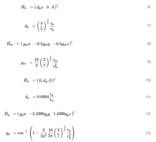
where ih and rh=r are the current and the radius of the Helmholtz coils; im and rm=r are the current and the radius of the Maxwell coils; iu and ru=r are the current and the radius of the uniform saddle coils; and ig and ru=g are the current and the radius of the gradient saddle coils.

Figure 6. Basic electromagnets configurations: (a) representation of an Helmholtz (inner red) and Maxwell (outer blue) coils pair.; and (b) representation of saddle-shaped coils: with same current iu flowing in the uniform saddle coil, and current ig in phase opposite for the gradient saddle coil.

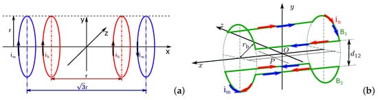
As shown in Figure 6a, the Helmholtz set includes two solenoids with same radius rh separated by the distance: l=rh, and the Maxwell coil consists of a pair of same coils of radius rm separated with a distance l=3–√rm. The currents flowing in an Helmholtz coil pair have same intensity and phase, that is: ih=ihleft=ihright, while the currents of Maxwell coils are flowing in opposite phases, that is: imleft=−imright and im=|imleft|=|imright∣∣. It is clear that the magnetic fields generated by the combination of a Helmholtz coils pair and a Maxwell coils pair are different from that produced by two Helmholtz coils pairs. Hence, the different configurations of platforms composed of different coils pairs will be investigated. To make it easier to name each magnetic platform, the researchers introduce the abbreviation to identify them with the nomenclature provided in Table 1.

Table 1. ElectroMagnetic Actuation system nomenclature.

Table 2 summarizes the comparison of the different EMA setups. More comparative and mathematical analyses regarding different configurations of EMA systems have been presented in the previous study [81].
Table 2. Comparisons of the EMA systems.

EMA

Coils and Workspace

Advantages

Limitations

HMr [49]

4 coils, 2D

Use few coils with simple structure; 2 DOFs of translation and 1 DOF of rotation; Manipulation of the orthotropic body.

Low magnetic gradient over larger areas; Rotating coils limit medical applications.

2C [70]

4 coils, 2D

Less number of coils, 18% smaller volume and 26.7% less power consumption to the same magnetic actuation.

Non-uniform magnetic field at the edge of the workspace.

2H2M [65]

Eight coils, 2D

Simple current control strategy; Uniform magnetic field and gradient; Manipulation of the orthotropic body.

Low flexibility of the confined workspace.

HMUG [62]

Eight coils, 2D

Common current control strategy; Compact setup with easy access; More efficient compared to the Maxwell and Helmholtz coils; Manipulation of the orthotropic body.

Size of the proposed workspace is still limited; Non-uniform magnetic field at the edge of the workspace; Effective workspace is limited to the 2D plane.

3H2M [90][91]

[90,91]

Ten coils, 2D

Independent control of the multiple microrobots; Microparticles with different shapes.

Only 2 DOFs motions (1 DOF rotational and 1 DOF translational) on a 2D plane; Confined workspace with difficult access; Important number of coils and power consumption.

6E [92]

Six coils, 2D

Simultaneous independent positioning control of multiple microrobots; Simple structure and easy to implement; Heterogeneous sets of dissimilar magnetic microrobots have been tested.

Complex control algorithms, and limited trajectory.

3DMH [74]

Six coils, 3D

Compact and cheap setup; 3D manipulation of the orthotropic body.

Limited workspace.

2H2Mr [61]

Eight coils, 3D

Precise 3D motion; Fewer number of coils; Manipulation of the orthotropic body.

Rotating coils limit medical applications; Large setup volume and power consumption.

HMUGr [67]

Eight coils, 3D

Small setup volume and less consumption; Workspace accessibility; Almost all kind of microrobots.

More powerful current suppliers are demanded that will cause overheating; The available workspace is still relatively small.

H2US-MUG [63]

Ten coils, 3D

Compact structure; Precise magnetic field and gradient for 3D manipulation; Potential large range of applications.

Large number of coils; Small and limited size.

3DH [93]

[94]

Six coils, 3D

6 DOFs motion; Simple structure and easy to build; Control of the helical microswimmer.

Complex algorithm and control strategy; Only the magnetic-field-based control.

8E [94]

[95]

Eight coils, 3D

Compact structure; Arbitrary forces can be exerted on each microrobot independently and simultaneously.

Small volume with few accessibility; Weak magnetic field and gradients.

[59][60]

[59,60]


Good magnetic field; Hemispherical coils arrangement.

Complex magnetic field description.

9E [95]

[96]

Nine coils, 3D

Independent 3D control of pairs of microrobots; 6 DOFs motion; Workspace accessibility.

Advanced control strategies are required; Large amount of energy consumption and heating.

Symbol

Description

Symbol

Description

H

Helmholtz coils

M

Maxwell coils

U

Uniform saddle coils

G

Gradient saddle coils

E

Electromagnet

C

single coil pair

2D

two-dimensions

3D

three-dimensions

r

rotational

   
ScholarVision Creations