Offshore wind turbines are becoming increasingly popular due to their higher wind energy harnessing capabilities and lower visual pollution. Structural integrity of offshore wind turbine and their blades’ aerodynamics are of particular importance, which can lead towards system-level optimal design and operation, leading to reduced maintenance costs.
1. Introduction
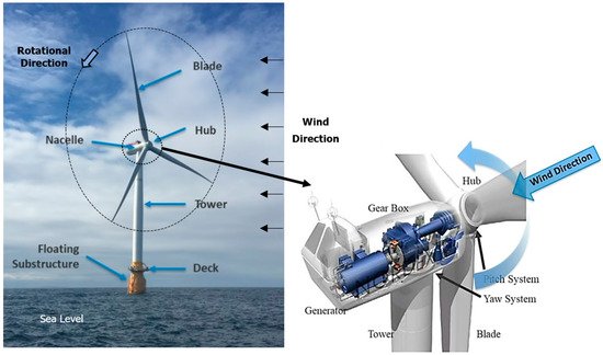
Offshore wind turbines offer significant benefits over onshore wind turbines. One of the key benefits offshore wind turbines offer is their comparatively bigger size, which translates into lower cost of power generation. Other benefits include lower environmental impacts, more wind energy resource available, etc. The main structure of offshore wind turbines is not very different from onshore wind turbines, as shown in Figure 1. Most commercial offshore wind turbines are horizontal-axis 3-bladed upwind machines, where the above-sea-level components include torque generating blades connected to the hub, which is an integral part of the nacelle. Housed in the nacelle is the main shaft, the gearbox (if applicable) and the generator. Power cables run down from the nacelle through the tower to the supporting structure, which has an outer deck for the operators to gain access to the tower and up to the nacelle. It is noteworthy that for offshore wind harnessing, horizontal axis wind turbines are preferred over vertical axis wind turbines due to their higher wind harnessing capability (bigger commercially affordable size).
Figure 1. A typical offshore wind turbine (Adapted with permission from ref.
[1]. Copyright 2020 Webinar Hosted by National Renewable Energy Laboratory).
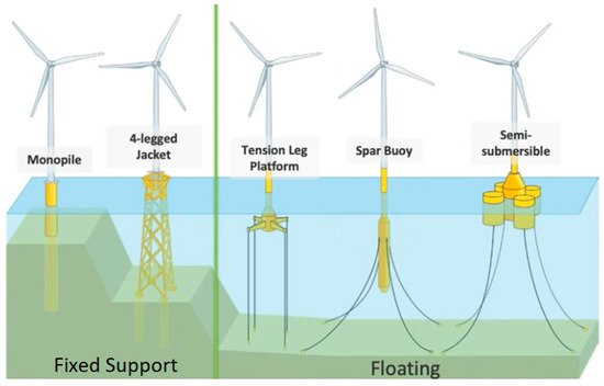
The main difference between onshore and offshore wind turbines is how offshore wind turbines are structurally supported. There are broadly two types of offshore wind turbines, i.e., fixed-support and floating. Further classification of offshore wind turbines is shown in
Figure 2. It can be seen that there are two types of fixed-support offshore turbines in operation commercially, i.e., monopile and jacket. A monopile support consists of a single tower-like structure embedded into the seabed through suction and gravity, whereas jacket support structure comprises of three or four-legged lattice configurations. The primary constraint that fixed-support offshore wind turbines face is that they can be installed in a maximum seabed depth of 60 m. In deep waters (>60 m depth), fixed-support structures become commercially inviable, i.e., cost of installation increases considerably. Most of the commercially installed and operational offshore wind turbines in the world (currently) have fixed-support structures
[2]. However, there are some significant issues with this technology. The foremost issue is that more than 80% of offshore wind energy is available off-coast, i.e., far away from land and in deep waters (seabed depth of >60 m). Another limiting factor of fixed-support wind turbines is their size; the biggest rotor diameter currently installed is 80 m, with the turbine having rated power of 1.8 MW. The visual impact of these type of offshore wind turbines is another factor to be considered seriously.
Figure 2. Support structures for offshore wind turbines (Adapted with permission from ref.
[1]. Copyright 2020 Webinar Hosted by National Renewable Energy Laboratory).
The three different types of support structures for floating offshore wind turbines are shown in Figure 2. The first one depicted is tension leg support in which three or four mooring cables are connected from the floating substructure to the seabed. The mooring cables are in tension and thus, provide static support to the wind turbine. The limiting factor for this technology is the size of the substructure; if it is too big, the tension in the cables need to be significantly higher and thus, the cost of installation increases. The second type of floating wind turbine’s support structure is spar buoy, where a tower-like substructure (sometimes also called as transition piece), filled with ballast, is connected to the seabed through mooring cables. The structural stability under severe weather conditions is an area of ongoing research for these turbines, along with the configuration of the mooring cables. It is noteworthy here that mooring cables are roughly 4 times in length than the seabed depth, thus having considerable costs. The third type of support structure for floating offshore wind turbines is known as semi-submersible, which has many different configurations (only one type shown in Figure 2). The basic idea is to attach buoyant structures with the main substructure (or transition piece). The static structure is achieved through varying the buoyancy in these semi-submersible structures. The floating substructure is connected to the seabed via mooring cables. An important point to note here is that when a floating structure is termed as static, it doesn’t mean that it is absolutely stationary.
There are currently many technological developments regarding offshore wind turbines aimed at reducing the costs involved with the installation of offshore wind farms. These include increasing array voltage to 66 kV for lower costs. It is noteworthy here that electrical array cable cost increases with wind turbine spacing and decreases with their size. However, there is a trade-off in wind turbine spacing between array cable cost and wake losses from the wind turbines. Generally, a spacing of 6D to 8D is considered between consecutive offshore wind turbines, where D is the rotor diameter. The installation cost of offshore wind farms, however, is constantly decreasing due to various factors, such as technological improvements. Cost modelling shows a 70% decrease in the cost of power (per unit) from 2015 to 2025 from fixed-support offshore wind turbines, with floating turbines converging on similar cost of per unit kWh by 2030
[3].
The operation and maintenance of offshore wind turbines involve significant costs. According to Rockmann
[4], 25–30% of the total life cycle cost of offshore wind turbines are associated with operation and maintenance. Expanding on offshore wind turbine maintenance, there are two main types, i.e., small and major. Small repairs can be carried out in the field using vessels and remotely operated vehicles (ROVs). This includes repairing and replacing sensors, lubrication, preventive maintenance, etc. For major repairs, offshore wind turbines are normally disconnected from the mooring cables and towing them to onshore facilities. Major repairs include repair of damaged blades, gearboxes, generators, etc. Moreover, recent developments in offshore wind turbine technology are contributing significantly towards lowering the lifecycle costs of offshore wind turbine projects.
2. Flow Characterization of Offshore Wind Turbines
The complex interactions of blades with the surrounding wind dictates the aerodynamic performance of wind turbines. Thus, it is essential to examine and understand the underlying physical mechanisms associated with their operations. Usually, either experimental or computational methods are adopted to perform such investigations. The later scheme of work can be broadly classified into computational simulations through directly solving incompressible Navier–Stokes (NS) equations. In these approaches, appropriate turbulence modeling strategies or low-order aerodynamic models are incorporated into the computations relying on classic aerodynamic potential flow-based theories and wake models.
The advantage of using experimental techniques is their ability to replicate more realistic conditions for offshore wind turbines. However, maintaining controlled environments to carry out meaningful investigations is a challenging task. Because wind turbines operate with their foundations installed over moving platforms encountering intense wave loads from oceanic water, it changes kinematic conditions of blades having interactions with the on-coming wind. These phenomena add more complexity to the mechanics of such dynamic systems. Important considerations emerge with respect to the aerodynamic performance of wind turbines when they operate in the form of clusters (wind turbine farms). Wave tanks have proven to be effective in quantifying fluidic loads on submersible platforms for different depths.
Investigating the wake dynamics and its correspondence with the aerodynamic performance of offshore wind turbines involves numerous challenges. These include handling multi-component flows with both air and water, requiring large mesh sizes to capture velocity gradients near blades and near wakes, modeling accurate wave loads on the base of turbines and incorporating atmospheric turbulence for inflows of wind. There are different computational methods for handling movements of a turbine and its base, while dealing with kinematics of turbines with moving platforms. Commonly employed techniques in computational fluid dynamics (CFD) include dynamic meshing
[5], overset or Chimera grids
[6][7][8][9][10] and sliding mesh technique or arbitrary mesh interfaces (AMI)
[11]. Each of these methods has its own strengths and specific limitations. For example, dynamic meshing technique suffers from low-order accuracy and numerical instability due to the generation of mesh elements with poor quality or high skewness. On the contrary, the other two techniques provide more flexibility in terms of maintaining the quality of cells and interpolating flow quantities in different grids. However, preparing appropriate meshes for these computational techniques require skills and expertise.
Full-order CFD simulations can be computationally expensive. It is a common practice in designing wind turbines to rely on low-order modeling techniques based on potential flow models
[12] or blade element momentum (BEM) theory
[13]. Traditionally, computationally cost-effective simulation frameworks are used, including FLEX, FAST or GH Bladed, which rely on simplistic models, particularly modelling inline forces on bodies interacting with oscillatory flows
[14] that remains valid for cylindrical structures with smaller diameters
[15]. Despite their low computational cost, they do not handle viscous effects
[12], which are important to determine hydrodynamic and aerodynamic features associated with floating foundations, rotating blades, nacelle and tower. Moreover, their capability to model large-amplitude motions and their related phenomena is limited and it involves large deviations from experimental measurements.
Offshore structures usually experience extreme weather conditions, which involve stormy winds and strong waves interacting with the atmospheric boundary layer. To establish the reliability of offshore wind turbines for continuous power generation, it is imperative to understand the impact of turbulent flow conditions on their aerodynamic performance and underlying fluid–structure–acoustic interaction. Traditionally, computational modeling of turbulent flows for these systems involves using various Reynolds-Averaged Navier-Stoke (RANS) equations-based models
[5][6][7][11][16][17][18][19][20], large eddy simulations (LES)
[21][22], and different versions of detached eddy simulations (DES)
[8][9][10][23]. Other low-order wake models
[24] are also introduced along with potential flow-based methods to handle unsteady flow dynamics. Recently, a few studies
[22][24][25][26][27] have been carried out to incorporate the modeling of turbulent wind fields over oceans and irregular wave loads on the floating submersible structures
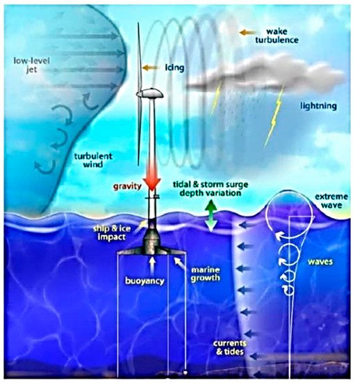
[15]. Primary differences in physical phenomena associated with offshore wind turbines and their urban counterparts include hydrodynamic excitations of foundational platforms. It is due to wave loads and turbulence in the atmospheric boundary layer over oceans, which are graphically shown in
Figure 3.
Figure 3. Types of wind and wave loadings on an FOWT
[28].
2.1. Excitation of Foundation Platforms
Understanding the effects of wave loading on floating foundations of offshore wind turbines is important as it has large implications on angles-of-attack formed by rotating blades with the on-coming wind. This affects the formation and shedding of coherent flow structures, which determine the aerodynamic performance of turbines and their power generating capacity. The six degrees-of-freedoms (DOFs) associated with a floating offshore wind turbine include three translational DOFs representing heave (vertical), surge (along the central axis of the rotor) and sway motions. The three rotational DOFs are yaw (around the central axis of the tower), roll (around the central axis of the rotor) and pitch motions. Wave loads or hydrodynamic excitation on floating structures can represent regular as well as irregular sea states. These interactions of waves can cause surge, pitch, yaw or roll motion for the base platforms. Both vertical-axis wind turbines (VAWTs) and horizontal-axis wind turbines (HAWTs) are designed with floating platforms. VAWTs require simpler blade geometries and have better stability with floating platforms, which mitigates the development of fatigue loads in blades
[8][9].
A usual phenomenon in wind turbine aerodynamics is the experience of yawed flows by turbines, where the wind encounters the blades making an angle with the rotor axis. Wen et al.
[29] performed numerical simulations to determine the effects of static and dynamic yaw motion on the angles-of-attack (α) of blades by using free-vortex method, based on potential flow theory. It was determined that variations in α were associated with three different phenomena: the blade advancing and retreating effect, the non-uniform induction effect and the upwind and downwind yawing effect. Different mathematical terms in the definition of α are used under different flow and kinematic conditions to attribute changes in α with these three phenomena. The first one explains a situation, where a blade is first advancing, and then, retreating from the vortex wake. The second one belongs to the quantification of axial induction factor, which shows reduction in wind velocity from free-stream value near the rotor. The last phenomenon relates to the yawing motion of the platform to align the rotor with the in-coming wind. Bounds on positive and negative α have also been explained due to these phenomena under static and dynamic yawing conditions. The surge motion has the potential to significantly affect the wake of a FOWT by stretching and compressing three-dimensional vortex structures. Having different length scales, vortices are shed from the rotating blades and other components, such as nacelle and tower. The moving offshore platform can lead rotors to move forward and backward, causing propeller-like conditions or vortex-ring states
[6]. Lei et al.
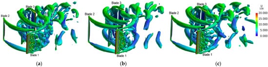
[8] used a CFD solver STAR-CCM+ with the improved delayed detached eddy simulation (IDDES) using overset meshing technique for a 3-bladed vertical-axis wind turbine with its foundation undergoing a periodic surge motion. They determined that variations in surging amplitudes caused maximum torque appearing in different intervals of a period, which has a direct influence on fatigue loads over blades. This surge motion of the foundation can significantly affect the aerodynamics of turbines. Smaller amplitudes with smaller surging frequencies not only mitigates oscillations in aerodynamic forces and unbalancing moments, but it also helps keep turbines steady with higher power output. Their flow visualizations shown in
Figure 4 depict that stronger large-sized flow structures are formed when a FOWT experiences surge motion of its base.
Figure 4. Coherent structures around an offshore vertical-axis wind turbine at (
a) mean surge position, (
b) maximum surge displacement and (
c) no surge motion (Adapted with permission from ref.
[8]. Copyright 2017 Energy).
Stand-alone pitching motion has substantial impact on the aerodynamic forces and moments experienced by floating wind turbines. Their performance parameters are sensitive to variations in pitching amplitude and frequency
[9]. Lei et al.
[9] used STAR-CCM+ with the improved delayed detached eddy simulation (IDDES) using overset mesh technique for a 2-bladed offshore floating vertical-axis wind turbine with its base undergoing pitching motion. The periods of pitching motion are considered as integral multiples of the blades’ rotational periods. It has been observed that the turbine experiences more torque at maximum pitching amplitudes compared to that at no pitching states. Blade tip vortices are more coherent for pitching conditions than those with no pitching motion. However, an oscillating base also causes more intense interactions between blade-tip vortices. The induced velocity due to the pitching platform affects the relative speed between blades and in-coming wind. It consequently influences the aerodynamic parameters. In this scenario, another key factor is increasing sweep area of the turbine rotor. Another study by Lei et al.
[10] reveals that some pitching motion profiles can cause expansion of momentum-deficit regions in the wake. However, a clearer trend for its dependence on pitching amplitudes and frequencies cannot be determined properly. Wen et al.
[30] introduced two other governing parameters, tip speed ratio (TSR; λ) and reduced frequency (ω), in their investigations, which have been defined as:


where Ω is the angular velocity of rotor, R is its radius, U
∞ is the in-coming wind velocity, β
o is the maximum pitch angle, H is the tower height and k represents a correlation between oscillation frequency and amplitude. The latter parameter also has certain significance in offshore environments, as turbulent sea states involve large β
o and lower ω
[31]. They found that the time-averaged power (
) has a direct relationship with k. For lower λ,
decreases with an increasing k, whereas
decreases under such conditions for higher λ. Higher fluctuations, which are detrimental for the structural integrity of a wind turbine, were computed for increase in both these parameters.
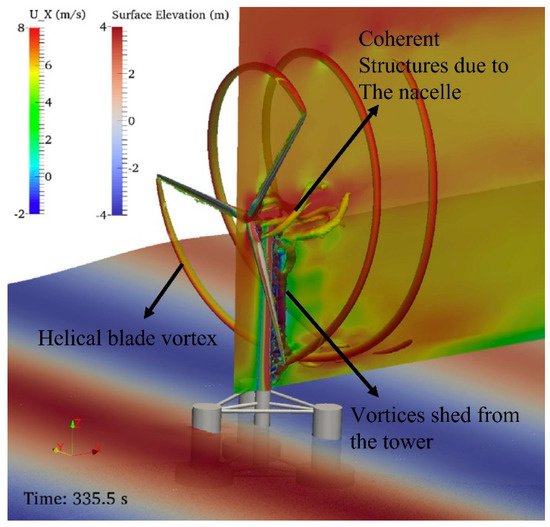
Fully coupled computational solvers integrating wind, wave and structural dynamics propose the most accurate numerical tools for investigating FOWTs. There are a few studies in recent literature where excitations in multi-DOFs for foundations of FOWTs have been considered
[15][11][32][20][33][34][35][36][37]. Volume-of-fluid (VoF) method has been utilized to capture the air–water interface and the formation of free surfaces. The following models have been introduced in the solver to define wave conditions at the inlet boundary:


In these models, A and θ denote amplitude and phase of the wave, respectively. Moreover, θ = kx − ωt with k and ω being the wave number and circular wave frequency, respectively. Additionally, H = 2A stands for the wave height and d is the depth of water. An important concern in computational modeling of these problems involves handling the reflection of waves from the outlet boundary. This was achieved by introducing a sponge layer near the outlet boundary by adding a source term in the Navier–Stokes equation for momentum balance. This source term contains an artificial viscosity term as a damper in the virtual environment. Figure 5 depicts the coherent flow structures formed due to rotating blades, tower, and the nacelle of the turbine.
Figure 5. Coherent structures around a floating offshore wind turbine
[11].
2.2. Numerical Modeling for Control Design
Controlling wind turbines in offshore farms is used to improve their aerodynamic performance, power generation and coordination with other turbines in the farm. Control techniques are devised to make interactions of turbines and their wakes more productive. Quite interestingly, wakes of wind turbines are deflected
[38] and those present in the downstream direction should not directly interact with the momentum-deficit regions in the wakes of upstream turbines. For this purpose, yaw-based wake steering technique is employed to enhance the net power generation of turbines placed in arrays
[39]. Fleming et al.
[40] developed a wind farm controller to carry out wake steering and implemented it over a commercial offshore wind farm in China by partnering with Envision turbines, a company for manufacturing turbines. Owing to their simpler formulations and low computational cost, low-order aerodynamic/hydrodynamic models are vastly used in designing controllers for large structures.
2.3. Offshore Wind Turbine Farms
Installing wind turbines in the form of clusters and farms can significantly increase their performance; downstream turbines can extract energy from the vortical flows shed by their upstream counterparts
[41][42]. Additionally, direct interactions of velocity-deficit regions in the wake of an upstream turbine with the rotating blades of a downstream one degrades its performance
[3]. Hence, it demands special care of setting the spaces between floating offshore wind turbines when they are arranged in arrays
[43]. Due to the allied cost and complexity for replicating wind and wave conditions in controlled laboratory environments, computational techniques are favored for studying these effects and their consequences. Though virtual in nature, they provide considerable flexibility to introduce variations in the governing parameters and changing array configurations of turbines. Hence, the most recent advancements in this field rely on numerical simulations to determine the aerodynamic performance of offshore wind farms. However, the associated computational cost is enormous due to the multi-physical nature of these systems and mesh requirements to solve governing mathematical models.
2.4. Flow Induced Acoustics
When solid structures undergo motion in a fluid, pressure waves are generated in their surroundings, propagating acoustic signals. These features can cause noise pollution in aquatic environments and disturb the natural habitats of marine species. Due to the construction of large farms of floating offshore wind turbines in oceans, migration routes of aquatic animals can be changed, which would have an adverse impact on underwater ecosystems. It is therefore important to quantify flow-induced sound emitted due to operations of these floating structures. Offshore wind turbines also reduce the sensitivity of seismic stations to measure the low-frequency motion signals in ocean beds due to earthquakes or testing of mass-scale weapons. Moreover, mixed seismic signals are produced by the support structures and mooring cables. Thus, it is important to examine the emitted flow-induced aero-acoustic signals.
Thus, more extensive efforts are required to understand how flow-induced acoustic signals from offshore wind turbines impact the lives of biological species. Evaluating the impact of governing kinematic parameters of wave loading, turbulence intensity and tip–speed ratio is required to come up with more effective designs of offshore wind turbines. Simultaneously, detailed knowledge on fluid–structure–acoustic interactions should be obtained, so that effective flow control strategies can be designed and implemented. A significant gap in our current knowledge relates to the emission and propagation of acoustic signals when multiple offshore wind turbines operate in close proximity of one another.
3. Structural Integrity of Offshore Wind Turbines
3.1. Wind Turbine Blades
Boudounit et al.
[44] have carried out numerical investigations on the structural integrity of wind turbine blades under in-service and off-service wind conditions. Finite element models of two different wind turbine blades, one made of fiberglass/epoxy composite and the other made of carbon fiber/epoxy composite, have been created as shell elements in the numerical environment. The length of both blades was 48 m, weighing 12.18 t for fiberglass/epoxy and 9.54 t for carbon fiber/epoxy. The aerodynamic design of the blades considered was NACA4424 with a maximum camber of 4–14% from the leading edge and a maximum thickness of 24%. Encastre type constraints have been applied at the blade root, while all three aerodynamic gravity and centrifugal wind loads have been incorporated into the model (in-service at 25 m/s and off-service at 75 m/s). Hashin’s criteria for damage initiation in composite materials (firer and matrix failure modes, i.e., fiber tension/compression and matrix tension/compression) have been used to analyze the structural integrity of the blades
[45][46]. The numerically predicted results indicate that the blade tip displacement in case of fiberglass/epoxy composite blades is significantly higher than carbon fiber/epoxy blades; under off-service conditions, it can be 2.2 times more. Hashin’s criteria has been met by the fiberglass/epoxy composite blade at 55 m/s wind speed, leading to matrix cracking followed by fiber-matrix interface violation and eventually fiber failure. The stiffness of carbon fiber/epoxy blades has been recorded to be 3.7 times higher than fiberglass/epoxy blades, making them a more suitable material for wind turbine blades manufacture. Hand et al.
[47] carried out extensive finite element analysis (FEA) on a 5 MW offshore wind turbine blades made of glass fiber reinforced polymer. Structural analyses have been carried out at most critical wind load cases as defined in IEC 61400-01 Class 1A
[48], for example at 70 m/s. Longitudinal strain has been analyzed along the spanwise direction of the blades. The numerical results obtained show compressive strain on the camber face of the blade, at the blade mid-span, with values of the longitudinal strain well within the allowable limits. This has been compared against the results from an analytical model, which assumes the blade as a beam with all the parts lumped together. It has been computed that the analytically calculated longitudinal strain on a blade is 8.7% higher. The maximum flapwise deflection at the blade mid-span has been numerically predicted to be 2.9 m under critical wind load conditions. The study also states some recommendations for future work, which include analysis of blade fatigue resulting from varying azimuthal angle (and hence, varying aerodynamic loads), fluid-structure interaction-based studies, etc.
3.2. Offshore Wind Turbine Substructure
The main difference between onshore and offshore wind turbines is the way they are supported and thus, substructures are an integral part of offshore turbines. A significant number of recent scientific investigations have been carried out on fixed support type offshore wind turbines, while very few studies are publicly available on floating offshore wind turbines. It is, however, noteworthy that the future of offshore wind turbine technology lies with the floating offshore wind turbines as their rated power can be significantly higher than fixed support offshore turbines, potentially making them more cost per kWh effective.
Oh and Ishihara
[49] carried out a full-scale structural analysis of a 2.4 MW offshore wind turbine with a gravity support structure. The empirical investigations have been carried out through excitation testing of an active mass damper, analyzing the damping ratios for different frequency modes. Sinusoidal vibration and free decay testing criteria have been employed for estimating the structural mechanics of the wind turbine. Results show that the damping ratios during sinusoidal vibration testing are 0.2% for the first mode and 2.4% for the second mode. For free decay testing, the fore-aft modes are similar to the sinusoidal vibration testing. However, side-side modes result in damping ratios of 1.2% and 3.2%, respectively, for the first and second modes. An empirical model has been developed to estimate the damping ratio for the first mode. This work has been expanded further by Ishihara and Wang
[50] to induce the effects of soil properties using genetic algorithm (GA). Numerical investigations have been carried out on gravity support and monopile support structures, and the modal results validated against field data. It has been observed that the damping ratio is strongly dependent on the soil stiffness. The increase in damping ratio for the second mode of gravity support structure is due to the riprap layer, which is softer than the original soil. For the monopile support structure, soil stiffness affects both modes. Gentils et al.
[51] have carried out numerical investigations on the structural mechanics and optimal design of offshore wind turbine support structures. Finite element analysis (FEA) has been coupled with GA (integrated optimization) with the objective of minimizing the weight of the monopile support. The optimization criteria employed are the standard requirements of vibrations, stress, deformation, buckling, fatigue and design constraints. The integrated optimization model has been applied to 5 MW turbine from the National Renewable Energy Laboratory
[52]. Numerical predictions for the aero-hydro-elastic analyses have been validated against the reference offshore wind turbine data. The design variables considered for the natural selection GA are the outer diameter and the thickness of the multi-component subsea support structure.
3.3. Wind Turbine Tower
Dagli et al.
[53] carried out a 2-way fluid–structure interaction (FSI) analyses on a variable geometry tower offshore wind turbine in order to analyze its dynamic behavior. The offshore shore wind turbine considered in this study resembles the fixed-support type. The effects of wind, wave and seismic loads on the stresses, displacements and natural frequency of the tower have been investigated. For wave loading, Morison’s equation has been employed. Thus, only in-line wave motion has been considered. For the seismic effects, a cosine wave function has been used. Rayleigh’s energy method has been used for single degree of freedom (SDOF) of the tower. The results obtained depict highest deformation at the top of the tower (0.412 m from FSI and 0.382 from Rayleigh’s energy method), while highest von Mises stress at its base (1.16 × 10
10 Pa). Natural torsional frequencies have been computed using eigenvalue analysis with the first one at 9 Hz. It has been advocated that Rayleigh’s energy method is a close approximation of the coupled FSI modelling, and thus, it can be used as a precursor to high-fidelity numerical modelling. Asnaashari et al.
[54] have numerically analyzed the frequency spectrum of an offshore wind turbine with a monopile foundation. Euler–Bernoulli beam element has been employed for carrying out FEA of the turbine tower and the transition piece. P-y method has been used to define the lateral interaction between the monopile foundation and the surrounding soil. Numerically predicted natural frequencies of the offshore wind turbine depict the first two bending modes at 0.35 Hz and 1.46 Hz for the Siemens 2.3 MW turbine. In situ measurements have been carried out using low-frequency accelerometers at a sampling rate of 500 Hz. Frequency response function (FRF) of the measured data show 1st and 2nd bending moments at 0.37 Hz and 1.7 Hz.
4. Offshore Wind Turbines’ Maintenance
Corrective and proactive maintenance are widely used maintenance strategies to keep the wind turbine operating and reduce downtime by monitoring their health condition. Corrective maintenance is simple and only implemented once after failure. However, it is not efficient due to a high risk of failed components, leading to severe outcomes. Therefore, time-based preventive maintenance (PM) or condition-based maintenance (CBM) is preferred over corrective maintenance in the offshore wind industry. Reliability is a critical factor for maintenance as low levels of component reliability could lead towards systems failure and extensive maintenance. The choice of correct maintenance strategy is important to maintain constant power generation with minimum downtime, improve performance of offshore wind turbines and reduce total levelized cost of energy (LCoE) [55][56][57]. Kang et al. [58] reviewed condition-based maintenance strategies for offshore wind energy and presented a summary of existing optimization solutions and maintenance strategies. It has been found that simulation models and intelligence-based solution techniques are widely used and show potential for condition recognition and optimization of offshore wind farm maintenance activities. The operation and maintenance costs of offshore wind farms are higher compared to onshore ones due to difficulty to estimate the actual costs over time. It has been suggested that minimum cost, maximum power generation and maximum availability are three drivers for optimization of maintenance techniques. Due to advancements in electrical and electronic systems for monitoring and analyzing the health of offshore structures, condition-based maintenance is expanding its applications to offshore wind energy sector. Structural health monitoring, acoustic emission testing and vibrations analysis are effective ways to monitor the condition of offshore turbine blades and structures [59].
Dao et al. [60] have proposed an integrated maintenance strategy for offshore wind turbine components by comparing different maintenance strategies. It has been observed that the maintenance downtime due to repairs and delays due to weather conditions have not been considered in previous research studies for condition-based maintenance optimization. The downtime of offshore turbines is approximately double compared to onshore wind turbines due to operating environment, adverse weather conditions and accessibility [55]. The proposed CBMPM strategy reduces the total maintenance cost and downtime of the wind turbine through numerical simulations.
Optimum system reliability of offshore wind turbines depends on a detailed maintenance plan, though maintenance scheduling is complex and challenging [61]. Nguyen and Chou [62] have found a major gap in existing literature on the maintenance schedule of wind turbines. Parameters, such as system reliability, weather conditions, maintenance duration and power generation loss, have been included in the study and the outcome for an individual and grouping maintenance schedules for offshore wind systems investigated. Reduced maintenance costs and improved systems reliability have been obtained for grouping maintenance schedules compared to the baseline schedule, hence the potential for large scale deployment of offshore wind installation in the future. Zhou and Yin [63] have stated the importance of accuracy and comprehensiveness of the maintenance information on maintenance decisions, which have the potential to cause over or under-maintenance of wind turbine components, resulting in increased maintenance costs. A dynamic opportunistic condition-based maintenance strategy has been proposed, integrating predictive analytics to develop optimal maintenance plans for turbine components. Simulation results show that the proposed strategy reduces the maintenance cost by approximately 32.46–39.24% compared to widely used maintenance strategies.
 +1 credit