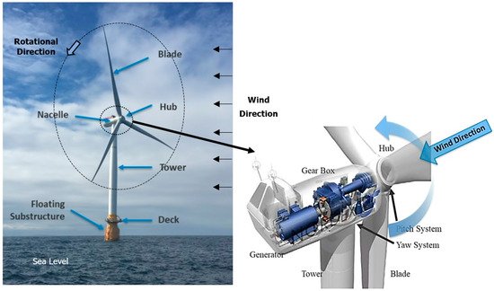
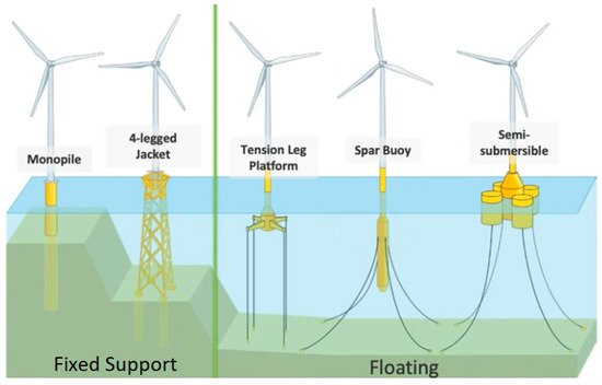
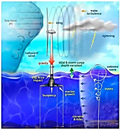
Offshore wind turbines are becoming increasingly popular due to their higher wind energy harnessing capabilities and lower visual pollution. Structural integrity of offshore wind turbine and their blades’ aerodynamics are of particular importance, which can lead towards system-level optimal design and operation, leading to reduced maintenance costs.
- floating offshore wind turbine (FOWT)
- computational fluid dynamics (CFD)
- Reynolds-Averaged Navier-Stoke (RANS)
- structural integrity
1. Introduction
2. Flow Characterization of Offshore Wind Turbines
2.1. Excitation of Foundation Platforms


2.2. Numerical Modeling for Control Design
2.3. Offshore Wind Turbine Farms
2.4. Flow Induced Acoustics
3. Structural Integrity of Offshore Wind Turbines
3.1. Wind Turbine Blades
3.2. Offshore Wind Turbine Substructure
3.3. Wind Turbine Tower
4. Offshore Wind Turbines’ Maintenance
Corrective and proactive maintenance are widely used maintenance strategies to keep the wind turbine operating and reduce downtime by monitoring their health condition. Corrective maintenance is simple and only implemented once after failure. However, it is not efficient due to a high risk of failed components, leading to severe outcomes. Therefore, time-based preventive maintenance (PM) or condition-based maintenance (CBM) is preferred over corrective maintenance in the offshore wind industry. Reliability is a critical factor for maintenance as low levels of component reliability could lead towards systems failure and extensive maintenance. The choice of correct maintenance strategy is important to maintain constant power generation with minimum downtime, improve performance of offshore wind turbines and reduce total levelized cost of energy (LCoE) [107,108,109]. Kang et al. [110] reviewed condition-based maintenance strategies for offshore wind energy and presented a summary of existing optimization solutions and maintenance strategies. It has been found that simulation models and intelligence-based solution techniques are widely used and show potential for condition recognition and optimization of offshore wind farm maintenance activities. The operation and maintenance costs of offshore wind farms are higher compared to onshore ones due to difficulty to estimate the actual costs over time. It has been suggested that minimum cost, maximum power generation and maximum availability are three drivers for optimization of maintenance techniques. Due to advancements in electrical and electronic systems for monitoring and analyzing the health of offshore structures, condition-based maintenance is expanding its applications to offshore wind energy sector. Structural health monitoring, acoustic emission testing and vibrations analysis are effective ways to monitor the condition of offshore turbine blades and structures [111].
Dao et al. [112] have proposed an integrated maintenance strategy for offshore wind turbine components by comparing different maintenance strategies. It has been observed that the maintenance downtime due to repairs and delays due to weather conditions have not been considered in previous research studies for condition-based maintenance optimization. The downtime of offshore turbines is approximately double compared to onshore wind turbines due to operating environment, adverse weather conditions and accessibility [107]. The proposed CBMPM strategy reduces the total maintenance cost and downtime of the wind turbine through numerical simulations.
Optimum system reliability of offshore wind turbines depends on a detailed maintenance plan, though maintenance scheduling is complex and challenging [115]. Nguyen and Chou [116] have found a major gap in existing literature on the maintenance schedule of wind turbines. Parameters, such as system reliability, weather conditions, maintenance duration and power generation loss, have been included in the study and the outcome for an individual and grouping maintenance schedules for offshore wind systems investigated. Reduced maintenance costs and improved systems reliability have been obtained for grouping maintenance schedules compared to the baseline schedule, hence the potential for large scale deployment of offshore wind installation in the future. Zhou and Yin [117] have stated the importance of accuracy and comprehensiveness of the maintenance information on maintenance decisions, which have the potential to cause over or under-maintenance of wind turbine components, resulting in increased maintenance costs. A dynamic opportunistic condition-based maintenance strategy has been proposed, integrating predictive analytics to develop optimal maintenance plans for turbine components. Simulation results show that the proposed strategy reduces the maintenance cost by approximately 32.46–39.24% compared to widely used maintenance strategies.
[1][2][3][4][5][6][7][8][9][10][11][12][13][14][15][16][17][18][19][20][21][22][23][24][25][26][27][28][29][30][31][32][33][34][35][36][37][38][39][40][41][42][43][44][45][46][47][48][49][50][51][52][53][54][55][56][57][58][59][60][61][62][63][64][65][66][67][68][69][70][71][72][73][74][75][76][77][78][79][80][81][82][83][84][85][86][87][88][89][90][91][92][93][94][95][96][97][98][99][100][101][102][103][104][105][106][107][108][109][110][111][112][113][114][115][116][117][118][119]
This entry is adapted from the peer-reviewed paper 10.3390/en15020579
References
- Musial, W. Overview of floating offshore wind; Webinar hosted by National Renewable Energy Laboratory, USA, 26th Feb 2020.
- Offshore wind industry review of GBs: Identifying the key barriers to large scale commercialization of gravity-based structures in the offshore wind industry. Technical report prepared by the Carbon trust and submitted to the Scottish Gov-ernment, November 2015.
- Bae, Y.H. Kim, M.H. and Kim, H.C. Performance changes of a floating offshore wind turbine with broken mooring line. Renewable Energy 2017, 101, 364-375.
- Gupta, A. and Srishti, A. Offshore wind energy market, 2027. Technical report prepared by Global Market Insights, November 2021.
- Assets publicly shared by Equinor; https://communicationtoolbox.equinor.com/shared/assets/fd892bb52c744f66a669?_ga=2.163236607.252504396.1634466588-1970887725.1632774422; accessed 17th Oct 2021.
- Stehly, T. and Beiter, P. 2018 cost of wind energy review. Technical report no. NREL/TP-5000-74598, National Renewable Energy Lab, USA, 2020.
- Beiter, P. Musial, W. Smith, A. Kilcher, L. Damiani, R. Maness, M. Sirnivas, S. Stehly, T. and Gevorgian, V. A spatial-economic cost reduction pathway analysis for US offshore wind energy development from 2015-2030. Technical report no. NREL/TP-6A20-66579, National Renewable Energy Lab, USA, 2016.
- Wiser, R. Rand, J. Seel, J. Beiter, P.B. Baker, E. Lantz, E. and Gilman, P. Expert elicitation survey predicts 37% to 49% declines in wind energy costs by 2050. Nature Energy 2021, 6, 555–565.
- Röckmann, C. Lagerveld, S. and Stavenuiter, J. Operation and Maintenance Costs of Offshore Wind Farms and Potential Multi-use Platforms in the Dutch North Sea; In Buck, B. and Langan, R. Aquaculture Perspective of Multi-Use Sites in the Open Ocean; Springer, 2017.
- Oguz, E. Clelland, D. Day, A.H. Incecik, A. López, J.A. Sánchez, G. and Almeria, G.G. Experimental and numerical analysis of a TLP floating offshore wind turbine. Ocean Engineering 2018, 147, 591-605.
- Zhou, Y. Ning, D. Shi, W. Johanning, L. and Liang, D. Hydrodynamic investigation on an OWC wave energy converter in-tegrated into an offshore wind turbine monopile. Coastal Engineering 2020, 162, 103731.
- Jang, H.K. Park, S. Kim, M.H. Kim, K.H. and Hong, K. Effects of heave plates on the global performance of a multi-unit floating offshore wind turbine. Renewable Energy 2019, 134, 526-537.
- Liu, Y. Xiao, Q. Incecik, A. and Peyrard, C. Aeroelastic analysis of a floating offshore wind turbine in platform‐induced surge motion using a fully coupled CFD‐MBD method. Wind Energy 2019, 22, 1-20.
- Kyle, R. Lee, Y.C. and Früh, W.G. Propeller and vortex ring state for floating offshore wind turbines during surge. Renewable Energy 2020, 155, 645-657.
- Shi, W. Jiang, J. Sun, K. and Ju, Q. Aerodynamic performance of semi-submersible floating wind turbine under pitch motion. Sustainable Energy Technologies and Assessments 2021, 48, 101556.
- Lei, H. Zhou, D. Bao, Y. Chen, C. Ma, N. and Han, Z. Numerical simulations of the unsteady aerodynamics of a floating vertical axis wind turbine in surge motion. Energy 2017, 127, 1-17.
- Lei, H. Zhou, D. Lu, J. Chen, C. Han, Z. and Bao, Y. The impact of pitch motion of a platform on the aerodynamic performance of a floating vertical axis wind turbine. Energy 2017, 119, 369-383.
- Lei, H. Su, J. Bao, Y. Chen, Y. Han, Z. and Zhou, D. Investigation of wake characteristics for the offshore floating vertical axis wind turbines in pitch and surge motions of platforms. Energy 2019, 166, 471-489.
- Liu, Y. Xiao, Q. Incecik, A. Peyrard, C. and Wan, D. Establishing a fully coupled CFD analysis tool for floating offshore wind turbines. Renewable Energy 2017, 112, 280-301.
- Bashetty, S. and Ozcelik, S. Review on Dynamics of Offshore Floating Wind Turbine Platforms. Energies 2021, 14, 6026.
- Chen, J. Hu, Z. Liu, G. and Wan, D. Coupled aero-hydro-servo-elastic methods for floating wind turbines. Renewable Energy 2019, 130, 139-153.
- Morison, J.R. Johnson, J.W. and Schaaf, S.A. The force exerted by surface waves on piles. Journal of Petroleum Technology 1950, 2, 149-154.
- Dafnakis, P. Bhalla, A.P.S Sirigu, S.A. Bonfanti, M. Bracco, G. and Mattiazzo, G. Comparison of wave–structure interaction dynamics of a submerged cylindrical point absorber with three degrees of freedom using potential flow and computational fluid dynamics models. Physics of Fluids 2020, 32, 093307.
- Rezaeiha, A. and Micallef, D. Wake interactions of two tandem floating offshore wind turbines: CFD analysis using actuator disc model. Renewable Energy 2021, 179, 859-876.
- Cheng, P. Huang, Y. and Wan, D. A numerical model for fully coupled aero-hydrodynamic analysis of floating offshore wind turbine. Ocean Engineering 2018, 173, 183-196.
- Cormier, M. Caboni, M. Lutz, T. Boorsma, K. and Krämer, E. Numerical analysis of unsteady aerodynamics of floating offshore wind turbines. Journal of Physics: Conference Series 2018, 1037, 072048.
- Naderi, S. Parvanehmasiha, S. and Torabi, F. Modeling of horizontal axis wind turbine wakes in Horns Rev offshore wind farm using an improved actuator disc model coupled with computational fluid dynamic. Energy Conversion and Management 2018, 171, 953-968.
- Richmond, M. Antoniadis, A. Wang, L. Kolios, A. Al-Sanad, S. and Parol, J. Evaluation of an offshore wind farm computational fluid dynamics model against operational site data. Ocean Engineering 2019, 193, 106579.
- Tran, T.T. and Kim, D.H. A CFD study of coupled aerodynamic‐hydrodynamic loads on a semisubmersible floating offshore wind turbine. Wind Energy 2018, 21, 70-85.
- Gargallo-Peiró, A. Avila, M. Owen, H. Prieto-Godino, L. and Folch, A. Mesh generation, sizing and convergence for onshore and offshore wind farm Atmospheric Boundary Layer flow simulation with actuator discs. Journal of Computational Physics 2018, 375, 209-227.
- Li, L. Huang, Z. Ge, M. and Zhang, Q. A novel three-dimensional analytical model of the added streamwise turbulence in-tensity for wind-turbine wakes. Energy 2022, 238, 121806.
- Fang, Y. Duan, L. Han, Z. Zhao, Y. and Yang, H. Numerical analysis of aerodynamic performance of a floating offshore wind turbine under pitch motion. Energy 2020, 192, 116621.
- Bangga, G. Guma, G. Lutz, T. and Krämer, E. Numerical simulations of a large offshore wind turbine exposed to turbulent inflow conditions. Wind Engineering 2018, 42, 88-96.
- Liu, Y. Chen, D. and Li, S. The artificial generation of the equilibrium marine atmospheric boundary layer for the CFD simulation of offshore wind turbines. Journal of Wind Engineering and Industrial Aerodynamics 2018, 183, 44-54.
- Li, L. Liu, Y. Yuan, Z. and Gao, Y. Wind field effect on the power generation and aerodynamic performance of offshore floating wind turbines. Energy 2018, 157, 379-390.
- Zhou, Y. Xiao, Q. Liu, Y. Incecik, A. Peyrard, C. Wan, D. and Li, S. A CFD study for floating offshore wind turbine aerodynamics in turbulent wind field, Proceedings of the ASME 3rd International Offshore Wind Technical Conference, online, 16-17 February 2021.
- Sirnivas, S. Musial, W. Bailey, B. and Filippelli, M. Assessment of offshore wind system design, safety, and operation standards. Technical report no. NREL/TP-5000-60573, National Renewable Energy Lab, USA, 2014.
- Wen, B. Tian, X. Dong, X. Peng, Z. Zhang, W. and Wei, K. A numerical study on the angle of attack to the blade of a hori-zontal-axis offshore floating wind turbine under static and dynamic yawed conditions. Energy 2019, 168, 1138-1156.
- Shen, X. Chen, J. Hu, P. Zhu, X. and Du, Z. Study of the unsteady aerodynamics of floating wind turbines. Energy 2018, 145, 793-809.
- Dong, J. and Viré, A. Comparative analysis of different criteria for the prediction of vortex ring state of floating offshore wind turbines. Renewable Energy 2021, 163, 882-909.
- Wen, B. Beng, X. Tian, X. Peng, Z. Zhang, W. and Wei, K. The power performance of an offshore floating wind turbine in platform pitching motion. Energy 2018, 154, 508-521.
- Wen, B. Tian, X. Dong, X. Peng, Z. and Zhang, W. Influences of surge motion on the power and thrust characteristics of an offshore floating wind turbine. Energy 2017, 141, 2054-2068.
- Bruinsma, N. Paulsen, B.T. and Jacobsen, N.G. Validation and application of a fully nonlinear numerical wave tank for sim-ulating floating offshore wind turbines. Ocean Engineering 2018, 147, 647-658.
- Lee, H. and Lee, D.J. Effects of platform motions on aerodynamic performance and unsteady wake evolution of a floating offshore wind turbine. Renewable Energy 2019, 143, 9-23.
- Zhang, Y. and Kim, B. A fully coupled computational fluid dynamics method for analysis of semi-submersible floating off-shore wind turbines under wind-wave excitation conditions based on OC5 data. Applied Sciences 2018, 8, 2314.
- Lin, L. Wang, K. and Vassalos, D. Detecting wake performance of floating offshore wind turbine. Ocean Engineering 2018, 156, 263-276.
- Chen, Z. Wang, X. Guo, Y. and Kang, S. Numerical analysis of unsteady aerodynamic performance of floating offshore wind turbine under platform surge and pitch motions. Renewable Energy 2021, 163, 1849-1870.
- Jonkman, J.M. Dynamics of offshore floating wind turbines—model development and verification. Wind Energy 2009, 12, 459-492.
- Coulling, A.J. Goupee1, A.J Robertson, A.N. Jonkman, J.M. and Dagher, H.J. Validation of a FAST semi-submersible floating wind turbine numerical model with DeepCwind test data. Journal of Renewable and Sustainable Energy 2013, 5, 023116.
- Lienard, C. Boisard, R. and Daudin, C. Aerodynamic behavior of a floating offshore wind turbine. American Institute of Aer-onautics and Astronautics Journal 2020, 58, 3835-3847.
- Lemmer, F. Yu, W. and Cheng, P.W. Iterative frequency-domain response of floating offshore wind turbines with parametric drag. Journal of Marine Science and Engineering 2018, 6, 118.
- Zhang, P. Yang, S. Li, Y. Gu, J. Hu, Z. Zhang, R. and Tang, Y. Dynamic Response of Articulated Offshore Wind Turbines under Different Water Depths. Energies 2020, 13, 2784.
- Chuang, Z. Liu, S. and Lu, Y. Influence of second order wave excitation loads on coupled response of an offshore floating wind turbine. International Journal of Naval Architecture and Ocean Engineering 2020, 12, 367-375.
- Alkarem, Y.R. and Ozbahceci, B.O. A complemental analysis of wave irregularity effect on the hydrodynamic response of offshore wind turbine with the semi-submersible platform. Applied Ocean Research 2021, 113, 102757.
- Li, H. and Bachynski-Polić, E.E. Validation and application of nonlinear hydrodynamics from CFD in an engineering model of a semi-submersible floating wind turbine. Marine Structures 2021, 79, 103054.
- Wang, L. Robertson, A. Jonkman, J. Yu, Y. Koop, A. Borràs Nadal, A. Li, H. Shi, W. Pinguet, R. Zhou, Y. Xiao, Q. Kumar, R. and Sarlak, H. Investigation of nonlinear difference-frequency wave excitation on a semisubmersible offshore-wind platform with bichromatic-wave CFD simulations, Proceedings of the ASME 3rd International Offshore Wind Technical Conference, online, 16-17 February 2021.
- Martini, F. Montoya, L.T.C. and Ilinca, A. Review of wind turbine icing modelling approaches. Energies 2021, 14, 5207.
- Yue, W. Xue, Y. and Liu, Y. High humidity aerodynamic effects study on offshore wind turbine airfoil/blade performance through CFD analysis. International Journal of Rotating Machinery 2017, 2017.
- Lagdani, O. Tarfaoui, M. Nachtane, M. Trihi, M. and Laaouidi, H. A numerical investigation of the effects of ice accretion on the aerodynamic and structural behavior of offshore wind turbine blade. Wind Engineering 2021, 45, 1433-1446.
- Fleming, P.A. Gebraad, P.M. Lee, S. van Wingerden, J.W. Johnson, K. Churchfield, M. Michalakes, J. Spalart, P. and Moriarty, P. Evaluating techniques for redirecting turbine wakes using SOWFA. Renewable Energy 2014, 70, 211-218.
- Fleming, P.A. Gebraad, P.M. Lee, S. van Wingerden, J.W. Johnson, K. Churchfield, M. Michalakes, J. Spalart, P. and Moriarty, P. Simulation comparison of wake mitigation control strategies for a two‐turbine case. Wind Energy 2015, 18, 2135-2143.
- Fleming, P. Annoni, J. Shah, J.J. Wang, L. Ananthan, S. Zhang, Z. Hutchings, K. Wang, P. Chen, W. and Chen, L. Field test of wake steering at an offshore wind farm. Wind Energy Science 2017, 2, 229-239.
- Sang, L.Q. Li, Q. Cai, C. Maeda, T. Kamada, Y. Wang, X. Zhou, S. and Zhang, F. Wind tunnel and numerical study of a floating offshore wind turbine based on the cyclic pitch control. Renewable Energy 2021, 172, 453-464.
- Whittlesey, R.W. Liska, S. and Dabiri, J.O. Fish schooling as a basis for vertical axis wind turbine farm design. Bioinspiration and Biomimetics 2010, 5, 035005.
- Zhang, M. Arendshorst, M.G. and Stevens, R.J. Large eddy simulations of the effect of vertical staggering in large wind farms. Wind Energy 2019, 22, 189-204.
- Neunaber, I. Hölling, M. Stevens, R.J. Schepers, G. and Peinke, J. Distinct turbulent regions in the wake of a wind turbine and their inflow-dependent locations: the creation of a wake map. Energies 2020, 13, 5392.
- Wang, Y. Miao, W. Ding, Q. Li, C. and Xiang, B. Numerical investigations on control strategies of wake deviation for large wind turbines in an offshore wind farm. Ocean Engineering 2019, 173, 794-801.
- Klein, L. Gude, J. Wenz, F. Lutz, T. and Krämer, E. Advanced computational fluid dynamics (CFD)–multi-body simulation (MBS) coupling to assess low-frequency emissions from wind turbines. Wind Energy Science 2018, 3, 713-728.
- May, R. Nygård, T. Falkdalen, U. Åström, J. Hamre, Ø. and Stokke, B.G. Paint it black: Efficacy of increased wind turbine rotor blade visibility to reduce avian fatalities. Ecology and Evolution 2020, 10, 8927-8935.
- Boudounit, H. Tarfaoui, M. Saifaoui, D. and Nachtane, M. Structural analysis of offshore wind turbine blades using finite element method. Wind Engineering 2019, 44, 168-180.
- Hashin, Z. Failure criteria for unidirectional fiber composites. Journal of Applied Mechanics 1980, 47, 329-334.
- Hashin, Z. and Rotem, A. A fatigue failure criterion for fiber reinforced materials. Journal of Composite Materials 1973, 7, 448-464.
- Hand, B. Kelly, G. and Cashman, A. Structural analysis of an offshore vertical axis wind turbine composite blade experiencing an extreme wind load. Marine Structures 2021, 75, 102858.
- International Standard. Wind Turbines – Part 1: Design Requirements. IEC 61400-1, 3rd ed. 2005.
- Finnegan, W. Jiang, Y. Dumergue, N. Davies, P. and Goggins, J. Investigation and validation of numerical models for com-posite wind turbine blades. Journal of Marine Science and Engineering 2021, 9, 525.
- Finnegan, W. Keeryadath, P.D. Coistealbha, R.O. Flanagan, T. Flanagan, M. and Goggins, J. Development of a numerical model of a novel leading edge protection component for wind turbine blades. Wind Energy Science 2020, 5, 1567-1577.
- Finnegan, W. Flanagan, T. and Goggins, J. Development of a novel solution for leading edge erosion on offshore wind turbine blades, Proceedings of the 13th International Conference on Damage Assessment of Structures, Porto, Portugal, 9-10 July 2019.
- Fagan, E.M. Flanagan, M. Leen, S.B. Flanagan, T. Doyle, A. and Goggins, J. Physical experimental static testing and structural design optimisation for a composite wind turbine blade. Composite Structures 2017, 164, 90-103.
- Navadeh, N. Goroshko, I. Zhuk, Y. Etminan, Moghadam, F.E. and Fallah, A.S. Finite element analysis of wind turbine blade vibrations. Vibration 2021, 4, 310-322.
- Ali, A. Risi, R.D. and Sextos, A. Finite element modelling optimization of wind turbine blades from an earthquake engineering perspective. Engineering Structures 2020, 222, 111105.
- Oh, S. and Ishihara, T. Structural parameter identification of a 2.4 MW bottom fixed wind turbine by excitation test using active mass damper. Wind Energy 2018, 21, 1232-1238.
- Ishihara, T. and Wang, L. A study of modal damping for offshore wind turbines considering soil properties and foundation types. Wind Energy 2019, 22, 1760-1778.
- Gentils, T. Wang, L. and Kolios, A. Integrated structural optimisation of offshore wind turbine support structures based on finite element analysis and genetic algorithm. Applied Energy 2017, 199, 187-204.
- Ram, S.L. and Mohana, R. Simulation and numerical analysis of offshore wind turbine with monopile foundation. Journal of Physics Conference Series: Materials Science and Engineering 2020, 872, 012046.
- Det Norske Vertias. Design of offshore wind turbine structures. Offshore Standard DNV-OS-J101, 2014.
- Luengo, M.M. Kolios, A. and Wang, L. Parametric FEA modelling of offshore wind turbine support structures: Towards scaling-up and CAPEX reduction. International Journal of Marine Energy 2017, 19, 16-31.
- Ma, H. Yang, J. and Chen, L. Effect of scour on the structural response of an offshore wind turbine supported on tripod foundation. Applied Ocean Research 2018, 73, 179-189.
- The National Basic Research Program of China (2014CB046200) Annual Report, Nan Jing University of Aeronautics and As-tronautics, China, 2015.
- Stahlmann, A. Experimental and numerical modeling of scour at offshore wind turbines. PhD thesis, Leibniz University, Hannover, Germany, 2013.
- Stuyts, B. and Cathie, D. Scour assessment and measurement for pile-supported wind turbine foundations, Proceedings of the 32nd International Conference on Ocean, Offshore and Arctic Engineering, Nantes, France, 2013.
- Shittu, A.A. Mehmanparast, A. Shafiee, M. Kolios, A. Hart, P and Pilario, K. Structural reliability assessment of offshore wind turbine support structures subjected to pitting corrosion-fatigue: A damage tolerance modelling approach. Wind Energy 2020, 23, 2004-2026.
- Ghigo, A. Cottura, L. Caradonna, R. Bracco, G. and Mattiazzo, G. Platform optimization and cost analysis in a floating offshore wind farm. Journal of Marine Science and Engineering 2020, 8, 835.
- Techet, A.H. Hydrodynamics for Ocean Engineers. Cambridge, USA, 2004.
- Xu, K. Larsen, K. Shao, Y. Zhang, M. Gao, Z. and Moan, T. Design and comparative analysis of alternative mooring systems for floating wind turbines in shallow water with emphasis on ultimate limit state design. Ocean Engineering 2021, 219, 108377.
- Huang, W.H. and Yang, R.Y. Water depth variation influence on the mooring line design for FOWT within shallow water region. Journal of Marine Science and Engineering 2021, 9, 409.
- Li, Y. Le, C. Ding, H. Zhang, P. and Zhang, J. Dynamic response for a submerged floating offshore wind turbine with different mooring configurations. Journal of Marine Science and Engineering 2019, 7, 115.
- Dagli, B.Y. Tuskan, Y. and Gokkus, U. Evaluation of offshore wind turbine tower dynamics with numerical analysis. Advances in Civil Engineering 2018, 3054851.
- Asnaashari, E. Morris, A. Andrew, I. Hahn, W. and Sinha, J.K. Finite element modelling and in-situ modal testing of an offshore wind turbine. Journal of Vibration Engineering and Technologies 2018, 6, 101-106.
- Ko, Y.Y. A simplified structural model for monopile-supported offshore wind turbines with tapered towers. Renewable Energy 2020, 156, 777-790.
- Feliciano, J. Cortina, G. Spear, A. and Calaf, M. Generalized analytical displacement model for wind turbine towers under aerodynamic loading. Journal of Wind Engineering and Industrial Aerodynamics 2018, 176, 120-130.
- Kim, W. Yi, J.H. Kim, J.T. and Park, J.H. Vibration-based structural health assessment of a wind turbine tower using a wind turbine model. Procedia Engineering 2017, 188, 333-339.
- Liu, W. Design and kinetic analysis of wind turbine blade-hub-tower coupled system. Renewable Energy 2016, 94, 547-557.
- Chen, J. Yang, R. Ma, R. and Li, J. Design optimization of wind turbine tower with lattice-tubular hybrid structure using particle swarm algorithm. The Structural Design of Tall and Special Buildings 2016, 25, 743-758.
- Germanischer Lloyd and Wind Energy Committee. Guideline for the certification of wind turbines. Rules and Guidelines Industrial Services. 2010.
- National Standard of The People’s Republic of China. Load Code for the Design of Buildings. GB 50009. 2012.
- G+ Global Offshore Wind Health and Safety Organization: 2020 incident data report.
- Dao, C.D. Kazemtabrizi, B. and Crabtree, C.J. Wind turbine reliability data review and impacts on levelized cost of energy. Wind Energy 2019, 22, 1848-1871.
- Carroll, J. McDonald, A. and McMillan, D. Failure rate, repair time and unscheduled O&M cost analysis of offshore wind turbines. Wind Energy 2016, 19, 1107-1119.
- Reder, M.D. Gonzalez, E. and Melero, J.J. Wind turbine failures - tackling current problems in failure data analysis. Journal of Physics Conference Series 2016, 753, 072027.
- Kang, J. Sobral, J. and Soares, C.G. Review of condition-based maintenance strategies for offshore wind energy. Journal of Marine Science Application 2019, 18, 1-16.
- Liu, K. Yan, R.J. and Soares, C.G. Damage identification in offshore jacket structures based on modal flexibility. Ocean Engi-neering 2018, 170, 171-185.
- Dao, C.D. Kazemtabrizi, B. Crabtree, C.J. and Tavner, P.J. Integrated condition‐based maintenance modelling and optimisa-tion for offshore wind turbines. Wind Energy 2021.
- Florian, M. and Sørensen, J.D. Risk-based planning of operation and maintenance for offshore wind farms. Energy Procedia 2017, 137, 261-272.
- Ambühl, S. and Sørensen, J.D. Sensitivity of risk-based maintenance planning of offshore wind turbine farms. Energies 2017, 10, 505.
- Shafiee M. Maintenance logistics organization for offshore wind energy: current progress and future perspectives. Renew Energy 2015, 77, 182-93.
- Nguyen, T.A.T. and Chou, S.Y. Maintenance strategy selection for improving cost-effectiveness of offshore wind systems. Energy Conversion and Management 2018, 157, 86-95.
- Zhou, P. and Yin, P.T. An opportunistic condition-based maintenance strategy for offshore wind farm based on predictive analytics. Renewable and Sustainable Energy Reviews 2019, 109, 1-9.
- Li, M. Wang, M. Kang, J. Sun, L. and Jin, P. An opportunistic maintenance strategy for offshore wind turbine system considering optimal maintenance intervals of subsystems. Ocean Engineering 2020, 216, 108067.
- Lu, Y. Sun, L. Zhang, X. Feng, F. Kang, J. and Fu, G. Condition based maintenance optimization for offshore wind turbine considering opportunities based on neural network approach. Applied Ocean Research 2018, 74, 69-79.
