Your browser does not fully support modern features. Please upgrade for a smoother experience.
Submitted Successfully!
 +1 credit
Thank you for your contribution! You can also upload a video entry or images related to this topic.
For video creation, please contact our Academic Video Service.
| Version | Summary | Created by | Modification | Content Size | Created at | Operation |
|---|---|---|---|---|---|---|
| 1 | chuanyang Lu | + 993 word(s) | 993 | 2022-01-04 09:24:01 | | | |
| 2 | chuanyang Lu | + 749 word(s) | 1742 | 2022-01-14 02:23:49 | | | | |
| 3 | Rita Xu | + 384 word(s) | 2126 | 2022-01-14 09:00:47 | | |
Video Upload Options
We provide professional Academic Video Service to translate complex research into visually appealing presentations. Would you like to try it?
Cite
If you have any further questions, please contact Encyclopedia Editorial Office.
Lu, C. Electrically Excited Doubly Salient Variable Reluctance Machine. Encyclopedia. Available online: https://encyclopedia.pub/entry/18227 (accessed on 24 July 2026).
Lu C. Electrically Excited Doubly Salient Variable Reluctance Machine. Encyclopedia. Available at: https://encyclopedia.pub/entry/18227. Accessed July 24, 2026.
Lu, Chuanyang. "Electrically Excited Doubly Salient Variable Reluctance Machine" Encyclopedia, https://encyclopedia.pub/entry/18227 (accessed July 24, 2026).
Lu, C. (2022, January 14). Electrically Excited Doubly Salient Variable Reluctance Machine. In Encyclopedia. https://encyclopedia.pub/entry/18227
Lu, Chuanyang. "Electrically Excited Doubly Salient Variable Reluctance Machine." Encyclopedia. Web. 14 January, 2022.
Copy Citation
The Electrically Excited Doubly Salient Variable Reluctance Machine (EEDSVRM) is a new type of brushless machine designed according to the principle of air gap reluctance change.
Electrically Excited Doubly Salient Variable Reluctance Machine (EEDSVRM)
machine topology
1. Introduction
Traditional machine excitation sources are concentrated on the rotor, such as the permanent magnet synchronous machine (PMSM), which has a higher power density and efficiency, has attracted much attention, and has been widely used [1]. However, the permanent magnets placed on the rotor usually need to take special reinforcement measures to overcome the centrifugal force during high-speed operation, which leads to a complex machine structure and high manufacturing cost [2]. Moreover, the poor heat dissipation capacity of the machine leads to an increase in the surface temperature of the rotor, which may cause irreversible demagnetization of the permanent magnets. The typical stator electric exciter machine represented by EEDSVRM has received more and more attention in recent years because of its solid structure and high robustness.
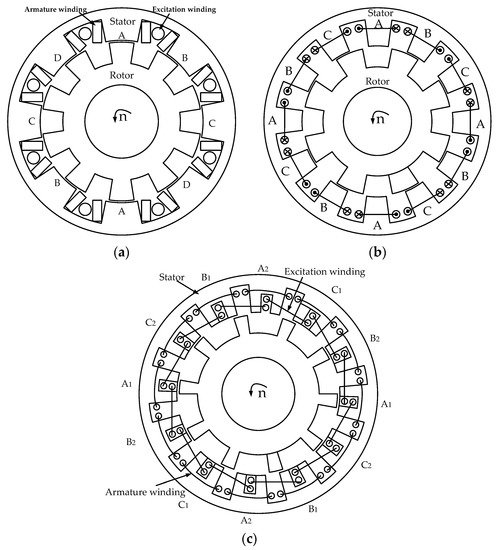
There are two kinds of Variable Reluctance Machines (VRMs): unilateral salient pole and bilateral salient pole. The bilateral salient pole VRM is more popular due to its many advantages, such as the largest ratio of maximum to minimum reluctance and better electromechanical energy conversion characteristics. There are three types of EEDSVRM, namely the Wound-field Doubly Salient Machine (WFDSM) [3], Switched Reluctance Machine (SRM) [4], and Electrical Excitation Flux-switching Machine (EEFSM) [5], as shown in Figure 1.
In recent years, EEDSVRM have attracted increasing attention and become one of the research highlights in the machine field. In [6][7][8][9][10][11][12], the control strategy research for EEDSVRM is proposed. Traditional position sensors have many inherent disadvantages, such as increasing the cost of the drive system and reducing the robustness of the machine. In order to improve the overall stability of the WFDSM, a position sensorless control strategy that adopts the relationship between the machine’s self-inductance and the rotor position to estimate the rotor position is applied to the WFDSM [6][7]. Aiming at the problem of large torque ripple that is inherent in VRM, an instantaneous torque control strategy incorporating the adaptive terminal sliding mode to suppress SRM torque ripple is proposed [8][9]. An improved direct instantaneous torque control method of the 12/8-pole WFDSM drive system has been researched. The application of this control strategy can reduce the torque ripple of the WFDSM and improve the torque output capability effectively [10]. In [11], a new of fault-tolerant control strategy is proposed for the fault of the power converter. Simulation results show that the proposed fault-tolerant control strategy can effectively alleviate the output performance degradation of WFDSM, caused by power converter failure. In [12], the sliding mode control was applied to the flux-switching machine (FSM), which can improve the stability of the FSM drive system. In [13], the fault characteristics of short circuit and open circuit faults for EEFSM were studied. By changing the switching state of the power transistor, a basic three closed-loop fault-tolerant control strategy based on speed, winding, and current and short-circuit current can be achieved. A fault diagnosis method based on wavelet packet decomposition was introduced for SRM [14]. The power converter fault diagnosis for WFDSM is proposed in [15]. The control strategy is widely used in VRM as it suppresses the torque ripple, which makes the torque smoother and the overall robustness of VRM improved.
As a new electric excitation machine, EEDSVRM is widely used in popular fields such as aerospace and electric vehicles because of its simple structure and high robustness. However, due to its structural characteristics, VRM has problems such as excessive torque pulsation, which affects operating performance. Therefore, it is necessary to consider the machine structure and optimize the design of the machine to find the optimal combination of structural parameters to make the EEDSVRM achieve the best operating performance, which is of great benefit to the large-scale application of VRM in industry. The optimization design of EEDSVRM ontology was researched in [16][17][18][19][20][21]. There are many types of EEDSVRM ontology optimization designs, which can be roughly divided into five types: novel machine topology-based optimization, finite element simulation-based optimization, mathematical analysis-based optimization, intelligent algorithm-based optimization, and multiple fusion-based optimization. These five optimization design methods have their own characteristics. It is relatively time-consuming to propose new machine topology optimization and finite element optimization. Although mathematical formula analysis meets the requirements of real-time optimization, the optimization accuracy is still insufficient compared to finite element. Multi-objective optimization using intelligent algorithms can improve optimization efficiency. The optimization method of multiple fusion combines the advantages of multiple optimization methods and greatly improves the optimization efficiency as well as reduces the optimization cost.
2. Basic Topologies, Principles, and Performances
2.1. WFDSM
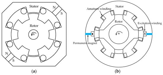
According to the machine excitation mode, the Doubly Salient Machine (DSM) can be divided into three categories, as follows: the Wound-field Doubly Salient Machine (WFDSM), which is shown in Figure 1a; the Doubly Salient Permanent Magnet Machine (DSPM); and the Hybrid Excitation Doubly Salient Machine (HEDSM), as shown in Figure 2 [22][23][24]. Compared with DSPM and HEDSM, WFDSM does not use permanent magnets for excitation. Instead, it only relies on the DC power supply to provide the excitation source. In this way, the magnetic flux of the machine can be controlled by adjusting the amplitude of the excitation current and the risk of irreversible demagnetization of the machine can be avoided. Therefore, the WFDSM can be used in harsh environments and has a strong magnetic flux adjustment capability.
The working mode of WFDSM is different from DSPM and HEDSM, which adopt permanent magnet excitation because of the DC excitation mode. When current flows into the excitation winding, a magnetic field is established inside the machine. The magnetic flux generated by the main magnetic field passes through the yoke and magnetic poles of the stator and rotor and penetrates the entire magnetic circuit of the machine. When the machine rotor is driven to rotate by the prime mover, the flux linkage of the armature winding changes with the rotor position, resulting in a symmetrically induced potential. Unlike the permanent magnet excitation, the air gap magnetic field remains constant, which results in poor output voltage regulation and fault demagnetization capabilities. In WFDSM, the main magnetic flux of the machine can be controlled by adjusting the excitation current to affect the output voltage. The external uncontrollable rectifier circuit is shown in Figure 3 [25], where eAf, eBf, eCf, and eDf are the induced voltages of windings A, B, C, and D; WA, WB, WC, and WD are the windings A, B, C and D; RA, RB, RC, and RD are the self-resistance of the armature windings of A, B, C, and D; and R is the external load.
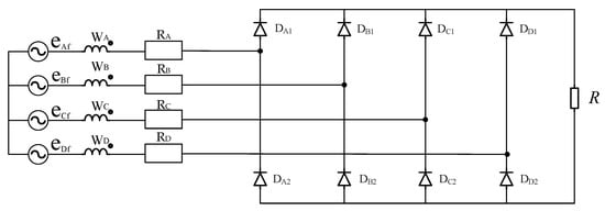
Figure 3. Full bridge rectifier circuit [25].
2.2. SRM
The stator and rotor of SRM are salient pole structures. As shown in Figure 1b, the salient pole of the stator is wound with armature winding, while there is no excitation winding. The magnetic flux moves along the path of minimum reluctance. When the stator and rotor poles are aligned, the air gap reluctance is the smallest. On the contrary, when the cogging is aligned, the air gap reluctance of the machine is the largest. Therefore, SRM follows the principle of minimum reluctance and the magnetic field is distorted to produce electromagnetic torque. Due to its simple structure, stable operation, and wide speed regulation range, it is widely used in aerospace, electric vehicle, and other fields. SRM have two-phase, three-phase, and multi-phase structures, and the stator and rotor also have different pole slot matching combinations. Generally speaking, if the multi-phase structure is adopted, the torque ripple of SRM is relatively small [26]. The relationship between the pole slot and phase number of SRM is as follows:
(1)
where is the least common multiple of the number of poles of the stator and rotor, m is the phase number of SRM, and and represent the number of poles of the stator and rotor, respectively.
The pole slot between the stator and rotor of SRM is shown in Table 1. The most common one is the three-phase 12/8-pole machine, as shown in Figure 1b. Increasing the number of poles of SRM can reduce the torque ripple and vibration problems caused by SRM to a certain extent [27].
Table 1. Common pole slot fit combination of the stator and rotor of SRM.

2.3. EEFSM
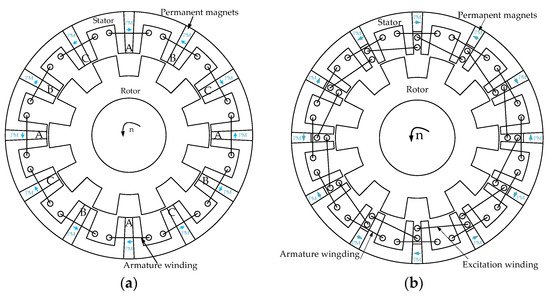
Identical to the excitation method of DSM, in addition to EEFSM that uses only direct current for excitation, FSM also includes a flux-switching permanent magnet machine (FSPM) that uses permanent magnets for excitation and a hybrid flux-switching machine (HEFSM) in which permanent magnets and direct current are used for excitation at the same time. The topology of FSPM and HEFSM are shown in Figure 4. Although FSPM is considered to be the latest stator excited reluctance machine [28], the permanent magnets used for excitation inevitably encounter demagnetization problems. It is because of the ability to achieve magnetic field adjustment and fault demagnetization under high temperature and harsh operating environments that EEFSM has attracted increasing attention and become one of the research highlights in the VRM field. Figure 1c shows the most widely used 12/10 pole for EEFSM.
As shown in Figure 1c, it can be seen that there are 12 salient pole silicon steel cores on the stator. Slots are made on the stator teeth and the field windings are embedded in them. The excitation currents of the adjacent two sets of stator slots are opposite to each other.
Compared with conventional SRM, EEFSM can work in a full cycle and both its torque density and power density are higher, which makes it more suitable for applications with high performance requirements such as aerospace and offshore wind power.
With the periodic change of the overlapping area between the rotor pole and stator teeth, the air gap magnetic conductivity in the main magnetic circuit also changes, resulting in the magnetic linkage and back electromotive force in the phase winding, changing with the rotor position, which realizes the so-called “flux switching”, as shown in Figure 5. Reasonably designing the pole slot fit of FSPM and optimizing the structural size of the machine can make the waveform of the flux linkage and back EMF close to the sine wave.
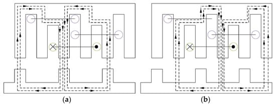
Figure 5. (a) Maximum forward position of flux linkage. (b) Maximum reverse position of flux linkage.
2.4. Dissimilarity and Commonness of the Three Kinds of Variable Reluctance Machines
The three kinds of machines belong to the category of electrically excited variable reluctance machines, which have both dissimilarities and commonness. Commonalities are described below.
- (1)
-
Electromagnetic torque is generated by the principle of minimum reluctance.
- (2)
-
The stator and rotor adopt salient pole structures, also known as a double salient pole machine. There are no windings on the rotor and both the field winding and armature winding are on the stator poles.
- (3)
-
The armature winding of the reluctance machine adopts centralized winding and uses less copper, thus the resistance of the armature winding is relatively small and the copper loss is also small.
- (4)
-
All three types of VRM are excited by DC, which avoids the irreversible demagnetization defect of permanent magnet excitation at high temperature.
Furthermore, the three EEDSVRMs of WFDSM, SRM, and EEFSM also have various characteristics. Traditional SRM can only output power when the rotor slides out of the stator poles, while WFDSM and EEFSM can be connected to either a half-bridge rectifier circuit or a full-bridge rectifier circuit. When an external half-bridge rectifier circuit is connected, it can only work when the rotor slides in or slides out of the stator poles, which can only be output in half a cycle. However, when an external full-bridge rectifier circuit is connected, WFDSM and EEFSM will output voltage whether the rotor slides in or slides out of the stator poles. The process that the rotor completes from sliding in to sliding out of the stator poles is called a full cycle. Therefore, SRM can only work in a half cycle, while WFDSM and EEFSM can output power in a full cycle. Compared with WFDSM and EEFSM, the half-cycle working mode makes SRM output power density and torque density at a relatively low rate. Both SRM and WFDSM have unipolar magnetic flux linkage, while EEFSM can switch the magnetic flux to make the magnetic flux linkage present positive and negative bipolarly. Although the excitation windings on WFDSM and EEFSM are both placed on the stator poles, there are still some differences in the placement of the windings. The excitation windings of WFDSM are directly embedded in the stator slots, while EEFSM is slotted on the stator teeth to place the excitation windings.
References
- Chau, K.T.; Chan, C.C.; Liu, C. Overview of Permanent-Magnet Brushless Drives for Electric and Hybrid Electric Vehicles. IEEE Trans. Ind. Electron. 2008, 55, 2246–2257.
- Tong, W.; Li, S.; Pan, X.; Wu, S.; Tang, R. Analytical Model for Cogging Torque Calculation in Surface-Mounted Permanent Magnet Motors with Rotor Eccentricity and Magnet Defects. IEEE Trans. Energy Convers. 2020, 35, 2191–2200.
- Zhao, Y.; Teng, D.; Li, D.; Zhao, X. Comparative Research on Four-Phase Dual Armature-Winding Wound-Field Doubly Salient Generator With Distributed Field Magnetomotive Forces for High-Reliability Application. IEEE Access 2021, 9, 12579–12591.
- Ferková, Ž.; Suchý, Ľ.; Bober, P. Comparison of 6/4 and 12/8 Switched Reluctance Motor Models Using Direct Torque Control with Torque Lookup Table. Electr. Eng. 2019, 102, 75–83.
- Gaussens, B.; Hoang, E.; Lecrivain, M.; Manfe, P.; Gabsi, M. A Hybrid-Excited Flux-Switching Machine for High-Speed DC-Alternator Applications. IEEE Trans. Ind. Electron. 2014, 61, 2976–2989.
- Zhou, X.; Zhou, B.; Wei, J. A Novel Position-Sensorless Startup Method for DSEM. IEEE Trans. Ind. Appl. 2018, 54, 6101–6109.
- Zhou, X.; Zhou, B.; Wang, K. Position Sensorless Control for Doubly Salient Electromagnetic Machine with Improved Startup Performance. IEEE Trans. Ind. Electron. 2019, 67, 1782–1791.
- Sun, X.; Feng, L.; Diao, K.; Yang, Z. An Improved Direct Instantaneous Torque Control Based on Adaptive Terminal Sliding Mode for a Segmented-Rotor SRM. IEEE Trans. Ind. Electron. 2020, 68, 10569–10579.
- Zhang, X.; Yang, Q.; Ma, M.; Lin, Z.; Yang, S. A Switched Reluctance Motor Torque Ripple Reduction Strategy with Deadbeat Current Control and Active Thermal Management. IEEE Trans. Veh. Technol. 2020, 69, 317–327.
- Chen, X.; Zhang, Z.; Yu, L.; Bian, Z. An Improved Direct Instantaneous Torque Control of Doubly Salient Electromagnetic Machine for Torque Ripple Reduction. IEEE Trans. Ind. Electron. 2021, 68, 6481–6492.
- Hu, D.; Bo, Z.; Gan, Z.; Huang, X.; Zhou, X. Research of Fault-Tolerant Strategy for Power Converter of Four-Phase Dsem Drive. In Proceedings of the 2016 19th International Conference on Electrical Machines and Systems (ICEMS), Chiba, Japan, 13–16 November 2016.
- Yuan, X.; Wei, Z.; Feng, Y.; Gu, W. Sliding Mode Control of Axial Field Flux-Switching Permanent Magnet Machine. In Proceedings of the 2017 20th International Conference on Electrical Machines and Systems (ICEMS), Sydney, NSW, Australia, 11–14 August 2017.
- Lin, F.; Chau, K.T.; Lee, C.H.T.; Liu, C. Fault Signature of a Flux-Switching DC-Field Generator. IEEE Trans. Magn. 2015, 51, 1.
- Gan, C.; Wu, J.; Yang, S.; Hu, Y.; Cao, W. Wavelet Packet Decomposition-Based Fault Diagnosis Scheme for SRM Drives with a Single Current Sensor. IEEE Trans. Energy Convers. 2015, 31, 303–313.
- Feng, X.; Zhou, B.; Zhou, X.; Ge, W.; Wang, K. A Novel Fault Diagnosis Method for Power Converter of Doubly Salient Electro-Magnetic Motor. In Proceedings of the 2019 22nd International Conference on Electrical Machines and Systems (ICEMS), Harbin, China, 11–14 August 2019.
- Pan, Z.; Fang, S.; Lin, H.; Yang, H.; Xue, S. A New Double-Sided Flux Reversal Arc Permanent Magnet Machine With Enhanced Torque Density Capability. IEEE Trans. Magn. 2019, 55, 1–6.
- Gao, Y.; Li, D.; Qu, R.; Jian, L. Design Procedure of Flux Reversal Permanent Magnet Machines. IEEE Trans. Ind. Appl. 2017, 53, 4232–4241.
- Bobba, D.; Bramerdorfer, G.; Sarlioglu, B. A Low-Pole Split Magnet Flux Switching Permanent Magnet Machine with Minimized Harmonic Distortion in Flux Linkage for High Speed Operation. In Proceedings of the 2016 XXII International Conference on Electrical Machines (ICEM), Lausanne, Switzerland, 4–7 September 2016.
- Abdeen, H.; Varró, D.; Sahraoui, H.; Nagy, A.S.; Debreceni, C.; Hegedüs, Á.; Horváth, Á. Multi-Objective Optimization in Rule-Based Design Space Exploration. In Proceedings of the 29th ACM/IEEE International Conference on Automated Software Engineering, Västerås, Sweden, 15–19 September 2014.
- Zhao, X.; Niu, S. Design and Optimization of a Novel Slot-PM-Assisted Variable Flux Reluctance Generator for Hybrid Electric Vehicles. IEEE Trans. Energy Convers. 2018, 33, 2102–2111.
- Zhao, X.; Niu, S.; Zhang, X.; Fu, W. Flux-Modulated Relieving-DC-Saturation Hybrid Reluctance Machine with Synthetic Slot-PM Excitation for Electric Vehicle In-Wheel Propulsion. IEEE Trans. Ind. Electron. 2021, 68, 6075–6086.
- Zhang, L.; Wu, L.J.; Huang, X.; Fang, Y.; Lu, Q. A Novel Structure of Doubly Salient Permanent Magnet Machine in Square Envelope. IEEE Trans. Magn. 2019, 55, 1–5.
- He, M.; Xu, W. Novel 6/7 Stator/Rotor Hybrid Excitation Doubly Salient Permanent Magnet Machine. IEEE Trans. Magn. 2016, 52, 1–5.
- Wang, S.; Zhang, X.; Zhao, X.; Niu, S.; Fu, W. A Novel Slot-PM Assisted Complementary-Rotor Doubly-Salient Machine with Enhanced Torque Performance. IEEE Trans. Ind. Electron. 2021.
- Zhao, Y.; Wang, H.; Li, D.; Qian, R. Comparative Research of a Wound-Field Doubly Salient Generator with Different Rectifiers. IEEE Trans. Ind. Inform. 2018, 14, 4851–4863.
- Wang, C.; Zhang, Z.; Liu, Y.; Geng, W.; Gao, H. Effect of Slot-Pole Combination on the Electromagnetic Performance of Ironless Stator AFPM Machine With Concentrated Windings. IEEE Trans. Energy Convers. 2020, 35, 1098–1109.
- Faiz, J.; Shahgholian, G.; Ghazizadeh, H. Analysis of Dynamic Behavior of Switched Reluctance Motor-Design Parameters Effects. In Proceedings of the Melecon 2010—2010 15th IEEE Mediterranean Electrotechnical Conference, Valletta, Malta, 26–28 April 2010.
- Mashhadifarahani, F.; Siadatan, A.; Karamalian, D.; Majidi, B.; Ghadimi, A. Designing and Optimization of 9/12 Stator Permanent Magnet Srm to Improve Torque Ripple. In Proceedings of the 2019 IEEE 28th International Symposium on Industrial Electronics (ISIE), Vancouver, BC, Canada, 12–14 June 2019.
More
Information
Subjects:
Engineering, Electrical & Electronic
Contributor
MDPI registered users' name will be linked to their SciProfiles pages. To register with us, please refer to https://encyclopedia.pub/register
:
View Times:
1.6K
Revisions:
3 times
(View History)
Update Date:
14 Jan 2022
Table of Contents


Notice
You are not a member of the advisory board for this topic. If you want to update advisory board member profile, please contact office@encyclopedia.pub.
OK
Confirm
Only members of the Encyclopedia advisory board for this topic are allowed to note entries. Would you like to become an advisory board member of the Encyclopedia?
Yes
No
${ textCharacter }/${ maxCharacter }
Submit
Cancel
Back
Comments
${ item }
|
${ item.createdUser.fullName }
${ item.createdAt }
${ item.vote }
${ item.reply }
Delete
${ reply.createdUser.fullName }
${ reply.createdAt }
${ reply.vote }
Delete
There is no reply to this comment~
${ item.replyTextCharacter }/${ item.replyMaxCharacter }
Submit
Cancel
More
No more~
There is no comment~
${ textCharacter }/${ maxCharacter }
Submit
Cancel
${ selectedItem.replyTextCharacter }/${ selectedItem.replyMaxCharacter }
Submit
Cancel
Confirm
Are you sure to Delete?
Yes
No