Your browser does not fully support modern features. Please upgrade for a smoother experience.
Please note this is an old version of this entry, which may differ significantly from the current revision.
Subjects:
Engineering, Electrical & Electronic
电激励双凸极可变磁阻电机(EEDSVRM)是根据气隙磁阻变化原理设计的一种新型无刷电机。转子上既没有永磁钢也没有励磁绕组。
- Electrically Excited Doubly Salient Variable Reluctance Machine (EEDSVRM)
- machine topology
一、简介
传统的电机励磁源集中在转子上,如永磁同步电机(PMSM),具有更高的功率密度和效率,备受关注,并得到广泛应用[ 1 ]。然而,放置在转子上的永磁体在高速运转时通常需要采取特殊的加固措施来克服离心力,导致机器结构复杂,制造成本高[ 2]。此外,机器散热能力差导致转子表面温度升高,可能导致永磁体不可逆退磁。以 EEDSVRM 为代表的典型定子励磁机由于其结构坚固、鲁棒性高,近年来越来越受到关注。
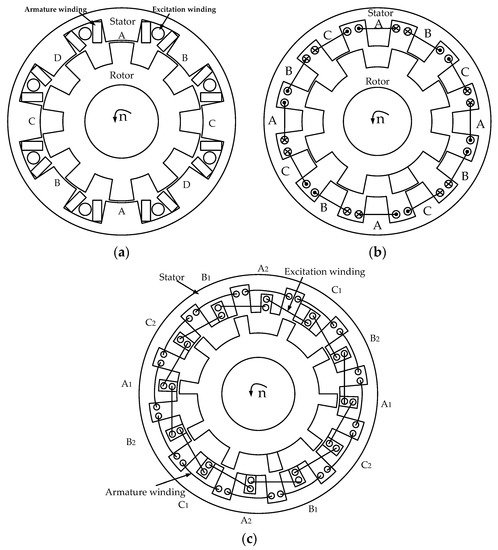
可变磁阻电机(VRM)有两种:单边凸极和双边凸极。双边凸极VRM由于其最大与最小磁阻之比最大和更好的机电能量转换特性等优点而更受欢迎。EEDSVRM 有 3 种类型,即绕场双凸极电机 (WFDSM) [ 3 ]、开关磁阻电机 (SRM) [ 4 ] 和电励磁磁通开关电机 (EEFSM) [ 5 ],如图1 .
近年来,EEDSVRM越来越受到关注,成为机器领域的研究热点之一。在[ 6,7,8,9,10,11,12 ],用于EEDSVRM控制策略的研究,提出了。传统的位置传感器具有许多固有的缺点,例如增加了驱动系统的成本和降低了机器的鲁棒性。为了提高 WFDSM 的整体稳定性,将采用机器自感与转子位置之间的关系来估计转子位置的无位置传感器控制策略应用于 WFDSM [ 6 , 7]。针对VRM固有的转矩脉动大的问题,提出了一种结合自适应终端滑模抑制SRM转矩脉动的瞬时转矩控制策略[ 8 , 9 ]。研究了一种改进的12/8极WFDSM驱动系统直接瞬时转矩控制方法。该控制策略的应用可以有效降低WFDSM的转矩脉动,提高转矩输出能力[ 10 ]。在 [ 11],针对功率变换器的故障,提出了一种新的容错控制策略。仿真结果表明,所提出的容错控制策略可以有效缓解因功率变换器故障引起的WFDSM输出性能下降。在[ 12 ]中,滑模控制被应用于磁通开关机(FSM),可以提高FSM驱动系统的稳定性。在 [ 13],研究了EEFSM的短路和开路故障的故障特性。通过改变功率晶体管的开关状态,可以实现基于速度、绕组、电流和短路电流的基本三闭环容错控制策略。为SRM[ 14 ]引入了一种基于小波包分解的故障诊断方法。WFDSM 的功率变换器故障诊断在[ 15 ]中提出。该控制策略在VRM中被广泛使用,因为它抑制了转矩脉动,使转矩更平滑,提高了VRM的整体鲁棒性。
As a new electric excitation machine, EEDSVRM is widely used in popular fields such as aerospace and electric vehicles because of its simple structure and high robustness. However, due to its structural characteristics, VRM has problems such as excessive torque pulsation, which affects operating performance. Therefore, it is necessary to consider the machine structure and optimize the design of the machine to find the optimal combination of structural parameters to make the EEDSVRM achieve the best operating performance, which is of great benefit to the large-scale application of VRM in industry. The optimization design of EEDSVRM ontology was researched in [16,17,18,19,20,21]. There are many types of EEDSVRM ontology optimization designs, which can be roughly divided into five types: novel machine topology-based optimization, finite element simulation-based optimization, mathematical analysis-based optimization, intelligent algorithm-based optimization, and multiple fusion-based optimization. These five optimization design methods have their own characteristics. It is relatively time-consuming to propose new machine topology optimization and finite element optimization. Although mathematical formula analysis meets the requirements of real-time optimization, the optimization accuracy is still insufficient compared to finite element. Multi-objective optimization using intelligent algorithms can improve optimization efficiency. The optimization method of multiple fusion combines the advantages of multiple optimization methods and greatly improves the optimization efficiency as well as reduces the optimization cost.
2. Basic Topologies, Principles, and Performances
2.1. WFDSM
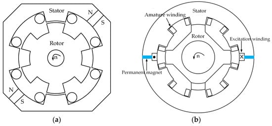
According to the machine excitation mode, the Doubly Salient Machine (DSM) can be divided into three categories, as follows: the Wound-field Doubly Salient Machine (WFDSM), which is shown in Figure 1a; the Doubly Salient Permanent Magnet Machine (DSPM); and the Hybrid Excitation Doubly Salient Machine (HEDSM), as shown in Figure 2 [22,23,24]. Compared with DSPM and HEDSM, WFDSM does not use permanent magnets for excitation. Instead, it only relies on the DC power supply to provide the excitation source. In this way, the magnetic flux of the machine can be controlled by adjusting the amplitude of the excitation current and the risk of irreversible demagnetization of the machine can be avoided. Therefore, the WFDSM can be used in harsh environments and has a strong magnetic flux adjustment capability.
The working mode of WFDSM is different from DSPM and HEDSM, which adopt permanent magnet excitation because of the DC excitation mode. When current flows into the excitation winding, a magnetic field is established inside the machine. The magnetic flux generated by the main magnetic field passes through the yoke and magnetic poles of the stator and rotor and penetrates the entire magnetic circuit of the machine. When the machine rotor is driven to rotate by the prime mover, the flux linkage of the armature winding changes with the rotor position, resulting in a symmetrically induced potential. Unlike the permanent magnet excitation, the air gap magnetic field remains constant, which results in poor output voltage regulation and fault demagnetization capabilities. In WFDSM, the main magnetic flux of the machine can be controlled by adjusting the excitation current to affect the output voltage. The external uncontrollable rectifier circuit is shown in Figure 3 [25], where eAf, eBf, eCf, and eDf are the induced voltages of windings A, B, C, and D; WA, WB, WC, and WD are the windings A, B, C and D; RA, RB, RC, and RD are the self-resistance of the armature windings of A, B, C, and D; and R is the external load.
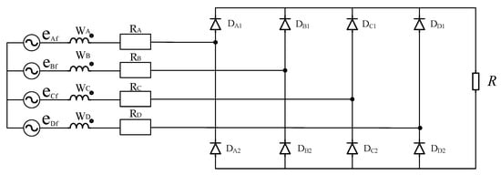
Figure 3. Full bridge rectifier circuit [25].
2.2. SRM
The stator and rotor of SRM are salient pole structures. As shown in Figure 1b, the salient pole of the stator is wound with armature winding, while there is no excitation winding. The magnetic flux moves along the path of minimum reluctance. When the stator and rotor poles are aligned, the air gap reluctance is the smallest. On the contrary, when the cogging is aligned, the air gap reluctance of the machine is the largest. Therefore, SRM follows the principle of minimum reluctance and the magnetic field is distorted to produce electromagnetic torque. Due to its simple structure, stable operation, and wide speed regulation range, it is widely used in aerospace, electric vehicle, and other fields. SRM have two-phase, three-phase, and multi-phase structures, and the stator and rotor also have different pole slot matching combinations. Generally speaking, if the multi-phase structure is adopted, the torque ripple of SRM is relatively small [26]. The relationship between the pole slot and phase number of SRM is as follows:
(1)
where is the least common multiple of the number of poles of the stator and rotor, m is the phase number of SRM, and and represent the number of poles of the stator and rotor, respectively.
The pole slot between the stator and rotor of SRM is shown in Table 1. The most common one is the three-phase 12/8-pole machine, as shown in Figure 1b. Increasing the number of poles of SRM can reduce the torque ripple and vibration problems caused by SRM to a certain extent [27].
Table 1. Common pole slot fit combination of the stator and rotor of SRM.

2.3. EEFSM
Identical to the excitation method of DSM, in addition to EEFSM that uses only direct current for excitation, FSM also includes a flux-switching permanent magnet machine (FSPM) that uses permanent magnets for excitation and a hybrid flux-switching machine (HEFSM) in which permanent magnets and direct current are used for excitation at the same time. The topology of FSPM and HEFSM are shown in Figure 4. Although FSPM is considered to be the latest stator excited reluctance machine [28],用于励磁的永磁体不可避免地会遇到退磁问题。正是由于能够在高温和恶劣的工作环境下实现磁场调节和故障退磁,EEFSM越来越受到关注,成为VRM领域的研究亮点之一。图1c 显示了 EEFSM 使用最广泛的 12/10 极。
如在所示图1中C,可以看出,存在于定子12的凸极硅钢芯。在定子齿上开槽,励磁绕组嵌入其中。相邻两组定子槽的励磁电流是相反的。
与传统的SRM相比,EEFSM可以全周期工作,扭矩密度和功率密度都更高,更适合航空航天、海上风电等高性能要求的应用。
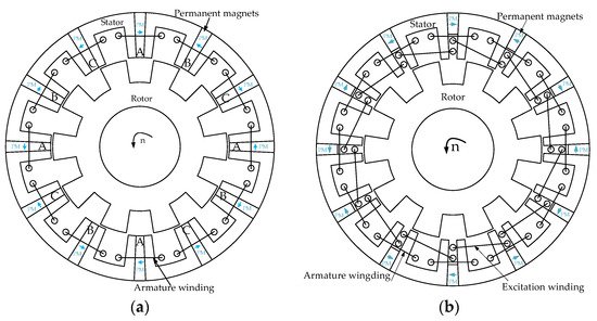
随着转子磁极与定子齿重叠面积的周期性变化,主磁路中的气隙导磁率也发生变化,导致相绕组中的磁联动和反电动势随转子位置而变化,从而实现了所谓的“磁通切换”,如图5所示。合理设计FSPM的极槽配合,优化整机结构尺寸,可使磁链和反电动势波形接近正弦波。
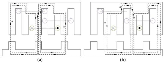
图 5. ( a ) 磁链的最大前向位置。( b ) 磁链的最大反向位置。
This entry is adapted from the peer-reviewed paper 10.3390/en15010228
This entry is offline, you can click here to edit this entry!