 +1 credit
| Version | Summary | Created by | Modification | Content Size | Created at | Operation |
|---|---|---|---|---|---|---|
| 1 | YuXiang Peng | + 3742 word(s) | 3742 | 2021-11-22 02:58:19 | | | |
| 2 | Vicky Zhou | Meta information modification | 3742 | 2021-11-22 09:52:40 | | | | |
| 3 | Vicky Zhou | -257 word(s) | 3485 | 2021-11-25 08:22:54 | | | | |
| 4 | Vicky Zhou | -2177 word(s) | 1308 | 2022-04-13 11:08:22 | | | | |
| 5 | Vicky Zhou | Meta information modification | 1308 | 2022-04-13 11:08:43 | | |
Video Upload Options
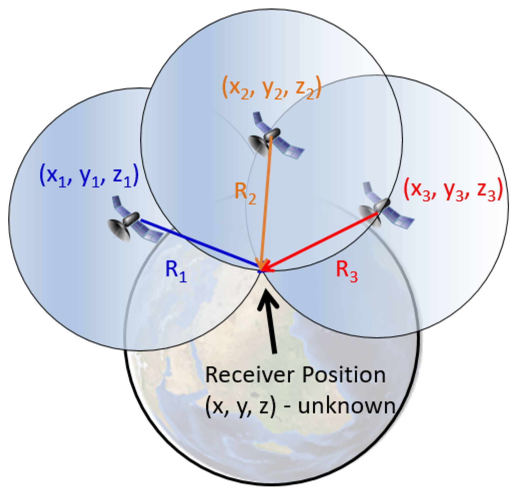
The Global Navigation Satellite System (GNSS) plays a pivotal role in our modern positioning, navigation and timing (PNT) technologies. GNSS satellites fly at altitudes of approximately 20,000 km or higher. This altitude is above an ionized layer of the Earth’s upper atmosphere, the so called “ionosphere”. Before reaching a typical GNSS receiver on the ground, GNSS satellite signals penetrate through the Earth’s ionosphere. The ionosphere is a plasma medium consisting of free charged particles that can slow down, attenuate, refract, or scatter the GNSS signals. Ionospheric density structures (also known as irregularities) can cause GNSS signal scintillations (phase and intensity fluctuations). These ionospheric impacts on GNSS signals can be utilized to observe and study physical processes in the ionosphere and is referred to ionospheric remote sensing. This entry introduces some fundamentals of ionospheric remote sensing using GNSS.


| GPS | GLONASS | Galileo | Beidou | |
|---|---|---|---|---|
| Affiliation | U.S.A. | Russia | European Union | P.R. China |
| Orbital Altitude |
MEO (∼20,200 km) |
MEO (∼19,100 km) | MEO (∼23,222 km) |
MEO/GEO/IGSO |
| Number of Operational Satellites (Scheduled total) |
31 (32) | 23 (29) | 22 (30) | 56 (≥61) |
| Signal and Frequency (in MHz) |
L1 (1575.42), L2 (1227.6), L5 (1176.45) |
G1 (1602 + n × 0.5625), G2 (1246 + n × 0.4375), G3 (1201 + n × 0.4375) * |
L1 (1575.42), E5 (1191.795), E5a (1176.45), E5b (1207.14), E6 (1278.75) |
B1 (1561.10/1575.42), B2 (1207.14/1176.45), B3 (1268.52) |
The GPS satellites are located within six different orbital planes of medium Earth orbit(MEO) with an altitude of ∼ 20,200 km. Each two neighboring orbital planes are separated by 60 degrees in Ω (longitude of the ascending node). The inclination angle of all GPS satellites is approximately 55 degrees. The orbital period of all GPS satellites is approximately 12 h. By design, a GPS receiver at any place on the Earth’s open surface should be able to track at least six line-of-sight (LOS) direction satellites. The GPS constellation is designed with a total number of 32 satellites in orbit. Currently among the 31 operational GPS satellites, 11 satellites broadcast the L1 (1575.42 MHz) signal only, 7 satellites broadcast the L1 and L2 (1227.6 MHz) signals, and 13 satellites broadcast the L1, L2 and L5 (1176.45 MHz) signals. The transmission of these GPS civilian radio-frequency (RF) signals is based on the Code Division Multiple Access (CDMA) spread-spectrum technology. The details of GPS signal structure can be found in the Interface Control Documents (ICD) [1]. The latest status of the GPS constellation can be found at the U.S. Coast Guard Navigation Center website [2].
Currently, 24 operational GLONASS satellites are located within three different MEO orbital planes with an altitude of ∼19,100 km, which indicates GLONASS satellites’ orbital period is ∼11 h 15 min. Each two neighboring GLONASS orbital planes are separated by an Ω of 120 degrees, and all satellite inclination angles are approximately 64.8 degrees. In contrast to the GPS constellation, the transmission of GLONASS civilian RF signals is based on the frequency division multiple access (FDMA) technique. Therefore, the RF transmitting frequencies under the same frequency band on different GLONASS satellites are different. 22 out of the 24 GLONASS satellites transmit dual frequency bands, where their G1 center frequency is 1602 + n × 0.5625 MHz and G2 center frequency is 1246 + n × 0.4375 MHz (where n is the satellite frequency channel number). The other two GLONASS satellites transmit an additional frequency band, G3, with a center frequency of 1201 + n × 0.4375 MHz. The details of GLONASS signal structure can be found in their ICDs [3]. The latest status of the GLONASS constellation can be found at the Russian Information and Analysis Center for Positioning, Navigation and Timing website [4].
Currently, 22 operational Galileo satellites are located within three different MEO orbital planes with an altitude of ∼23,200 km, which gives an orbital period ∼14 h 7 min for the Galileo satellites. The FOC stage of Galileo is expected to be composed of 30 satellites in total. Each neighboring Galileo orbital plane is separated by an Ω of 120 degrees, and all satellite inclination angles are approximately 56 degrees. The Galileo constellation utilizes the CDMA technique for RF signal transmission. All the Galileo satellites broadcast E1 (1575.42 MHz), E5a (1176.45 MHz), E5b (1207.14 MHz) and E6 (1278.75 MHz) civilian signals. Galileo receivers may receive the E5 AltBOC modulation signal, a modified version of a Binary Offset Carrier (BOC) with a center frequecy of 1191.795 MHz. The details of Galileo signal structure can be found in their ICDs [5]. The latest status of the Galileo can be found at the European GNSS Service Centre website [6].
The orbits of the Beidou constellation are more complicated than the other three constellations. Out of the 43 currently operational Beidou satellites, 5 satellites are in the geostationary orbit (GEO) over the Asian sector; 10 satellites are in inclined geosynchronous orbits (IGSO) with an altitude of ∼35,786 km and an inclination angle of 55°; 28 satellites are in MEO with a nominal altitude of ∼21,528 km. The MEO satellites are separated within three orbital planes (equally divided by 120 degrees) with an orbital period of ∼12 h and 53 min. Compared to other GNSS constellations, the more complicated orbit geometry of the BDS can increase positioning accuracy by providing lower horizontal, vertical and temporal dilution of precision (DOP) particularly in a large portion of the eastern hemisphere region (60° S–60° N and 50° E–170° E) [7]. More BDS satellites will be launched to complete the full constellation with at least 49 satellites in total. Beidou second generation satellites transmit public RF signals in three different frequency bands: B1 (1561.098 MHz), B2 (1207.14 MHz) and B3 (1268.52 MHz). Beidou third generation satellites also transmit three different frequency bands of public signals: B1 (1575.42 MHz), B2 (1176.45 MHz) and B3 (1268.52 MHz). The details of BDS signal structure can be found in their ICDs [8]. The latest status of the Beidou constellation can be found at the Test and Assessment Research Center of China Satellite Navigation Office website [9].
References
- GPS Interface Control Documents. Available online: https://www.gps.gov/technical/icwg/#current (accessed on 11 October 2021).
- GPS Constellation Status (U.S. Coast Guard Navigation Center). Available online: https://www.navcen.uscg.gov/?Do=constellationstatus (accessed on 10 May 2021).
- GLONASS Interface Control Documents. Available online: https://www.glonass-iac.ru/en/documents/ (accessed on 11 October 2021).
- GLONASS Constellation Status (IAC; Information and Analysis Center for Positioning, Navigation and Timing). Available online: https://www.glonass-iac.ru/en/GLONASS/ (accessed on 10 May 2021).
- European GNSS Service Center Programme Reference Documents. Available online: https://www.gsc-europa.eu/electronic-library/programme-reference-documents (accessed on 11 October 2021).
- Galileo Constellation Information (European GNSS Service Centre). Available online: https://www.gsc-europa.eu/system-service-status/constellation-information (accessed on 10 May 2021).
- Wang, M.; Wang, J.; Dong, D.; Meng, L.; Chen, J.; Wang, A.; Cui, H. Performance of BDS-3: Satellite visibility and dilution of precision. GPS Solut. 2019, 23, 56.
- BeiDou Navigation Satellite System Interface Control Documents. Available online: http://en.beidou.gov.cn/SYSTEMS/ICD/ (accessed on 11 October 2021).
- BeiDou Constellation Status (CSNO-TARC; Test and Assessment Research Center of China Satellite Navigation Office). Available online: http://www.csno-tarc.cn/en/system/constellation (accessed on 10 May 2021).

