1. Floating Wind Turbines
A balance among the two varying principles (i.e., the requirement for a stable foundation for the wind turbine’s control and operation and the nature of the substructure being innate, to respond to environmental forces) is required for the design of the floating platform for wind energy
[1]. As explained in
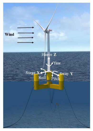
Figure 1, the absence of rigid foundations results in an additional six degrees of freedom (DOFs) for the platform of floating turbines; three translational (surge X, sway Y, and heave Z) and three rotational (roll RotX, pitch RotY, and yaw RotZ). For the platforms of onshore wind turbines and bottom-mounted offshore wind turbines, the effect of soil-structure interaction (SSI) can be modeled with six degrees of freedom; three translational (horizontal forces in X and Y and vertical force in Z) and three rotational (rocking moments in X and Y and a torsional moment in Z) respectively.
Figure 1. Six DOF for a floating platform; Reprint with permission
[2]; 2019, Naval Energies.
The soil–structure interactions have a positive effect on the structural vibrations of the system, as they add damping. The peak shear force and peak bending moment in the foundation are not affected by the SSI
[3].
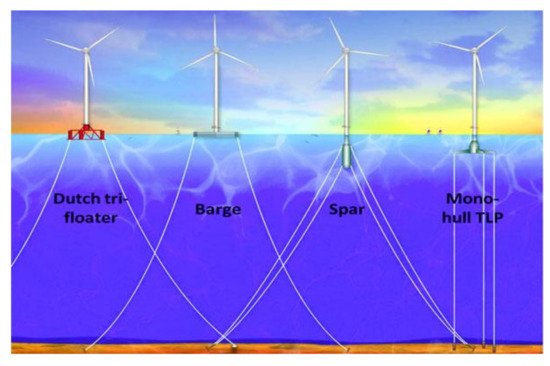
One of the challenges encountered due to the floating of wind turbines is that it is impossible to eliminate the motion that is caused due to wave and wind conditions. Thus, the turbine’s design should also consider the added DOF due to the platform’s movement. The four important concepts of the floating platform are as given in
Figure 2. In each concept, a different approach is used to achieve hydrostatic stability. These concepts include a semi-submersible platform (buoyancy and ballast stabilized Dutch tri-floater), a barge platform (buoyancy stabilized), a spar buoy platform (ballast stabilized), and a Mono-hull TLP (Tension Leg Platform stabilized by a mooring line)
[4][5].
Figure 2. Types of floating wind turbine platforms; Reprint with permission
[6]; 2007, NREL.
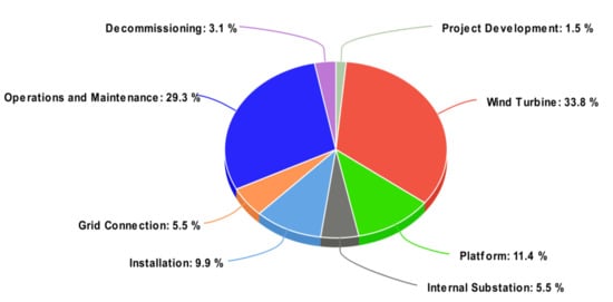
To achieve the lowest overall cost of the whole platform system for its entire life, it is necessary to optimize the floaters for wind turbines because as the depth increases, the construction cost of the wind farm increases due to the floating foundation
[7]. The breakup of the total cost of the system for a typical TLP type floating offshore wind turbine is shown in
Figure 3, which includes the costs of maintenance, decommissioning, and operations.
Figure 3. Cost Estimation for Offshore Wind Projects based on data from
[8].
Although weighing the significance of every element differently, the design of wind platforms will include the same issues governing the oil and gas platforms. To control pitch, heave motions, and support the turbine’s weight, the floating structure should provide enough buoyancy. Offset by high winds, the extra costs of the system of power distribution and the floating structure determines the economics of the wind turbines in deep water. As proved by the integrated cost models of energy, if the platform cost is managed near to 10% of the overall capital cost of the system, then the USD 0.05/kWh goal of the Department of Energy (DOE) cost is possible to attain
[1][8].
The historical development of distinct types of floating platforms is discussed as follows. With the use of catenary mooring lines and the spar-buoy concept, Tong
[9], created a 1.4 MW floating turbine in 1998. To assess the floater’s performance, an in-depth dynamic analysis was conducted, both for the performance of the mooring system and its design including the impact of unsteady and steady wind and wave loads. The statistics of dynamic mooring lines and motion response because of the low-frequency motion and high wave frequency were estimated. Tong observed that the main loads acting at the tower are wave loadings but were not severe, thus becoming the tower’s main design driver. In addition to this, the gyroscopic yaw motion which was caused due to the platform pitch resulted in being small and not causing any serious harm.
2. Previous Work on Single Wind Turbine Floating Platforms
Sophisticated and reliable tools are required for the manufacturing and design of cost-effective and optimized floating wind turbines that can generate the required response and dynamics properly and effectively
[10]. Due to the complexity in the coupling of hydrodynamics, aerodynamics, and structural dynamics, it is difficult to predict the characteristics of wind turbines. Calculating the loads is important to get exact and useful analysis outputs in the design phase of the offshore floating wind turbine.
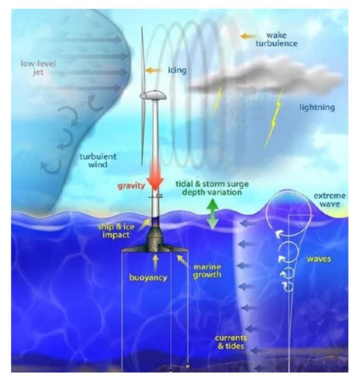
Figure 4 shows the various operating conditions of a floating wind turbine
[11][12].
Figure 4. Offshore floating wind turbine loading sources; Reprint with permission
[12]; 2007, NREL.
The operating conditions also include the aerodynamic damping (2–5%)
[13], initiated by the turbine rotor, the gyroscopic loads of the blades, the viscous resistance caused by the interactions of wave and body, and the hydrodynamic loads that resulted due to the excitation of waves
[14]. Due to the hydrodynamic effects, the rotors of offshore wind turbines are under platform-induced rotating motions. Non-linear aerodynamics and unsteadiness in operating turbines are induced by the coupled motion of the rotating rotor and platform pitching. This has a strong impact on the performance of the rotor, power generation, and thrust
[15].
A ship-mounted inclined-axis wind turbine was tested by Dumpleton
[16] in 1985, where the ship was on a swinging mooring with a single blade rotor. As compared to the ship’s main engine, the main mechanism of the turbine was placed in a protected condition in the hull. Due to there being no limitation on the size and weight of the plant, the likelihood of having better and reliable equipment increases. Various technical issues were emphasized in the test and a conceptual idea of using a ship-shaped hull with an arbitrary axis turbine was conceived.
To find out the effectiveness of semi-submersible wind turbines, a numerical and analytical design tool was introduced by Henderson and Patel
[17] in 1999. The key issues highlighted were finding out the best hull form for the structure of the floating turbine and creating tools for the analysis required for the motion of waves and their interaction with the platform and also the performance of the aerodynamic system. An advantage was that the vessel’s main structure was placed below the surface of the ocean; this was a benefit over the traditional structures including hull forms that are near to the surface of the water. The characterization of the motion response to the waves was done by the pontoon structure, bracing yields and columns, and the submergence of the pontoon. However, huge submersible structures are needed to float wind farms with greater displacements and deep drafts.
In the year 2004, fully coupled time-domain simulations were carried out by Withee
[18], for obtaining the system response for a wind turbine (1.5 MW) under the wave and wind loading and installed on top of the TLP floater. They included the aerodynamics loading on the wind turbine and the non-linear loading on the sub-merged floater. To support the balance of the wind turbine, a tension leg spar buoy was used; the idea of choosing this was due to the small size of the platform, and therefore, the low cost per wind turbine. At the end of the spokes, the tethers of the system were attached that radiated outward from the spar cylinder. This arrangement of the spokes and the lines under tension is ensured to be very rigid in the pitch and roll modes of motion. Additionally, the simulation results were presented which were done to find out the presence of damping which might be due to the turbine’s rotor, and they noted that the damping factor was following a distinct linear law. The quadratic damping coefficient in the surge (0.048) and sway (0.045) due to the viscous drag had comparable values. They also found the bending moments of the rotor blade at the root and the typical system responses for specific wind speeds.
An analysis of the frequency domain response was carried out by Lee K.H
[19], in 2004, on both Spar Buoy and TLP forms of floating wind turbines to compare the performance of the two concepts of the floater. From the solution of the complex eigenvalue problem found from equations of motion, the natural frequencies were estimated by setting the moments and exciting forces to zero and also neglecting the effect of linear damping. Approximation of the added mass matrix is done by its zero-frequency value. It was observed that the tension leg platform was generally flexible in sway and surge yet rigid to a great degree in the roll, pitch, and yaw modes, while the spar platform was observed to be rigid in sway and surge however flexible in the roll, pitch, and yaw modes.
For analyzing the spar-type turbine integrated dynamics, Skaare et al.
[20] proposed a simulation model. They proposed a model similar to the Hywind, and the numerical data were then compared with the existing scaled model test outcomes. Control schemes for the wind turbine and various other environmental conditions were also considered. The platforms were designed in such a way that the modes of motions exciting from the waves have natural periods far from the range of wave frequency values. Similarly, considering the pitch restoring force, the static tilt was small as predicted. The impact and significance of the control by blade pitch angle of the wind turbine on its dynamic response for working with winds higher than the usual wind speed were shown. This proves that, for the reason of proper analysis of dynamic response, the modeling of hydro-servo-aero dynamic coupling is needed. The modeling includes the hydrodynamic model, aerodynamic rotor model, environmental conditions, and the control system. The main issue is combining the wind and wave load models and the selection of the control strategy for the blade pitch angle.
Investigations were done by Suzuki and Sato
[21], in the year 2007, to see the impact of a stabilizing fin for decreasing the pitch motion of the wind floater when the fin is placed at the bottom of the support of the spar type floater. This idea closely resembles bilge keels and roll stabilization fins attached to the ship vessels. The rotational movement caused by an uneven load from the wind on the floater can be dampened about the perpendicular axis by using the above-mentioned setup, since a fin gives extra hydrodynamic mass.
A combined hydro-aero-servo-elastic analysis was presented by Jonkman and Buhl
[6] for the load analysis of the 5 MW pontoon type turbine. The main motive was to find the various forces and their dynamic reactions that would be averse to a pontoon-type platform. In the model, other things that were included are sea currents, a non-linear viscous draft from the wave kinematics, platform motion, linear hydrostatic restoring, the additional damping and mass contributions from the linear radiation of waves, which included the excitation of incident waves from linear diffraction in irregular and regular sea and the impact of free surface memory. Similarly, as aerodynamic loads rely upon the state of the airfoils of the rotor blades, the hydrodynamic loads rely upon the geometry of the support platform. It was emphasized that when the response of the turbine and pitch motion of the pontoon are combined, it created greater reactions in the wind turbine blades and tower. When the wave conditions were critical the barge was sensitive for added pitching of the platform. Some alterations were proposed to minimize the boat movements.
Matsukuma and Utsunomiya
[22] performed research in 2008, in which they analyzed the movement of the spar-type floater, with rotor rotation in the presence of steady wind. Using the blade momentum concept, the evaluation of the blade forces due to wind was done. The outcome of this was the production of yaw, sway, and roll motions because of the gyro-moment effect. This research was continued and the motion of the turbine was further analyzed with the use of normal and abnormal waves along with a parallel load that gave rise to the smooth flow of the wind
[23]. The turbine was a 2 MW, with a diameter of 80 m and a height of 55 m. At the National Marine Research Institute, a few experiments had taken place with the use of the scaled model as well as on the stepped type floating cylinder, which showed a smaller heave and pitch movement when moored at an upper place in comparison to the uniform cylinder counterpart
[24]. Another sea experiment was performed by Utsunomiya and the team, using another reduced model of a composite spar turbine
[25]. The results were obtained for the six-degree motion of the tower base. The outcome thus confirmed the numerical methods as well as the computer codes used in the spar-type floating turbine analysis in the presence of various forces of wave and wind.
Furthermore, an analysis was performed by Sclavounos
[26], which demonstrated a review of the turbine and the anchorage system along with all of its parameters. Different parameters including the nacelle acceleration, tension, and displacement were demonstrated that were favorable to the 5 MW wind turbine. The selection of all concepts was done carefully for the safe towing of the floater to the installation site and attaching it with the anchorage system. A large space was allocated for the concrete ballasted cylinder. The geometry of the platform was characterized by the barge draft and radius. Eight similar tethers were included in every mooring system which was divided into two groups and spaced 90 degrees apart. Four mooring line groups were included in the structure instead of having three for the system to become stable in a case when one section fails to perform. Coupled dynamics of the floater along with the mooring cables were done using the existing simulation tools that are used by the offshore wind industries. It was observed that the feasible designs are shallow drafted barge ballasted or narrow deep drafted spar. The catenary and tension leg were both included in the mooring system.
Different cases were demonstrated by Suzuki et al.
[27], regarding progressive drifting of the turbines in the wind farm, which was closely spaced, thus lowering the costs of installation. Collisions of turbines would result if the floating turbine drifts accidentally. Cases like these were discussed and the risks were identified about the arrangements of turbines to contribute to the safety in this matter.
Furthermore, a life cycle assessment was performed by Weinzettel
[28] for the offshore floating type turbine using the concept of Sway TLP. This assessment emphasized the effects of the environment by putting forward the significance of recycling after decommissioning the wind turbine to minimize the detrimental effects on the environment. The outcomes of this assessment were compared with the processes of the Ecoinvent database for the production of electricity by the natural gas power plant and wind power plant. Secondary materials had not been included in this; however, they included the recycling of metals for avoiding the production of materials. Their structural design had the submerged tower under the sea where the upper portion of the submerged part was stuffed with air to aid the floating of the turbine and olivine ballast was filled at the bottom part which aided in balancing the wind turbine. The wind turbine was attached to the mooring part developed from stones at the bottom of the sea with the help of the torsion leg.
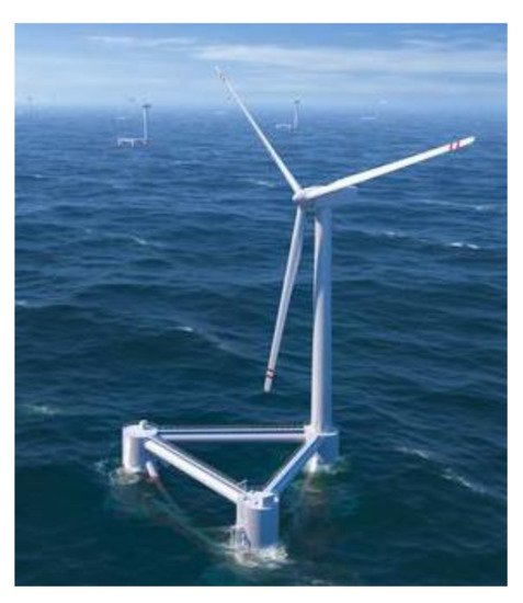
A study, regarding the wind float foundation, was conducted by Cermelli et al.
[29][30][31][32] in three parts, the structure of this foundation is shown in
Figure 5. The wind float consists of a three-legged foundation for huge offshore turbines. This design aids the accommodation of a 5 MW or greater turbine enabling fewer changes to the nacelle, turbine, and tower.
Figure 5. Semi-submersible floating wind turbine; Reprint with permission
[29]; 2019, Principle Power.
3. Previous Work on Multi-Wind-Turbine Floating Platforms
In 2003, various options for platform design were considered by Henderson et al.
[33][34], which comprises the multiple or single turbines per floating platform, and multiple or single rotor turbines. It was initially concluded, with the help of qualitative analysis, that the best economic and technical solution was a single turbine per floater including a spread mooring. In 2004, a confirmation was made by Musial et al.
[35] on this discussion. The advantages and disadvantages of both concepts were laid out. The advantages of multi-wind-turbine platforms over single wind turbine platforms include wave stability, common anchors, fewer transmission costs, and the possibility of mass optimization. The disadvantage is that the yaw control for the multi-turbine platform is complex and the support structure is relatively expensive. However, the analysis done was not complete and many issues were to be considered, including:
- ➢ The requirement for the evaluation of barge platforms
- ➢ Heave and roll were explained by simple equations of motion
- ➢ The analysis did not explain the impact of waves and mooring lines
In 2006, a model based on the Fourier spectrum was applied by Zambrano et al.
[36] to a 6 DOF moored type floating platform with 3 turbines installed on it. A fourth-order Newtonian Runge–Kutta approach was used to find the resulting sway, surge, and heave motions. The wave, wind, and anchorage cable tension forces were determined by varying the time. To create the wave forces on the platform, the Wave Analysis Massachusetts Institute of Technology (WAMIT) program was used. Additionally, to predict the wind turbine loads, a constant force coefficient was used.
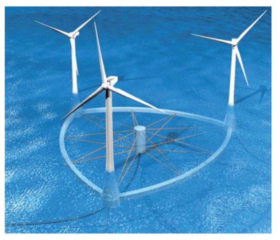
The semi-submersible floating platform’s dynamic response was studied by Ishihara et al.
[37] and Shimada et al.
[38], as shown in
Figure 6. The characteristics of the waves causing these motions were presented in their research. In addition, 1:150 reduced model examinations were conducted in a water container with external wave excitations. In the equation of motion and the computations, the impact of nonlinear damping because of inertia forces and fluid dynamic viscous loads (using the formula of Morison) were considered. Here, Green’s function model was used to obtain linear hydrodynamic forces. As an outcome, improvements were observed in the characteristics involved in the resonant frequency region. Additionally, the investigation was also done on the long-term fatigue limit and the stability of the structure in conditions of severe waves.
Figure 6. Semi-submersible offshore floating wind turbine; Reprint with permission
[37]; 2007, ICWE12 Cairns.
The development of the design of mobile, as well as a large structure with many wind turbines for offshore sailing type wind farms, was explained by Manabe et al.
[39]. Through this study, an analysis was done on the concept of a floating wind farm adding authenticity to the realization of the concept. Considering the coupled hydro-elastic analysis, the sailing wind farm’s design was presented in this paper. In any case, the outline technique was not the same as that utilized in common structures of marine. To approximate the interactive forces between fluid and structure appropriately, a hydro-elastic analysis was important. Accurate analysis of fatigue strength was important because the offshore wind farm used the light structure rather than the common marine structure. The hydro-elastic analysis forms the basis for the design of the structures for these large offshore wind turbines, which was evident from the efforts of Japanese researchers in tapping on large mobile offshore structures to realize the importance of floating wind farms.
Resistance and towing tank tests were carried out by Kourogi
[40][41] and the team with the use of a scaled model of sailing type floating wind turbine structure to enhance the simulation of navigation and also examine the interactions between the struts and semi-submersible hull. To reduce the drag of the wind force, a lift force was introduced with the aid of vertical struts on the lower hulls. To increase the energy profitable ratio (ratio between output and input energies), it was essential to create the best route to generate the maximum energy. Hence, taking into consideration the stormy weather as well as the wind power extent, they planned to build a most favorable route. The rate of wind power was set to a maximum of 40%, i.e., greater than the capacity factor. Apart from this, the wave height was set to a maximum of 6 m, above which the structure was bound to evacuate. Examinations and tests were also carried out for analyzing the performance of seakeeping. There were many dissimilarities between this design concept and that of the conventional offshore designs.
In 2011, Lefranc and Torud
[42] performed feasibility, design, and cost analysis for a semi-submersible floating platform with three turbines on it. To increase the distance between the tower and rotor blades, the towers were inclined. A scaled model of 1:150 was used in experiments to investigate the wake interactions between the turbines. Wind tunnel tests were done with a turbulence intensity of 9% to replicate the offshore wind conditions and a wave basin was used to test the interaction of the platform with regular and irregular waves. It was shown that the wake interaction between upwind and downwind turbines was the most challenging issue and proved that the power loss due to the wake effect at low velocities was significant, while at high velocities it was almost unchanged. The economic analysis proved that the multi-wind-turbine concept was comparable to the current single platforms in terms of the cost of energy production.
Hu et al.
[43] used a numerical model, experiment, and Computational Fluid Dynamics (CFD) simulation for the hydrodynamic analysis of a semi-submersible floating multi-wind-turbine platform. The experiment without consideration of wind on a 1:50 scaled model was carried out to check the accuracy of the two numerical models in predicting the wave-–body interaction between the waves and platform. The potential flow method was used in the numerical model to analyze the linear wave–body interactions. The CFD model was used to calculate the pressure distributions on the platform due to waves.
A fully coupled analysis was developed by Bae and team
[44] that involved various turbines on a separate floating platform including mooring lines, by expanding and combining different tools of computer-aided engineering. A global combine matrix that includes all the degrees of freedom and coupling forces that are relevant solved the equation of motion for the system with various turbines on a single floating platform. As an outcome, the full coupling between the blades, towers, floater, drive-trains, and mooring framework, the dynamics of the MUFOWT (multiple units floating offshore wind turbine) was obtained in a single run. However, the wake effects of the wind turbines were not considered in this study.
Kim et al.
[45] designed a control algorithm for a large semi-submersible platform with four turbines installed at each corner of the platform. ANSYS AQWA was used to obtain the hydrodynamic forces data and was implemented in GL-DNV Bladed. The gain scheduled pitch control and basic torque control with tower damper were used to reduce the tower in-plane and out-of-plane bending moments. However, the generated power standard deviation was significantly increased as a trade-off.
A square semi-submersible type MUFOWT has been recently studied and designed by South Korea which includes the installation of 3 MW wind turbines at the four corners
[46][47]. In addition to placing six energy converters at each side, the twenty-four-point power absorber type linear generator-based wave energy converters (WEC) were set up. In comparison to the conventional floating platform, the submerged platform has a unique size that showed distinct dynamic characteristics in the overall performance. A series of model tests were performed by the research institute in Korea on the MUFOWT with a Froude scale of 1:50
[48]. The model tests excluded the dynamic motions of wave energy converters which were fixed to the platform.
A numerical investigation on a hybrid wind–wave floating offshore platform was done by Lee et al.
[49] to analyze the multi-body hydrodynamic interactions in a frequency domain. The platform is semi-submersible with four 3 MW turbines at four corners and 24 wave energy converters on the sides. Jang et al.
[50] evaluated the effect of heave plates on the behavior of a multi-unit offshore floating wind turbine using a time-domain coupled dynamic analysis. Scaled model experiments were conducted to compare the numerical simulation. They showed that the heave plates with a minimal increase of mass can reduce the pitch and heave motions and also shift their natural frequencies.
In
[51], the hydrostatic stability analysis was performed on an OFMWTP (offshore floating multi-wind-turbine platform) configuration that was modeled based on the wake effect analysis. The platform configuration hosts five 8 MW wind turbines which were proposed for installing on the gulf coast of the United States
[52]. They also carried out an aero-hydrodynamic analysis to study the dynamic behavior of the OFMWTP operating in coupled wind–wave conditions. They also showed that the wake effect analysis carried out in the initial stages of design greatly reduced the power deficit at the downstream wind turbines
[53][54].
With the advent of high computing facilities, extensive numerical simulation of the multi-wind-turbine floating platforms is possible which can enable the development of better support structures for the platforms. The dynamics of the multi-wind-turbine floating platform is an extension of the single platform dynamics with additional degrees of freedom arising due to additional wind turbines. The advantages and disadvantages of single and multi-wind-turbine floating platforms are summarized in Table 1.
Table 1. Comparison of single and multiple wind turbine floating platforms.
| |
Advantages |
Disadvantages |
| Single wind turbine floating platform |
- ➢
-
Low requirements regarding the structure
- ➢
-
Standard control options for yaw
|
- ➢
-
Individual cost for anchors
- ➢
-
Less stable
- ➢
-
Low possibility of mass optimization
- ➢
-
Relatively higher transmission costs
|
| Multi-Wind-Turbine floating platform |
- ➢
-
Stability due to wave loads
- ➢
-
Common anchors
- ➢
-
Possibility of mass optimization
- ➢
-
Fewer transmission costs
|
- ➢
-
Support structure is relatively expensive
- ➢
-
Yaw control is complex
|
 +1 credit