 +1 credit
| Version | Summary | Created by | Modification | Content Size | Created at | Operation |
|---|---|---|---|---|---|---|
| 1 | Yerai Moreno | + 3298 word(s) | 3298 | 2021-07-13 12:33:46 | | | |
| 2 | Ron Wang | Meta information modification | 3298 | 2021-07-16 10:00:07 | | |
Video Upload Options
To increase the efficency of electric drives, the working frequencies are getting higher, bringing serious Electromagnetic Compatibility (EMC) problems, as well as insulation stress and higher bearing currents. Hence, it is important to have an electrical machine electrical equivalent circuit model to predict the electromagnetic interference levels. This review summarizes the current state of the art in electrical machine modeling and analysis in high frequency. The main analysis tools as Finite Element Methods, analytic and measurement-based tools are compared. Then, different machine high-frequency models are reported, detailing their individual features. Additionally, the influence of the machine design parameters in EMC behavior is outlined for future analysis. This is a short version of the full article.
1. Introduction
Typically, an electrical drive consists of a power source, an inverter that applies the desired voltage and frequency to the electrical machine, usually with Pulse Width Modulation (PWM) technique and the electrical motor, as shown in Figure 1. The straight arrows indicate the radiated noise caused by the switching circuits of the converter.
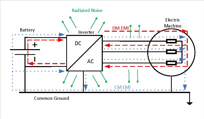
The dashed line represents the differential-mode EMI, which is going through one phase and returns across the other phases to the DC bus of the power source. Finally, the dotted line is the common-mode EMI, which goes across the common ground, connecting all elements to the disturbance [1].
Even if PWM technique is the most used control technique, its pulses generate a Common-mode voltage (CMV) in the output connection to the motor causing diverse problems such as leakage current, shaft voltage and bearing currents. The rapid voltage changes (high du/dt) also deteriorate the winding insulation and can cause protection failures in the case of short-circuit or contact defects [2][3][4]. Moreover, the generated EMI can affect the power source grid and the elements connected to it, for instance, sensors and safety systems in electric cars [5].
Specifically, bearings are affected by the CMV variations, as leakage currents flow through them [6][7]. Those currents damage the bearings, and together with the winding insulation damage due to voltage stress, the reliability and lifetime of the complete electric drive are decreased.
Some solutions are proposed to mitigate this EMI in electric drives. Different inverter typologies and modulation algorithms are proposed to reduce CM voltage [1][6][8]. Filters and other types of add-ons, such as shields or insulation are also widely used to avoid EMI flowing to the power grid as shown in [6][9][10][11], but they increase the cost of the drive, as well as the volume and the weight as they are bulky and heavy. Hence, those factors can reduce considerably the competitiveness of the final product on the market, for example, in the electric car.
Thus, to reduce the development cost of the product, an EMI strategy-based design should be added early in the product development cycle to reduce costs and achieve the best solution. Consequently, understanding and predicting EMI noise using high-frequency models during the design stage is essential to manage EMI problems.
According to the literature, the most extended modeling techniques for representing the behavior of electrical machines in high-frequency are based on electrical equivalent circuits or Lumped Parameter Models (LPM). These models consist of electrical circuits that comprise several resistances, inductances, and capacitances. For example, to analyze the influence of the winding placement and the winding connection on the bearing currents [12][13], to analyze the common-mode currents [14] or to analyze the over-voltages at motor terminals due to modulated supplying voltages [15]. Therefore, it is identified a lack of a comprehensive review about the analysis tools and methodologies for the study of electrical motors in high frequency, identifying the advantages and drawbacks of the main proposals that can be found in the literature.
As stated before, the final objective is an EMI reduction strategy-based design for electrical machines. To reach that objective, in this paper a comprehensive review of high-frequency behavior of electrical motors is proposed, covering the high-frequency phenomena, the tools available to analyze them accurately and the different existing high-frequency models. Thus, a review of the influence of different design parameters on the high-frequency behavior of the electrical machine is also collected in this paper. It is also found that the most influential design parameter is the winding placement and the impregnation amount, at least for CM currents.
2. High-Frequency Phenomena in Electrical Machines
In low-frequency operation range the parameters such as resistance and inductance hardly depend on the frequency, so they can be considered to be constants. However, in high frequencies, some new phenomena arise leading to variations in these parameters. Thus, as the frequency increases, the resistance increases and the inductance decreases.
Before analyzing any electromagnetic device in high-frequency, a specific frequency range must be defined depending on the application standards, as shown in this International Special Committee on Radio Interference (CISPR) guideline [16]. EMI conducted standards cover the frequency range from 150 kHz to 30 MHz, whereas the radiated standards cover the frequency range of 30 MHz to 100 MHz. However, in most cases, it is difficult to obtain models to achieve good accuracy in the whole range of frequencies, especially beyond 10 MHz [17][18][19][20][21]. Moreover, in [22], it is stated that the model of a transformer is not accurate beyond 10 MHz due to the current coupling between Differential-mode (DM) and Common-mode (CM) paths.
There are 4 main phenomena that must betaken into account when modelling electric machines in high frequency:
- Skin Effect: The skin effect is the first phenomenon that arises as the frequency increases. These Eddy currents cause a non-uniform current density inside the conductor, as the electrons are pushed to the outer region of the conductor. This way, the effective cross-section of the conductor is reduced with the frequency, as the current flows only in the skin depth of the conductor (see Figure 2). According to Equation (1), it can be deduced that the higher the frequency is, the thinner the skin depth is.
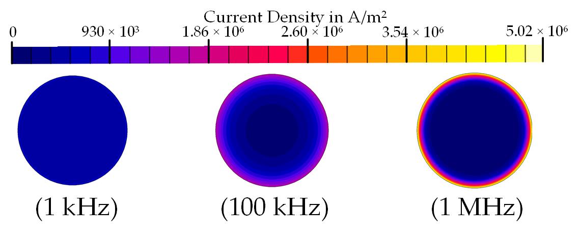
This surface distribution of the current increases the resistance and decreases the inductance due to the flux distribution inside the conductor. The skin effect is a local effect in each conductor, independent from the neighboring ones, so it can be analyzed simplifying the problem to a single conductor [23][24]. As it depends on the frequency and geometry, it can be mitigated using a smaller conductor diameter than the skin depth.
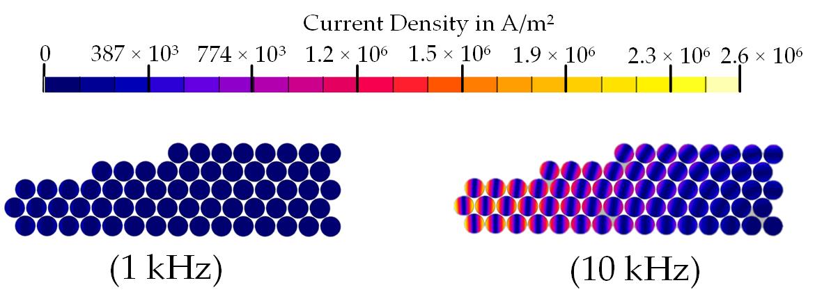
- Proximity effect: The neighboring effect between the conductors comprising a coil is defined as the proximity effect, and it is far more influential than the skin effect [25]. The basis is similar to the skin effect, but it considers the effect of induced Eddy currents in a conductor due to the high-frequency magnetic field created by the neighboring conductors. Thus, this phenomenon depends on the relative position between conductors and can be mitigated using windings with parallel strands or Litz wires, although they are complex to manufacture and they can generate unbalanced current distribution across the strands [26]. The distortion caused by this effect in the current density distribution of an electrical machine coil is shown in Figure 3.
- Magnetic Core: Regarding the magnetic core of electrical machines, in this region also demonstrates some high-frequency phenomena that might have a significant influence on the motor behavior. Generally, the stator and the rotor magnetic cores are laminated and made of electrical steel sheets to limit the Eddy currents induced by alternating magnetic fields, reducing the magnetic losses. The induced Eddy currents creates a shielding effect inside the electrical sheets that push the magnetic flux out of the iron core, leading to a decrease in the relative permeability of the magnetic material, and so in the value of the inductance [25][27][28]. The threshold frequency of this transition depends on the thickness of each steel sheet and its resistivity [29][30][27].
In the case of the laminated iron core, the inductance decreases less than in the bulk core since the magnetic flux is not completely pushed out of the laminated core. On the other hand, the resistance increases more in the laminated core, as the surface area where Eddy current flows is larger and the proximity effect between sheets increases the eddy currents in the core. It should be noted that the non-linearity of the magnetic saturation of iron core is neglected for those simulations, as well as the displacement current term, which is negligible at least below 1 GHz [30].
- Parasitic Capacitances: At low frequency, the influence of parasitic capacitances is negligible as their impedance is commonly large. Nevertheless, as the working frequency increases, the impedance of parasitic capacitances gets lower, leading to new current flow paths inside the motor. This might affect considerably to the differential and common-mode impedances, and so to the differential and common-mode currents in the motor [19][27][14][31].
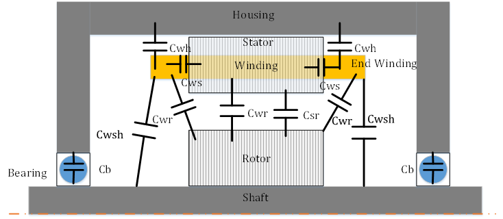
The main parasitic capacitances involved in an electrical motor are shown in Figure 4. Cwr is the winding-to-rotor capacitance, Cb is the bearing capacitance,Cws is the winding-to-stator capacitance, Csr is the stator-to-rotor capacitance,Cwh is the winding-to-housing capacitance and Cwsh is the winding-to-shaft capacitance.
In the winding, different capacitances appear. The inter-turn capacitance and the capacitance between phases that can be neglected if there is a single layer winding in the slot [27]. The complete common-mode (CM) paths are identified in [14]. To calculate the inter-turn capacitances, it is essential to consider the geometry, material and positions of the conductors inside the slot, as well as the thickness and the material of the insulation [32][33].
3. Analysis Tools
There are two different ways to analyze an electrical machine in high frequency. The first way is to determine the value of the Lumped Parameter Model (LPM) parameters of the motor by experimental measurements. This method is fairly the most used in the literature [12–36]. It is a practical method that achieves accurate EMC simulation of motor drives. Nevertheless, the manufactured motor is necessary for the measurements, so it is not valid for the design stage before prototyping.
In the second way, an equivalent circuit model or LPM is made so that each circuit constant is calculated with the design parameters of the motor either analytically [11,37–50], by Finite Element Method (FEM) [28,39,51–70] or even with hybrid methods [71–73]. With FEM-based electromagnetic field analysis, the inductance, resistance and capacitance of each turn of winding can be obtained, which are difficult to measure experimentally [55].
3.1. Finite Element Methods (FEM)
Regarding the FEM analysis, the detailed geometry of an electric machine can be accurately modeled obtaining precise resistance and inductance values, taking into account the skin and proximity effects, as well as eddy current losses in the stator and the capacitive couplings. The mesh of the geometry is essential to obtain accurate results in FEM. When working in high frequency, the skin depth of the materials must be finely meshed, both in the conductors to consider skin and proximity effects, and in the core, as the Eddy currents flow along the skin depth of the iron sheets. Thus, the mesh size must be thinner than the skin depth. However, this meshing requirement leads to a higher time consumption and computational load. Thus, an equilibrium must be found between the model complexity and the accuracy. For the active length of the machine, 2-D simulations are usually used, even if the resistivity of the sheets must be calibrated to take into account the lamination effects, usually using 3-D models. It must be remarked that not all iron sheets comprising the magnetic core can be modeled in 3-D with a mesh size thinner than the skin depth, otherwise, the model will take ages to solve. Commonly, 2 or 3 sheets are simulated and the results are extrapolated to the whole length. Even if the 3-D FEM is the most complete simulation tool, it is the most computationally demanding too, so it is usually only used for the end-winding calculation, as it is the only way to calculate it accurately. Once a 3-D FEM simulation is done, some authors propose different coefficients to take into account this end winding, by using just 2-D FEM for successive simulations. With respect to the capacitance calculation in electrostatic FEM, the same applied to magnetic calculation is applied, needing 3-D models for the end winding, at least for the winding- to-rotor capacitance calculation, where it has a big impact. In this case, a 2 mesh layer must be defined between the conductors for turn-to-turn capacitance accuracy. Gauss Law method is recommended for the calculation of the capacitance matrix, as it requires fewer simulations.
3.2. Analytical Methods
In the case of analytical tools, commonly they require less computation time, as some assumptions and simplifications are considered for each specific case. The skin effect can be easily calculated analytically reducing the effective cross-section area of the conductors. Nonetheless, the computation of the proximity effect is not so simple due to the non- uniform distribution of the magnetic field in the slot. Bessel functions have been used to calculate the AC resistance of the winding, leading to 12% errors at 50 MHz. An analytical method is found to calculate the Joule losses taking into account the proximity losses, but an uniform conductor distribution is assumed in a rectangular slot, so it may not be applicable to all cases, and it is only tested until 1.5 kHz so it may need further development for using it in EMC analysis of electric machines. With respect to the capacitance values, geometric simplifications are done to simplify the calculations to plate capacitors in the case of the winding-to-rotor capacitance or cylindrical ones for the stator-to-rotor capacitance, and even if they converge to the same order of magnitude, they are not accurate enough. A novel approach is proposed for the determination of the winding-to-rotor capacitance using the method of image charges, validating the results with FEM. In the turn-to-turn capacitance, some methods can reach acceptable results. For the turn-to-turn capacitance calculations, the method must be chosen depending on the specific disposition of the winding, otherwise, large errors can appear.
3.3. Measurement Based Methods
Concerning measurement-based tools, rather good accuracy can be reached by adjusting the model behavior in the whole frequency range. Nevertheless, it is important to underline that this approach is not suitable for the design stage of the motor, as the prototype must be already built to perform the experimental impedance measurements, and then obtain the parameter values by curve fitting. For example, this approach should be suitable for analyzing the behavior of the overall electric drive in simulation, considering the high-frequency models of the motor, the inverter and the EMC filter, but not for predicting the behavior of the electrical machine during the design process. Inside the measured-based tools, there are two different ways of obtaining the electrical circuit model, by looking for the physical meaning of each parameter and relating it to the impedance curve, or just by parameter fitting procedures, obtaining even negative values. This model can obtain excellent accuracy in the whole frequency range.
4. Modeling of Electrical Machines in High-Frequency
In the previous section, three different analysis tools are described for high-frequency electrical machine analysis. From that analysis, some electrical parameters are obtained (L, R, C), to introduce them in different models. The main models are classified based on their topology, parameter extraction methods and their main characteristics.
Concerning their complexity or size, the models can be classified into two categories. Distributed Parameter Models (DPM) and Lumped Parameter Models (LPM). DPM tend to be more accurate, but they may not be integrated with other system components, as they need intensive computation [20][21][25][34][27][15][35][36].
By contrast, LPM is more practical, as it can be introduced in a complete electrical drive model, and its parameters can be obtained from simple impedance measurements [37][17][18][38][39][40][29][41][42][43][12][44][45][33][30][14]. Some authors develop high accuracy DPM models and simplify it to LPM with matrix reduction methods [25] or by grouping the RL parameters [27]. A review of the different models is made in Table 1.
|
Model |
Frequency Range |
Model Type |
Parameter Extraction |
Inter-turn Effects |
Bearing Model |
Rotor Model |
Integration in Drive |
Simulation Domain |
Iron Loss |
|
[32] |
1 k–13 M |
|
Measured |
x |
x |
|
x |
Freq & Time |
Implicit |
|
[17] |
10 k–10 M |
|
Measured |
x |
x |
|
x |
Freq & Time |
Implicit |
|
[20] |
10 k–10 M |
|
Measured |
|
|
|
x |
Freq & Time |
R Parallel |
|
[23] |
10 k–10 M |
|
Measured |
x |
|
|
|
Frequency |
Implicit |
|
[31] |
100 k–500 M |
|
Measured |
|
|
|
|
Frequency |
Implicit |
|
[12] |
10 k–10 M |
|
Measured |
x |
|
x |
x |
Freq & Time |
Implicit |
|
[13] |
100–100 M |
|
Measured |
x |
|
|
|
Freq & Time |
R |
|
[21] |
150 k–10 M |
LPM |
Measured |
x |
|
x |
x |
Freq & Time |
R |
|
[33] |
100–30 M |
Fixed |
Measured |
x |
|
x |
x |
Freq & Time |
R |
|
[24] |
100–10 M |
Segments |
Measured |
x |
|
|
|
Frequency |
R|L|RC |
|
[15] |
100 k–100 M |
|
Measured |
|
|
|
|
Freq & Time |
Implicit |
|
[35] |
10 k–1 M |
|
Measured |
x |
|
|
|
Freq & Time |
Implicit |
|
[36] |
100–10 M |
|
Measured |
x |
|
|
|
Freq & Time |
R Parallel |
|
[37] |
10–10 M |
|
Analytic |
x |
x |
x |
x |
Freq & Time |
R Parallel |
|
[73] |
30–5M |
|
FEM |
|
x |
x |
|
Time |
RL |
|
[54] |
100–100 M |
|
FEM |
x |
x |
x |
x |
Freq & Time |
Implicit |
|
[27] |
1 k–10 M |
f(F) |
Measured |
|
|
|
x |
Freq & Time |
Implicit |
|
[22] |
10 k–3 M |
Segments |
Measured |
|
x |
|
|
Freq & Time |
Implicit |
|
[62] |
20–4 M |
|
FEM |
x |
|
|
|
Frequency |
Implicit |
|
[86] |
10 k |
|
FEM |
x |
|
x |
x |
Time |
Implicit |
|
[58] |
100–1 M |
|
FEM |
x |
|
x |
x |
Frequency |
R Parallel |
|
[61] |
0–100 k |
DPM |
FEM |
x |
|
x |
|
Time |
Implicit |
|
[39] |
10–10 M |
|
FEM |
x |
|
|
|
Freq & Time |
Implicit |
|
[51] |
1 k–10 M |
|
FEM |
x |
|
|
|
Freq & Time |
Implicit |
|
[55] |
10 k–20 M |
|
FEM |
x |
|
|
|
Frequency |
Implicit |
|
[70] |
10 k–1 M |
|
FEM |
x |
|
|
|
Frequency |
Implicit |
With respect to the simulation domain, some models are working in the frequency domain, for example, to obtain the CM and DM impedance versus frequency. However, to simulate the over-voltages and currents, the time domain is needed. In this domain, the frequency dependency of the parameters is usually considered using lumped parameter circuits, as varying the value for each frequency may not be practical. Typically, parallel RL branches are used to reproduce skin and proximity effects in the resistance and inductance values, where each branch represents a frequency range [39][41][19].
Finally, depending on the objective of the simulation, the~developed model may highlight or neglect some parts of the machine. On~the basis, all models are RLC circuits, with~different number of segments and different physical meanings, but~in origin, all refer to winding self and mutual inductances, resistance and parasitic coupling capacitances. The~inter-turn effects in the winding are essential to obtain accurate results, whereas the bearing capacitance is just included when the bearing currents are analyzed. The~iron losses produced by Eddy currents in the stator sometimes are included as a resistor in parallel with the winding, whereas other times the losses are just implicit in the circuit~values.
Concerning the rotor, its influence may be only significant when analyzing bearing currents, shaft voltages, or~terminal over-voltage. The~rotor position is also important in the low-frequency range for salient pole permanent magnet machines as the inductance changes with the rotor position. Hence, if~a full frequency range (0 Hz--30 MHz) model is required, the~rotor should be~considered.
5. Influence of Design Parameters on EMC
Once the machine EMI behavior is analyzed by developing different models shown in the previous section, the influence of different aspects must be evaluated using those models. Different factors may affect the EMC behavior, such as design parameters, manufacturing materials, and fabrication processes and tolerances. To go to the detail of the design parameters and tolerances, normally FEM analysis is used as the main option. the following table is a review of the different design parameters.
|
Parameter |
Impact |
Optimum |
|
Parallel Circuits |
First resonance frequency |
\( f_{rSeries}=\frac{1}{2}f_{rParallel} \) |
|
Y-∆ Connection |
First resonance frequency in CM Impedance DM Impedance Amplitude |
(∆ higher than Y) (Y higher than ∆)
|
|
Conductor placement |
Cwr & insulation stress Bearing & CM Currents Shaft Voltage Copper Losses |
Furthest from rotor Middle of the slot Strands aligned with flux lines
|
|
Winding Topology |
Winding-to-ground capacitance |
Circumferential winding |
|
Impregnation level of conductors |
Stray Capacitance |
Low (Affects thermal) |
|
Slot Shape |
Cwr, Shaft voltage |
- |
|
Electrodes in slot wedge |
Cwr & insulation stress Bearing & CM Currents Shaft Voltages |
High diameter Nearest from rotor >1 electrodes together |
|
Airgap size |
Crs |
Minimum |
|
Shielding |
Induced voltage |
Depends on frequency |
|
End-winding shielding |
Cwr |
Faraday’s cage |
To get a more in depth knowledge on the field, read the fulll article.
References
- Zhang, J.; Shen, M.; Zhao, X. Study on the Effect of Inverter Modulation Methods and Operating Condition on Common Mode EMI for Motor Drive System; SAE Technical Papers; SAE International: Warrendale, PA, USA, 2017.
- Shen, Z.; Jiang, D.; Zou, T.; Qu, R. Dual-Segment Three-Phase PMSM with Dual Inverters for Leakage Current and Common-Mode EMI Reduction. IEEE Trans. Power Electron. 2019, 34, 5606–5619.
- Mazurck, P.; Michalski, A.; Swiatck, H.; Mazzetti, C.; Flisowski, Z. Hazard for insulation and relevant emc problems due to voltages in circuits of motor supply by pwm converters. In Proceedings of the 2003 IEEE Bologna Power Tech Conference Proceedings, Bologna, Italy, 23–26 June 2003; Volume 2, pp. 728–732.
- Ferreira, F.J.; Trovão, J.P.; De Almeida, A.T. Motor bearings and insulation system condition diagnosis by means of common-mode currents and shaft-ground voltage correlation. In Proceedings of the 2008 International Conference on Electrical Machines, ICEM’08, Vilamoura, Portugal, 6–9 September 2008; pp. 1–6.
- Spadacini, G.; Grassi, F.; Pignari, S.A. Conducted emissions in the powertrain of electric vehicles. IEEE Int. Symp. Electromagn. Compat. 2017, 69, 1–15.
- Robles, E.; Fernandez, M.; Andreu, J.; Ibarra, E.; Ugalde, U. Advanced power inverter topologies and modulation techniques for common-mode voltage elimination in electric motor drive systems. Renew. Sustain. Energy Rev. 2021, 140, 110746.
- Plazenet, T.; Boileau, T.; Caironi, C.; Nahid-Mobarakeh, B. An overview of shaft voltages and bearing currents in rotating machines. In Proceedings of the IEEE Industry Application Society, 52nd Annual Meeting: IAS 2016, Portland, OR, USA, 2–6 October 2016; pp. 1–8.
- Robles, E.; Fernandez, M.; Ibarra, E.; Andreu, J.; Kortabarria, I. Mitigation of common mode voltage issues in electric vehicle drive systems by means of an alternative AC-decoupling power converter topology. Energies 2019, 12, 3349.
- Weber, T. EMC filters in high voltage traction drive systems. In Proceedings of the IEEE International Symposium on Electromagnetic Compatibility, Hamburg, Germany, 8–12 September 2008.
- Vostrov, K.; Pyrhonen, J.; Ahola, J. Shielding the end windings to reduce bearing currents. In Proceedings of the 2020 International Conference on Electrical Machines (ICEM), Gothenburg, Sweden, 23–26 August 2020; pp. 1431–1437.
- Mäki-ontto, P. Modeling and Reduction of Shaft Voltages in Ac Motors Fed By Frequency Converters. Ph.D. Thesis, Helsinki University of Technology, Esborg, Finland, 2006.
- Vidmar, G.; Miljavec, D. A Universal High-Frequency Three-Phase Electric-Motor Model Suitable for the Delta- and Star-Winding Connections. IEEE Trans. Power Electron. 2015, 30, 4365–4376.
- Sangha, P.; Sawata, T. Evaluation of winding stray capacitance in motors for aerospace applications. In Proceedings of the 2017 IEEE International Electric Machines and Drives Conference (IEMDC), Miami, FL, USA, 21–24 May 2017; pp. 1–6.
- Jaritz, M.; Jaeger, C.; Bucher, M.; Smajic, J.; Vukovic, D.; Blume, S. An Improved Model for Circulating Bearing Currents in Inverter-Fed AC Machines. In Proceedings of the 2019 IEEE International Conference on Industrial Technology (ICIT), Melbourne, VIC, Australia, 13–15 February 2019; pp. 225–230.
- Ferreira, R.S.; Ferreira, A.C. Transient model to study voltage distribution in electrical machine windings considering the rotor. Electr. Power Syst. Res. 2021, 195, 107155.
- CISPR. Guidance for Users of the CISPR Standards; Technical Report; International Electrotechnical Commission International Special Committee on Radio Interference (CISPR): Geneva, Switzerland, 2015.
- Gries, M.A.; Mirafzal, B. Permanent magnet motor-drive frequency response characterization for transient phenomena and conducted EMI analysis. In Proceedings of the 2008 Twenty-Third Annual IEEE Applied Power Electronics Conference and Exposition, Austin, TX, USA, 24–28 February 2008; pp. 1767–1775.
- Schinkel, M.; Weber, S.; Guttowski, S.; John, W.; Reichl, H. Efficient HF Modeling and Model Parameterization of Induction Machines for Time and Frequency Domain Simulations. In Proceedings of the Twenty-First Annual IEEE Applied Power Electronics Conference and Exposition, 2006. APEC ’06, Dallas, TX, USA, 19–23 March 2006; Volume 2006, pp. 1181–1186.
- Zhang, D.; Kong, L.; Wen, X. High frequency model of interior permanent magnet motor for EMI analysis. In Proceedings of the 2014 IEEE Conference and Expo Transportation Electrification Asia-Pacific (ITEC Asia-Pacific), Beijing, China, 31 August–3 September 2014; pp. 1–6.
- Radja, N.; Rachek, M.; Larbi, S.N. Improved RLMC-Circuit HF-Dependent Parameters Using FE-EM Computation Dedicated to Predict Fast Transient Voltage Along Insulated Windings. IEEE Trans. Electromagn. Compat. 2019, 61, 301–308.
- Magdun, O.; Binder, A.; Purcarea, C.; Rocks, A. High-frequency induction machine models for calculation and prediction of common mode stator ground currents in electric drive systems. In Proceedings of the 2009 13th European Conference on Power Electronics and Applications, EPE ’09, Barcelona, Spain, 8–10 September 2009; pp. 1–8.
- Zhao, H.; Yao, J.; Wang, S. A Universal DM/CM Physical Model for Power Transformer EMI Analysis within both Conducted and Radiated Frequency Ranges. In Proceedings of the 2018 IEEE Energy Conversion Congress and Exposition (ECCE), Portland, OR, USA, 23–27 September 2018; pp. 6592–6599.
- Kim, S.; Neikirk, D.P. Compact equivalent circuit model for the skin effect. IEEE MTT-S Int. Microw. Symp. Dig. 1996, 3, 1815–1818.
- Idir, N.; Weens, Y.; Franchaud, J.J. Skin effect and dielectric loss models of power cables. IEEE Trans. Dielectr. Electr. Insul. 2009, 16, 147–154.
- Mohammed, O.; Ganu, S.; Abed, N.; Liu, S.; Liu, Z. High frequency PM synchronous motor model determined by FE analysis. IEEE Trans. Magn. 2006, 42, 1291–1294.
- Al-Timimy, A.; Giangrande, P.; Degano, M.; Galea, M.; Gerada, C. Investigation of AC Copper and Iron Losses in High-Speed High-Power Density PMSM. In Proceedings of the 2018 XIII International Conference on Electrical Machines (ICEM), Alexandroupoli, Greece, 3–6 September 2018; pp. 263–269.
- Heidler, B.; Brune, K.; Doppelbauer, M. High-frequency model and parameter identification of electrical machines using numerical simulations. In Proceedings of the 2015 IEEE International Electric Machines & Drives Conference (IEMDC), Coeur d’Alene, ID, USA, 10–13 May 2015; pp. 1221–1227.
- Mohammed, O.A.; Ganu, S.; Liu, S.; Liu, Z.; Abed, N. Study of high frequency model of permanent magnet motor. In Proceedings of the 2005 IEEE International Conference on Electric Machines and Drives, San Antonio, TX, USA, 15 May 2005; pp. 622–627.
- Rahimi, A.; Kanzi, K. Improved High-Frequency Modeling of PMSM Using 3-D Finite Element Analysis. In Proceedings of the 2019 International Power System Conference (PSC), Tehran, Iran, 9–11 December 2019; pp. 71–78.
- Kohji, M.; Hiroki, F.; Liang, S. Motor modeling for EMC simulation by 3-D electromagnetic field analysis. In Proceedings of the 2009 IEEE International Electric Machines and Drives Conference, Miami, FL, USA, 3–6 May 2009; pp. 103–108.
- Stockbrügger, J.O.; Ponick, B. Analytical determination of the end-winding portion of the winding-to-rotor capacitance for the prediction of bearing voltage in electrical machines. Electr. Eng. 2020, 102, 2481–2491.
- Ma, X.; Liu, R.; Zheng, B.; Zhang, Y. Analysis and calculation of capacitance parameters in induction machines to predict shaft voltage. In Proceedings of the ICEMS 2012 - Proceedings: 15th International Conference on Electrical Machines and Systems, Sapporo, Japan, 21–24 October 2012.
- Kwack, Y.; Kim, H.; Song, C.; Moon, M.; Kim, D.H.; Kim, B.; Kim, E.; Kim, J. EMI modeling method of interior permanent magnet synchronous motor for hybrid electric vehicle drive system considering parasitic and dynamic parameters. In Proceedings of the 2015 Asia-Pacific Symposium on Electromagnetic Compatibility (APEMC), Taipei, Taiwan, 26–29 May 2015; pp. 78–81.
- Mohammed, O.A.; Ganu, S. FE-Circuit Coupled Model of Electric Machines for Simulation and Evaluation of EMI Issues in Motor Drives. IEEE Trans. Magn. 2010, 46, 3389–3392.
- Jaritz, M.; Stieger, N.; Jaeger, C.; Schneider, M.; Vukovic, D.; Blume, S.; Smajic, J. An Improved Model for the Common Mode Impedance in Inverter-Fed AC Machines. In Proceedings of the 2020 International Conference on Electrical Machines (ICEM), Gothenburg, Sweden, 23–26 August 2020; pp. 1053–1059.
- Mohammed, O.A.; Ganu, S.; Abed, N.; Liu, Z.; Liu, S. High frequency modeling of PM synchronous machine for use in integrated motor drive. In Proceedings of the IEEE Electric Ship Technologies Symposium, ESTS 2007, Arlington, VA, USA, 21–23 May 2007; pp. 245–249.
- Miloudi, H.; Bendaoud, A.; Miloudi, M.; Dickmann, S.; Schenke, S. Common mode and differential mode characteristics of AC motor for EMC analysis. In Proceedings of the IEEE International Symposium on Electromagnetic Compatibility, Wroclaw, Poland, 5–9 September 2016; pp. 765–769.
- Cai, M.; Craddock, T.; Wasynczuk, O. High-frequency modeling, parameterization, and simulation of IPM motor drive systems. In Proceedings of the 2017 IEEE Power and Energy Conference at Illinois, PECI 2017, Champaign, IL, USA, 23–24 February 2017; pp. 1–8.
- Zhang, D.; Kong, L.; Wen, X.; Duan, Z. Interior permanent magnet motor drive system modeling for electromagnetic interference analysis. In Proceedings of the 2014 17th International Conference on Electrical Machines and Systems (ICEMS), Hangzhou, China, 22–25 October 2014; pp. 1498–1504.
- Hoffmann, A.; Ponick, B. Statistical Deviation of High-Frequency Lumped Model Parameters for Stator Windings in Three-Phase Electrical Machines. In Proceedings of the 2020 International Symposium on Power Electronics, Electrical Drives, Automation and Motion (SPEEDAM), Sorrento, Italy, 24–26 June 2020; pp. 85–90.
- Zhang, D.; Kong, L.; Wen, X. A measurement based modeling method of interior permanent magnet motor considering the rotor position for EMI analysis. In Proceedings of the IEEE Transportation Electrification Conference and Expo, ITEC Asia-Pacific 2014—Conference Proceedings, Beijing, China, 31 August–3 September 2014; pp. 1–6.
- Sun, J.; Xing, L. Parameterization of Three-Phase Electric Machine Models for EMI Simulation. IEEE Trans. Power Electron. 2014, 29, 36–41.
- Pan, X.; Ehrhard, R.; Vick, R. An extended high frequency model of permanent magnet synchronous motors in hybrid vehicles. In Proceedings of the EMC Europe 2011 York—10th International Symposium on Electromagnetic Compatibility, York, UK, 26–30 September 2011; pp. 690–694.
- Wu, Y.; Bi, C.; Jia, K.; Jin, D.; Li, H.; Yao, W.; Liu, G. High-frequency modelling of permanent magnet synchronous motor with star connection. IET Electr. Power Appl. 2018, 12, 539–546.
- Mirafzal, B.; Skibinski, G.L.; Tallam, R.M.; Schlegel, D.W.; Lukaszewski, R.A. Universal induction motor model with low-to-high frequency-response characteristics. IEEE Trans. Ind. Appl. 2007, 43, 1233–1246.
- Abdallah, F. EMC Analysis of Electric Drives. Ph.D. Thesis, LUND University, Lund, Sweden, 2012.
- Muetze, A.; Binder, A. Calculation of motor capacitances for prediction of the voltage across the bearings in machines of inverter-based drive systems. IEEE Trans. Ind. Appl. 2007, 43, 665–672.
- Vostrov, K.; Pyrhonen, J.; Ahola, J.; Niemela, M. Non-circulating Bearing Currents Mitigation Approach Based on Machine Stator Design Options. In Proceedings of the 2018 23rd International Conference on Electrical Machines, ICEM 2018, Alexandroupoli, Greece, 3–6 September 2018; pp. 866–872.
- Popov, M. General approach for accurate resonance analysis in transformer windings. Electr. Power Syst. Res. 2018, 161, 45–51.
- Zhao, X.; Yao, C.; Abu-Siada, A.; Liao, R. High frequency electric circuit modeling for transformer frequency response analysis studies. Int. J. Electr. Power Energy Syst. 2019, 111, 351–368.


