 +1 credit
| Version | Summary | Created by | Modification | Content Size | Created at | Operation |
|---|---|---|---|---|---|---|
| 1 | Jose Luis Rueda Torres | + 1407 word(s) | 1407 | 2020-10-09 10:55:33 | | | |
| 2 | Dean Liu | -84 word(s) | 1323 | 2020-10-12 03:37:21 | | | | |
| 3 | Dean Liu | -3 word(s) | 1320 | 2020-10-27 06:58:16 | | |
Video Upload Options
A power hardware-in-the-loop (PHIL) based method for fast active power regulation (FAPR) compliance testing of the wind turbine converter controls. The presented PHIL setup is a generic test setup for the testing of all kinds of control strategies of the grid-connected power electronic converters.
1. Introduction
Fast active power regulation (FAPR) is a control action applied to power electronic converters used to interface renewable generation, storage, or responsive demand. It involves a continuous measurement of grid frequency and/or active power deviation within very small-time frames, followed by a given action of a given controller scheme to regulate the injection/absorption of instantaneous active power to mitigate the frequency deviation caused by an imbalance. FAPR considers technical limitations or boundaries determining the capability of the controller to provide a fast frequency response.
Figure 1 illustrates the time frame of different frequency control tasks. The time frame of operation of FAPR may ideally be concurrent with the typical time frame of the generator’s response of inertial (e.g., 500 ms from the disturbance of active power). According to[1], the period highlighted with dark orange corresponds to the action of inertial response, as a consequence of a variation of the electromagnetic coupling between synchronous generators of an interconnected power system, due to a perturbation of the system’s active power balance. According to[2], FAPR can support the primary frequency response in Zone A, as shown in Figure 1.
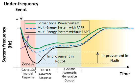
Figure 1. Expected influence of fast active power regulation (FAPR) in under-frequency events.
2. Testing of FAPR Converter Control Through PHIL
In this section, a combined droop- and derivative-based FAPR control method is tested on the PHIL. The combined droop- and derivative-based FAPR is a control strategy, which modulates injected active power according to the derivative of deviation of the frequency from its nominal value. The combined droop- and derivative control-based FAPR implementation in the RSCAD software is depicted in Figure 2. The error in frequency is fed to the derivative controller as input, which is passed through the dead-band, here the dead-band is of negligible value because the immediate response of the controller is a priority during the containment period. Further, the frequency error signal is applied to the derivative block, which has been realized by combining a low pass Butterworth filter and first-order washout filter. The cutoff frequency of the low pass Butterworth filter is 0.5 Hz. The time constant and gain of the washout filter are 10−5 s and 8 × 10⁻⁵ s, respectively. The parameters of the combined droop and derivative controller is selected depending on the amount of power to be regulated.
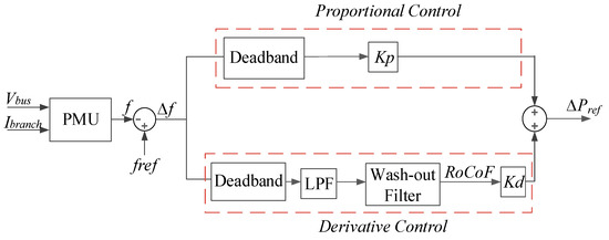
Figure 2. Combined droop- and derivative-based FAPR control.
Further, this signal is multiplied with a user-defined gain called derivative gain Kd, which shall define the response sensitivity of the derivative block. However, the derivative control block alone cannot mitigate the frequency discrepancy, because the derivative block output will only be active during a large dynamic frequency deviation and for the rest of the time (i.e., for example, when the frequency is settled at 49.6 Hz due to the load imbalance after the point of NADIR) the result of the derivative block shall be zero. Therefore, a cascaded droop and derivative block need to be active for improvement in both NADIR and RoCoF.
The controller gains kp and kd values are selected by the sensitivity analysis. Figure 3 shows the frequency dynamics for the various values of the controller gains Kp and Kd of the combined droop- and derivative-based FAPR controller. It can be observed that at Kp = 0.73 and Kd = 0.68, the dynamic is oscillatory. For the power system under study, the value of Kp = 0.9 and Kd = 0.4 has been selected.
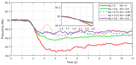
Figure 3. Selection of controllers gains kp and kd for the system under study.
The power system considered under this study is a modified IEEE (Institute of Electrical and Electronics Engineers) 9-bus system, which is used to test the controllers with the topology depicted in Figure 4. The conventional IEEE 9-bus system is altered by adding two wind power plants which contribute 52% of the power share. It is noteworthy that the wind turbine models used here are full scale not aggregate models. Table 1 describes the load flow results of the modified IEEE 9 bus system that is given in Table 1. Moreover, it is worth mentioning that the total generation and load balance has been maintained as the same as a standard IEEE bus system. The penetration of renewables has not been increased just by increasing the active power from the wind turbines but rather replacing synchronous generators. At each generation and load bus, the integrity of voltage and active power balance has been maintained similar to the standard IEEE 9 bus system.
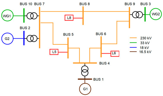
Figure 4. Modified IEEE 9 bus model with a 52% wind generator share.
Table 1. Load flow results of the modified IEEE 9 bus system.
| Component | G1 | G2 | WG1 | WG2 | L5 | L6 | L8 |
|---|---|---|---|---|---|---|---|
| MW | 73.4 | 78.2 | 82.6 | 84 | 125 | 90 | 100 |
| MVAr | 33.8 | −1.8 | 0 | 0 | 50 | 30 | 35 |
The combined droop- and derivative-based FAPR control strategy has been tested on the PHIL test setup under the following conditions: (a) Device under test is connected at bus 7 (Figure 4), (b) the power system is a modified IEEE 9 bus system that has a 52% penetration of type-IV wind power generation, as given in Figure 4, (c) a 5% sudden increase in the load at bus 8 (Figure 4) and (d) FAPR controller is active for 10 s. The steps adopted for the testing of FAPR through PHIL are as follows.
-
Development of the power system model (modified IEEE 9 bus system) on an EMT-based software RSCAD [3] and the power system model is compiled to execute on the RTDS NovaCor.
-
In order to emulate the behaviour of bus 7 at the output terminals of the grid emulator, the voltage and frequency of bus 7 of the modified IEEE 9 bus system at which the type 4 wind generator is connected was sent from RTDS to RTT through an aurora protocol, as depicted in Figure 5. The active power for the DUT is taken from the local grid at 400 V and 50 Hz RMS. The grid emulator is a back-to-back (B2B) converter. The output of grid emulator is connected to the AC side of the DUT, as shown in Figure 5. The DC side of the DUT is connected to the dc bus of the B2B link of grid emulator.
-
As RTDS and the real-time target both are running in real-time, the combined droop- and derivative-based FAPR control method was implemented in RSCAD. The current reference generated by the FAPR controller for the injection of active and reactive power are Id_ref and Iq_ref. These current references were fed to the device under test, as shown in Figure 5. The device under test output power depends on the value of the current reference. The signals corresponding to the three phase output current of the DUT is fed to the simulated grid, as shown in Figure 5.
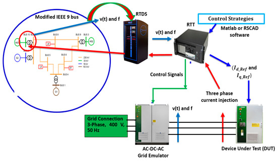
Figure 5. Illustration of FAPR control testing through PHIL.
From Figure 6 and Figure 7, the dynamics of the active power injection by the combined droop- and derivative-based FAPR control method and its counter effect on the frequency can be seen. In addition, the active power injection and frequency curves are complying with the compliance criteria for FAPR. The frequency NADIR and RoCoF are within the defined limit. NADIR is improved from 49.64 to 49.82 Hz. While ROCOF is improved from 0.28 Hz/s to 0.04 Hz/s. The gain of the controller is tuned (K = 1 pu) to inject 10% of the rated power. It is injecting 10% of the rated power. After a few seconds, the power injection decreases due to a decrease in the requirement of power and improvement in the frequency. The rise time of active power is 510 ms, which is within the specified limit. The FAPR controller is active for 10 s. The frequency insensitivity band of ±30 mHz has been considered. The power system is stable and the implemented FAPR has not contributed negatively to the damping of power oscillations of the electrical system.
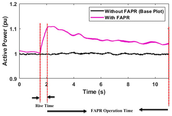
Figure 6. Illustration of FAPR control testing through PHIL.
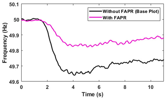
Figure 7. Dynamics of frequency due to the FAPR controller.
References
- Yan, X.; Mohamed, S.Y.A. Comparison of virtual synchronous generators dynamic responses. In Proceedings of the 2018 IEEE 12th International Conference on Compatibility, Power Electronics and Power Engineering (CPE-POWERENG 2018), Doha, Qatar, 10–12 April 2018; pp. 1–6.
- Soni, N.; Doolla, S.; Chandorkar, M.C. Improvement of Transient Response in Microgrids Using Virtual Inertia. IEEE Trans. Power Deliv. 2013, 28, 1830–1838.
- RTDS Technologies Inc., RSCAD Modules. Available online: https://www.rtds.com/thesimulator/our-software/rscad-modules.


