 +1 credit
| Version | Summary | Created by | Modification | Content Size | Created at | Operation |
|---|---|---|---|---|---|---|
| 1 | Leszek Resner | + 6084 word(s) | 6084 | 2021-05-20 08:05:16 | | | |
| 2 | Conner Chen | -8 word(s) | 6076 | 2021-06-01 11:36:43 | | |
Video Upload Options
The submarine cables manufacturing industry is growing very rapidly. Solutions used so far, usually adapted from designs of land cables, do not fulfil the new, more demanding requirements. The phenomenon of water ingress into insulation and its absorption are basic factors determining the service life of submarine cables. The radial water barrier is the only effective component of cable design that may guarantee the required minimum 30-year longevity of submarine cables.
1. Working Conditions and Operational Factors of Submarine Cables
At the very beginning specifications, contracts and tender documentation clearly define the following: cables must be fully suitable and adapted to their service life in the marine environment. The cable will be covered with seawater and all its cores will be permanently immersed in seawater throughout its entire service life. The conductors must be suitable for continuous operation in a flooded submarine cable at a strictly defined depth (up to 60 m or even much more) for a period of up to 30 years or more.
The main factor limiting the service life of the cable is the quality of insulation, time of its degradation, and loss of dielectric properties. When the XLPE is not capable of withstanding the stress of the electric field for which it was designed (e.g., Ei = 5.4 kV/mm), breakdown occurs in the weakest point of the system [1]. The process of degradation of XLPE insulation can be divided into two types. Degradation is caused mainly by micro-voids and contamination—particles present inside insulation material. The second type is degradation caused by any change in physical or chemical properties, or due to trapped charges. This type of degradation is not limited to a specific local area but may affect a certain section of insulation. The degradation mechanism is not related to temperature, because it should not exceed 90 °C during normal cable operation. According to standards, that is the allowed maximum conductor temperature during the normal operation. In regards to the emergency situation, different standards describe different criteria of acceptance, for example, IEC 63026 allows for short-circuit 5 s maximum duration with maximum conductor temperature of 250 °C. US standards, for example, ICEA S-97-682, ICEA S-97-639, and ICEA S-97-649, accepting up to 1500 h of a total cable lifetime in elevated temperatures of 130 °C for XLPE and 140 °C for Ethylene Propylene Rubber (EPR) insulation [2]. The main factor leading to cable failure in long-term cable service is the phenomenon of electrical and electrochemical tree formation, often referred to as water tree. After years of continuous improvement and development of materials and manufacturing technologies, the water tree phenomenon remains the primary cause of cable failures and a factor determining their service life [3]. After many decades since the introduction of the XLPE material in cable manufacturing (cables with the use of this material were first manufactured in the 1960s), thanks to numerous developments involving improvement of material cleanliness, technology, and process, cable longevity has been significantly extended (from several to several dozen years). Nevertheless, due to the environment of their operation, the main factor limiting the service life of submarine cables is the (electrochemical) water tree phenomenon. Water tree starts and spread inside the XLPE insulation, which is exposed to high voltage and contains moisture. An additional factor responsible for their formation is all kinds of contaminations, inclusions, or micromechanical damages. Due to their nature and mechanism of formation, water trees can be divided into two types: vented and bowtie trees (Figure 1). Trees of the first type occur at the interface of semi-conductive screen and insulation and their growth is visible towards insulation. Bowtie trees, however, appear inside insulation and their growth is in two directions reflecting the direction of the lines of the electric field [4]. It has been found that the increase of water trees is reduced by hydrostatic pressure and compressive strength, whilst their increase is facilitated by tensile stress. Results of numerous researches confirm that the factor necessary for the formation of water trees is the level of relative humidity (RH) >70%. By delaying water ingress by application of radial water barriers in cables, it is possible to extend the time until critical levels of humidity in insulation are reached, even up to a few decades. It must be noted, however, that it is not the presence of water trees that will determine when the insulation breakdown occurs, but their size, the growth rate, and the amount per specific unit of volume [5].
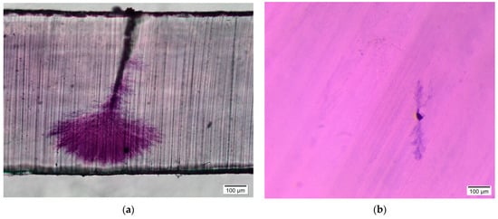
Figure 1. Examples of the electrochemical water trees: (a) vented type and (b) bowtie type.
In addition to the working environment, which may be considered as extreme for the transfer of electricity, there are also several other factors that cables or even semi-finished products are exposed to during production process, transport, or installation, which may have an impact on cable service life. Starting from the insulation extrusion process, XLPE insulation along with two semi-conductive layers, so-called screens, is extruded in temperatures ranging between 120 °C and 140 °C. The temperature of the material must be closely monitored and controlled to allow initiation of peroxide decomposition, which is part of the material granulate and its role is to initiate the reaction of cross-linking during the stage of extrusion. XLPE material is being cured (cross-linked) continuously. During this process temperature on the surface of the insulation, the screen can reach up to 300 °C. In such conditions, extruded insulation travels along the curing tube in the atmosphere of nitrogen at a pressure of above 8 bar. Required quality and effectiveness of the cross-linking process are ensured through constant monitoring and control of such parameters as temperatures of individual heating zones of extruders, load, pressure, speed, rotations, and position of conductor with insulation inside the curing tube, et cetera. Right after the process of cross-linking the insulated core undergoes the process of conditioning, also referred to as degassing [6]. During this process, by-products are generated during the process of cross-linking with peroxide, such as methane, diffuse insulation. This process is crucial, because during cable operation, methane, which has remained after cross-linking, may cumulate in the areas of joints or terminations and can even lead to an explosion. During chemical cross-linking with the participation of peroxides (dicumyl peroxide is commonly used for this purpose), in addition to methane, other by-products are also generated, for example, polar compounds such as cumyl alcohol, acetophenone, or alpha-methylstyrene. The latter, however, is not entirely removed during the degassing process and is now a subject of considerations and research regarding their impact on the cumulation of electric charges in insulation [7]. This is of particular importance for DC cables. During each stage of the production process, cores are bent, spooled on reels or trays with necessary tension, and are in contact with various construction elements of machines. Application of metallic screen (concentric neutral), extrusion of a lead sheath or outer sheath, and then laying-up three cores or application of armour must also be performed in a strictly defined technological regime. Installation of submarine cables is performed with the use of special cable installation vessels, on board of which special cranes, carousels, baskets, winches, and tensioners are installed. During the cable laying operation the vessel is floating on the waves, the cable is touching the sea bed and is being buried in it during the ploughing operation or covered with special protective mattresses (concrete) [8]. All this is very important and has an impact on which types of materials and which technology should be selected. No damage may occur on any layer of the cable during any of these operations. In the event of exceeding allowable pulling force or minimum bending radius, microcracks, breaks, or deformations of various layers may occur, which will lead to a reduction of cable service life.
The extreme environment in which submarine cables must operate, specialised equipment and conditions of installation, and costs of repair or replacement of these types of cables are incomparable to land cables. Costs of renting a specialised vessel, crew, and the time needed for necessary repairs are immense. Due to their costs and functions, export and interconnector cables are repaired quite often, however, broken inter-array cables are left on the seabed and new ones are installed. Offshore wind farms can currently reach several gigawatts of power, a single wind turbine is capable of supplying electricity to tens of thousands of households. The Heliade-X turbine from General Electric, for example, can produce 312 MWh in one day, which allows supplying electricity to 30,000 households [9]. The cost of losing power due to cable failure can be enormous. This is why there are so many strict requirements with regard to these designs.
2. Dry and Semi-Dry Cable Designs—Advantages and Disadvantages of Radial Water Barriers Used
Of all the types of submarine cables, it is dry and semi-dry designs that have been the most popular. A long history of their use in land cables in humid environments and experience in the field of submarine HV cables has led to them still being widely in use [10]. The technology of extruded lead used for the protective layer has been well received in the case of interconnector cables and has been in use since the very beginning of using submarine cables, especially with popular technology of oil and paper insulation. Lead is a relatively cheap material, however, when the total cost is taken into account, in other words, the amount of lead along with the processing energy costs of extrusion, there is little difference between this technology and others, for example, longitudinally welded aluminium. Lead is easy to process and rather soft, which makes it easy to wind onto the drums and carousels during the process. It perfectly blocks against water penetration, is a great protective layer against organic solvents, and is not as susceptible to oxidation as aluminium. The extrusion process guarantees that its barrier properties are maintained along the entire length and across the entire cross-section of the cable. On the other hand, however, the same properties of lead that make it such a great barrier against moisture, make it extremely heavy. Because of its high atomic mass, the weight of the cable after application of lead sheath significantly increases. Nevertheless, this can be both an advantage and a disadvantage, depending on the nature of a specific project. Due to the environment in which the submarine cables are to operate, it is very crucial to firmly embed them on the seabed to ensure that they do not move during the movement of the seabed, currents, or in emergencies, such as catching on fishing nets. In this case, therefore, the heavier the cable the better it is for this purpose. On the other hand, the large weight of the cable limits the length of a single manufacturing section. Because the large weight of the cable makes logistics (take-up devices, transport, installation) more difficult, it is necessary to produce shorter lengths and connect them later. Although various types of connections are used, starting from factory-joints (also called flexible joints) through cable joints up to repair joints, it must be noted that any connection is a “weakest link” of the system. Additionally, lead is prone to microcracking when the minimum bending radius is exceeded. As far as its impact on the natural environment is concerned, opinions are divided. There has been a trend of withdrawing these cables from the market due to environmental aspects, but there are also more conservative markets that consider this type of cable protection as the best and treat the lead itself as a recyclable material, which is hardly harmful to the environment. What definitely speaks for the withdrawal of lead from submarine cables is the fact that it is not applicable for dynamic constructions which are becoming more common and resources are limited, because it is a strategic material in other industries, such as defence and nuclear.
Aluminium is another material that is taken into consideration in terms of an effective water barrier. The aluminium sheath has high mechanical strength, low density, and good electrical conductivity, thanks to which the cable is light, the protective layer is durable and capable of dissipating high short-circuit current, because it can also act as a neutral conductor. During cable operation, the metallic layer is subjected to induced/eddy currents. The main disadvantage of aluminium is its lower resistance to corrosion than in the case of lead. There are three leading technologies of application of this layer on a cable. The first one is extrusion, the second is longitudinal forming of tape and continuous longitudinal welding to close the tube formed, and the third in the form of thin Al tape covered with an adhesive layer whose edges are connected by glue applied in the overlap. Extrusion of aluminium takes place at high temperatures (approximately 500 °C), which is twice as high as that of lead. The extruded sheath is seamless, which guarantees water-tightness and homogeneity of the layer along the entire cable length. However, because the process must be performed at high temperatures, which results in high energy consumption, and the fact that it takes much time with low efficiency and long change-overs, it is very problematic. Additionally, due to process limitations, the layer of aluminium must be of a specific thickness, which is a function of core diameter and used tooling. The thickness must not be lower than 1 mm. High temperature during the aluminium extrusion process forces the use a few layers of special foamed semiconductive tapes, to prevent insulation overheating during the process and to provide a good connection between aluminium and semiconductive insulation screen. Because of the bending radius, which is of particular importance during the manufacturing process, aluminium sheath is additionally corrugated. Cable designs with corrugated aluminium have been in use since the 1960s. The corrugated aluminium sheath has high resistance to compression, excellent anti-vibration properties, and low sensitivity to mechanical damage. It can be used in cables installed in areas with mild vibrations, such as under bridges. Corrugation, however, increases cable diameter, which in turn results in shorter cable lengths due to transport limitations. Additionally, the corrugated layer must adhere closely to the core, and appropriate and evenly distributed contact between the aluminium layer and the semi-conductive insulation screen is of particular importance. Otherwise, there is a high risk of discharges, which may lead to defects of the insulation screen and, as a result, to failure of the cable. Many cases of this issue, which occur on an alarming scale on the Asian market, where this type of design is very common, can be found in available literature [11].
The second method, namely, longitudinal tape formed with a continuous closing weld along its length, is mainly used for smooth aluminium sheaths. A smooth layer can have contact with the semi-conductive layer along the entire length of the core, thanks to which the field distribution in the contact area is uniform, thus partial discharges are avoided. This type of design is easier to manufacture, but it requires a large bending radius. To reduce the bending radius, the outer sheath is extruded in the same process as the application of welded tape. Aluminium tape protected with a layer of the outer sheath, for example, HDPE, is not that susceptible to deformations or any other damages. On the other hand, however, the process of longitudinal tungsten inert gas (TIG) or laser welding with simultaneous extrusion of the thermoplastic sheath is very sensitive to all kinds of disturbances. During the forming process, aluminium tape must be evenly cut, its forming must be exactly in the axis of the whole manufacturing line, welding is continuous and monitored with the use of cameras as well as with a method making use of eddy currents. This eddy current checker is designed to control and report each weld defect. As was the case with aluminium extrusion, this process is very complex and requires high accuracy. Therefore, with longer sections of submarine cables, it may turn out to be very costly and prone to defects.
The third technology, which is in the form of a thin aluminium tape with an even thinner adhesive layer, connected longitudinally in the overlap is most common in the production of MV cables, but is also used in land HV cables and has been adapted in submarine cables to form the semi-dry design. Aluminium tape supplied by the manufacturer is covered on one side with an adhesive layer of the copolymer. The thickness of aluminium is usually between 150 µm to 200 µm, whereas the layer of polyethylene (PE) copolymer is usually approximately 50 µm. During the process, the tape is formed around the core and then the overlap formed is connected with the use of glue applied continuously. Due to its small thickness, the aluminium laminate tape cannot act as the neutral, therefore this design requires the application of a metallic screen in the form of copper or aluminium wires underneath the tape. The IEC 60840 standard divides cables with Al tape underneath the outer sheath into three categories. The first is combined design (CD), where the Al tape acts as the water barrier but also partially or entirely as a neutral. In the second type, separate design (SD), the Al tape covered with copolymer acts only as a water barrier, whereas the role of the neutral is fulfilled by other components, such as Cu or Al wires. The third category, separate semi-conductive design (SscD) uses a solution with the thin Al tapes covered with copolymer on the top and with a thin semi-conductive layer on the bottom. The thin semi-conductive layer touches semi-conductive non-metallic tapes applied over the screen wires. The thickness of Al tape and semi-conductive tape usually amounts to approximately 50 µm. The SscD category is used least frequently (mainly in Japan) [11]. The most common, on the other hand, is the SD design, with the Al tape covered with a thin adhesive layer (copolymer) on one side. The semi-dry design is the cheapest with an efficient and relatively easy to control production process and the lowest consumption of materials. However, since the tape is joined with the use of glue applied in the overlap, which creates the possibility of water diffusion in this critical point, this design is yet to be qualified as a valid alternative to the dry solutions. The relatively low thickness of the tape (150–200 µm) makes it susceptible to deformations and mechanical fatigue, which is questioned as a solution to be used in submarine dynamic cables. Three different designs using aluminium as barrier material are presented in Figure 2.
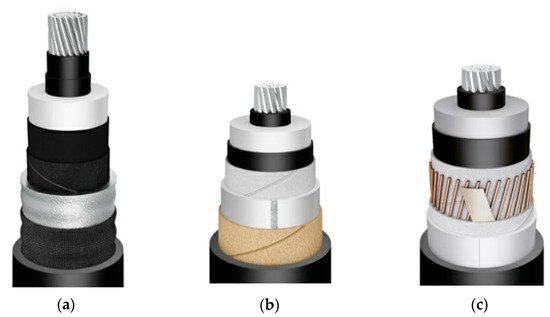
Figure 2. Cables construction with different aluminium water radial barriers: (a) extruded aluminium corrugated sheath; (b) smooth welded aluminium tape; and (c) laminated aluminium tape.
As far as copper is concerned, it is an excellent alternative to lead, at least in terms of its mechanical and electrical properties. Additionally, copper has excellent fatigue properties, enabling it to be used in dynamic cables. Its excellent electrical properties, much lower resistivity than lead, make it possible to use lower thickness for this tape than in lead sheaths. What is more, because of the lower density of copper than that of lead (by approximately 20%), the weight of the cable can also be much smaller. Copper is a soft metal that can be easily formed, which makes it possible to use it in cable manufacturing. Unfortunately, due to its high melt temperature (1396 °C), copper extrusion is not used in cable manufacturing [12]. Such a high temperature of the process would cause overheating, which would lead to damage of other layers over which copper would be extruded, namely, the insulation screen and the insulation itself. Therefore, copper is mainly used in designs where copper tapes are formed around the cable cores and longitudinally welded or glued. As with aluminium tape, after forming and welding the copper tape can be corrugated or left smooth. For designs with smooth tape, it is covered with an adhesive layer and to improve its mechanical and fatigues properties during bending, the outer sheath is extruded directly over it in the same process. Therefore, it is impossible to replace lead with copper for designs with extruded seamless sheaths, and copper can only be used in designs with longitudinally joined tapes, as was the case with Al tapes. A huge disadvantage of using copper, which has not been taken into account so far, is certainly the high price of copper. Therefore, copper tapes can only be considered as probable solutions in very demanding and costly solutions, such as export DC cables. In the case of inter-array cables, or even some DC export cables, the share of the price of copper as a radial water barrier in the total cost of the cable would be so high that this solution would be highly uneconomical. This is especially valid at present when the offshore power industry is under great pressure to optimise and reduce the total costs of wind farms. It is worth noting that all cables used for offshore wind farms (export, inter-array, and very often some sections of land cables) can even constitute up to 10% of the total value of an entire wind farm, whilst with installation, the share reaches up to several percent [13]. Because developers place great emphasis on cost optimisation in every aspect of offshore wind farm projects, cable designs are also carefully analysed in this regard.
Table 1 shows how the cost of the single-core cable is correlated in different constructions of the radial water barrier. For the analysis construction of 1000 mm2 aluminium conductor with insulation for 220 kV cable was chosen. Because the material costs are dependent on many circumstances, for example, oil or metal stock price, long-term agreements between manufacturer and supplier, or the ordered amount, the price can fluctuate depending on the manufacturer. Because costs of the materials are sensitive data for each producer, Table 1 presents an example of the costs for each construction expressed in an equivalent unit, which allows comparing of each individual construction material’s costs in reference to the six types of radial barrier.
Table 1. Single-core costs comparison for the different radial water barrier constructions.
| Construction Layer | Lead | Extruded Aluminium (Corrugated) | Welded Aluminium (Smooth) | Aluminium Laminated | Welded Copper (Corrugated) | Copper Laminated |
|---|---|---|---|---|---|---|
| Conductor and insulation with semiconductive layers | 10.00 | 10.00 | 10.00 | 10.00 | 10.00 | 10.00 |
| Copper screen wires, equalizing tape and semiconductive tapes | - | - | - | 5.9 | - | - |
| Aluminium laminated tape with one side copolymer layer with glue for overlap | - | - | - | 0.17 | - | - |
| Aluminium tape for welding with extruded adhesive layer | - | - | 2.09 | - | - | - |
| Copper tape for welding without copolymer | - | - | - | - | 11.61 | 5.22 |
| Lead TYPE E with protective semiconductive tapes | 8.40 | - | - | - | - | - |
| Aluminium rod for extrusion with protective semiconductive tapes | - | 1.66 | - | - | - | - |
| Outer sheath HDPE | 0.77 | 0.80 | 0.72 | 0.74 | 0.76 | 0.73 |
| Sum | 19.17 | 12.46 | 12.81 | 16.81 | 22.37 | 15.95 |
Based on the material costs comparison, welded copper (corrugated) construction is the most expensive due to the amount of copper tape used in this design. However, lead construction, which consists of a much higher amount of the barrier material than the copper one, if we compare the thickness of both layers, is only approximately 14% cheaper. Aluminium laminated construction has approximately 25% lower costs, compared to the copper corrugated design, but due to the requirements of the copper wire screen it is not the cheapest one. Extruded aluminium (corrugated) and welded aluminium (smooth) are almost at the same level, the difference is because of the technology involved. In the first construction, raw material is in the form of aluminium rods, and in the second design, the aluminium tape is used which is more expensive even if it is used in a slightly smaller amount because of the thinner layer. The corrugated or smooth design has an impact on the amount of the HDPE outer sheath, but the share of this layer is rather small in the whole costs of the cable construction.
Cost is one of many factors in selecting a cable design solution. The risk assessment in the context of the reliability of a cable design, under the demanding operating conditions of the cable, plays a huge role. Taking into account, inter alia: barrier properties, production process, installation risks, influence on the environment, and cable properties in itself, the designer need to optimized each construction individually. The evaluation of some basic properties, depending on the type of the radial water barrier used is presented in Table 2.
Table 2. Advantages and disadvantages of different radial water barriers in dry and semi-dry cable designs.
| Technology | Design | Barrier Properties | Processing | Installation | Environment | Mechanical Properties | Electrical Properties | Costs |
|---|---|---|---|---|---|---|---|---|
| Lead | Dry | +++ | +++ | + | + | + | + | + |
| Extruded aluminium (corrugated) | Dry | +++ | + | ++ | +++ | ++ | ++ | +++ |
| Welded aluminium (smooth) | Dry | +++ | ++ | ++ | +++ | ++ | ++ | +++ |
| Aluminium laminated | Semi-Dry | ++ | +++ | +++ | +++ | ++ | ++ | ++ |
| Welded copper (corrugated) | Dry | +++ | ++ | ++ | +++ | +++ | +++ | + |
| Copper laminated | Semi-Dry | ++ | +++ | +++ | +++ | +++ | +++ | + |
3. Directions of Development in the Field of Water Barrier in Submarine Cables
For HV AC cables, contrary to obsolete lead extrusion technology, the most effective is the metallic tapes welding method. Technology and design of longitudinally welded aluminium and copper tapes for water-blocking applications are constantly developed and well-known in land applications. Tapes are welded with the use of two methods: TIG (tungsten inert gas) welding, which is also called GTAW (gas tungsten arc welding), as well as laser welding. The advantage of the latter method is the fact that it does not generate by-products and ensures weld cleanliness. The weld is smoother and does not contain anything apart from the welded material. Additionally, laser welding is faster than TIG welding. Unfortunately, it is more demanding in terms of accuracy. Edges of tape formed around the core circumference must be evenly in contact with each other, any irregularity and local lack of contact will result in weld defect. TIG welding, on the other hand, involves the use of inert gases (most common is the mixture of helium and argon). Welding is performed in the atmosphere of these gases with the use of a non-consumable electrodes made of an alloy of tungsten with various types of oxides (e.g., thorium, zirconium, lanthanum, and cerium). The process is slower than in laser welding, but it does not require such precision in tape forming around the core. Additionally, it consumes less energy.
As far as dynamic dry cables, which have lately become quite a challenge in the off-shore renewable energy industry, are concerned, using longitudinally welded and corrugated copper tapes are now the most considered potential solution among cable designers. The design of dynamic cables must reconcile two fundamental requirements, that is resistance to material fatigue caused by its constant bending as well as mechanical resistance to hydrostatic pressure. Fulfilling both these requirements is very problematic in standard designs used currently, that is in cables with a lead sheath or smooth aluminium sheath. It has been found, that forming corrugation on the copper tape significantly improves its resistance to bending, but hydrostatic pressure occurring on the seabed can lead to its deformation and damage. To improve the resistance of the corrugated copper tube to the pressure exerted by the seawater at depths of more than several dozen meters or even up to a few hundred meters, special geometry of corrugation matched to a specific purpose is used. Depth of corrugation, tape thickness, and corrugation pitch are all very important and play a huge role in selecting appropriate construction (Figure 3). A shorter pitch with a bigger depth of corrugation improves both resistance to hydrostatic pressure as well as to bending. For example, when the tape with a thickness of 0.8 mm, corrugation pitch of 8 mm, and depth of 7 mm is applied on a cable, it can be installed at the depth of up to 800 m. For the same thickness of the tape, but with pitch 6.5 mm and depth of corrugation of 9 mm, the depth at which the cable can be installed increases to 1100 m (data taken from the patent no. US 2015/0248951 A1 issued in 2015) [14].
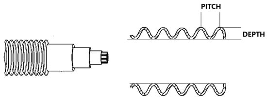
Figure 3. Sketch of a cable and corrugated tape.
Due to the high cost of the material, complex process of application, the copper tape is only used in subsea cables with high margins, such as export cables or special use cables (for example for transmitting power to platforms extracting petroleum from large depths.
As far as inter-array cables are concerned, which connect individual platforms, the most common design, which offers a compromise between price and quality and functionality, is the semi-dry solution with aluminium tape with glued overlap. Unfortunately, the weakest link in this solution is the glued overlap itself. What is more, the water barrier in the form of aluminium laminate applied in a standard way is not suitable for dynamic inter-array cables. With wind turbines increasing in size and installed at greater distances from the shore on floating wind farms, special types of cable designs must be used. When all the above-mentioned factors, operating conditions, requirements, functionality, productivity, and profitability are taken into account, the best solution would be finding such a material, which could be extruded (uniform seamless structure) and which would constitute a complete barrier against water ingress to cable insulation in various, often extreme, conditions. Additionally, it would have to be flexible, resistant to fatigue, relatively cheap, and easy to process. Achievement of all these requirements seems impossible and unattainable for one type of material, especially when some requirements are often mutually exclusive. Construction materials with high resistance to water penetration and moisture diffusion usually have high density, which is why metallic tapes are so popular even today. On the other hand, high density and orderly structure, which makes such materials resistant, also makes them stiff, difficult to process, and prone to microcracking, thus degrading their water-blocking properties. This issue also concerns plastics, such as polymers like polytetrafluoroethylene (PTFE), polyetheretherketone (PEEK), polyphenylene sulphide (PPS), or polysulfone (PSU), which have excellent resistance to water absorption and resistance to hydrolysis at elevated temperature, but they are not flexible enough and their processing requires high temperatures.
The solution to this issue may be the use of a system consisting of several materials, selected in such a way as to make sure that they are mutually compatible in basic range resulting from product (i.e., cable) specification, but additionally, which would complement each other in other functions. Water barrier properties in other products made of plastics are achieved by using several different materials arranged in layers with various properties. Similarly, in the case of cables, there are also discussions regarding the possibility of using several layers, each with different properties. Literature mentions designs that make use of a sheath made of a combination of polyurethane (PU) and polyethylene (PE). This concept consists of combining the outer polymer barrier with low permeability and an inner absorbent layer so that this internal absorbing layer could trap all moisture that would get through the outer layer (Figure 4). By delaying the ingress of water to insulation and thus the critical level of moisture, cable service life could be increased. In the last few years, numerous studies have been conducted with regards to the possibility of designing outer layers of cables’ insulation and it was found that using a special combination and sequence of sheaths based on different types of polymers results in significantly delaying water ingress. A critical level of relative humidity (RH > 70%) would be only reached after several decades, thus delaying the formation of water trees and extending the life of submarine cables.
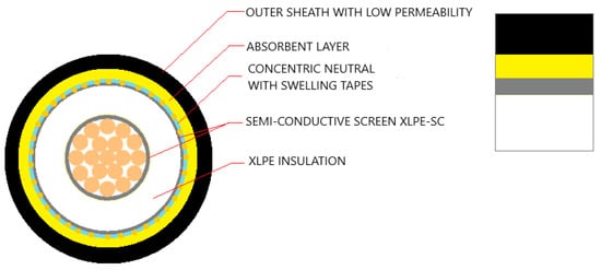
Figure 4. Cross-section of a cable with absorbing layer.
When water permeates through the polymer layer with low diffusion it gets absorbed by the absorbent layer and as a result, the insulation remains dry for a long time. The system is 100% polymer, therefore the issues relating to bending, fatigue, cracking, and deformation due to hydrostatic pressure are minimalized. Unfortunately, the hygroscopic layer has a limited service life, which may be a disadvantage. However, it is believed that it is possible to design such a system that will allow for cable operation for more than 30 years, which is as much as is expected from inter-array cables today. This idea introduces a new class of solutions. The design not only allows for a significant delay in reaching a critical level of humidity in insulation but also makes it possible to control this time. By knowing the exact properties of the material (diffusion mechanism) and cable construction (thicknesses, geometry), it is possible to model the time when the critical degree of relative humidity would be reached [15]. Water ingress depends on the rate of diffusion, water absorption, the initial water content in materials used in the cable, and cable temperature. There are already numerical models based on the finite element method, which make it possible to forecast the time until 70% RH is reached in insulation, depending on the materials used, their thicknesses, and the order in which they have been extruded in the cable [16]. To describe this phenomenon, the solubility coefficient (S), the diffusion coefficient (D), and the permeability coefficient (P) can be used. Water ingress to polymers may be described with the use of Henry’s law. Water solubility in polymer p is proportional to the partial water pressure pi above the polymer.

Diffusion is described by Fick’s law. Diffusion coefficient D is proportional to the rate of diffusing molecules and depends on the temperature, specific construction of the core, and substance viscosity (in this case particles behave in accordance with the Stokes–Einstein equation). This coefficient determines the ability of molecules to diffuse under the concentration gradient. In one-dimensional space, the diffusion flux J is as follows:

Permeability (P) provided that (D) is constant, is:

The principal laws and principles presented above are now used in research and studies regarding a combination of coating materials that would allow designing submarine cables with polymer barriers that would meet customer expectations and which could be used in dynamic cables [17].
4. Thermoplastic Polyurethane (TPU) as a Potential Material for Applications in New Designs of Submarine Cables
The permeability of block copolymers has already been a focus of numerous researches since the 1960s. These studies revealed many interesting properties of these materials and opened a new perspective on the phenomenon of diffusion and permeability. Block copolymers represent a very wide range of materials with a great variety of properties. One of the best examples of block copolymers is thermoplastic polyurethanes (TPU), which can be synthesized from several types of substrates (e.g., polyether, polyester, or polycarbonate oligomers, aromatic or aliphatic diisocyanates, and chain extenders, etc.). Polymers obtained this way can have very different properties. Block copolymers consist of hard and soft segments. Depending on the kind of segments and their functionalities, these materials can also have various properties. High strength, resistance to hydrolysis, resilience, and the ability to maintain good properties at low temperatures, are only several of many properties that can be obtained by thermoplastic polyurethane. Thanks to these properties, TPU is now used in various types of measurement cables, supply cords, power cables, control wires used in opencast mining, and transmission cords for radio and television. As far as the water sorption property is concerned, it is believed that soft TPU chains play an important role in this regard. Hard blocks do not have such an influence on the water absorption properties of TPU. The chemical structure, polarity, and molecular weight of hard blocks, on the other hand, are very important concerning resistance to strong solvents. Hard blocks are usually impermeable to small molecules and can act as simple crosslinks, which reduce general permeability. Permeability of block copolymers in TPU depends on various factors, such as chemical structure, polarity, the weight ratio between soft and hard blocks, phase separation, and material morphology [18]. Block copolymers are materials that could be widely used in new designs of submarine cables. Research regarding their water permeability, absorption, and diffusion may lead to the introduction of new and innovative designs of submarine cables. The possibility to modify and select an appropriate combination of materials together with the development of optimal designs could be a solution for more demanding applications, such as submarine dynamic cables.
References
- Featherstone, J.; Neumann, A.; Wan, J.; Harris, L. Full Scale Wet Age Testing of XLPE Insulated Power Cables in Salt Water; Jicable’19: Paris, France, 2019.
- Lv, H.; Lu, T.; Xiong, L.; Zheng, X.; Huang, Y.; Ying, M.; Cai, J.; Li, Z. Assessment of thermally aged XLPE insulation material under extreme operating temperatures. Polym. Test. 2020, 88, 106569.
- Mishra, S. Identification of Failure Root Causes Using Condition Based Monitoring in Solid Insulations, Master of Technology in Power Electronics; Department of Electrical Engineering National Institute of Technology: Rourkela, India, 2015.
- Ross, R.; Smit, J. Composition and growth of water trees in XLPE. IEEE Trans. Electr. Insul. 1992, 27, 519–531.
- Karhan, M.; Uzunuoğlu, C.P.; Issi, F.; Uğur, M. Segmentation of Vented Water Trees in Microscopic Images Using Image Processing Techniques. In International Scientific Conference; ISCFEC: Gabrovo, Bulgaria, 2017.
- Andrews, T.; Hampton, R.N.; Smedberg, A.; Wald, D.; Waschk, V.; Weissenberg, W. The role of degassing in XLPE power cable manufacture. IEEE Electr. Insul. Mag. 2006, 22, 5–16.
- Maeno, Y.; Hirai, N.; Ohki, Y.; Tanaka, T.; Okashita, M.; Maeno, T. Effects of Crosslinking Byproducts on Space Charge Formation in Crosslinked Polyethylene. IEEE Trans. Dielectr. Electr. Insul. 2005, 12, 90–97.
- Worzyk, T. Submarine Power Cables: Design, Installation, Repair, Environmental Aspects; Springer Science & Business Media: Berlin/Heidelberg, Germany, 2009; ISBN 3642012701.
- Offshore Wind. 11 November 2020. Available online: (accessed on 27 April 2021).
- Hamdan, M.A.; Pilgrim, J.A.; Lewin, P.L. Effect of Sheath Plastic Deformation on Electric Field in Three Core Submarine Cables. In Proceedings of the IEEE Conference on Electrical Insulation and Dielectric Phenomena (CEIDP), Cancun, Mexico, 21–24 October 2018; pp. 342–345.
- Cao, J.; Wang, S.; Li, N.; Huang, B.; Zhu, Y.; Chen, J.; Liu, Y.; Wang, X.; Lian, R. Analysis on buffer layer discharges below the corrugated aluminum sheath of XLPE cables and comparison with other metal sheath structures. In Proceedings of the IEEE 3rd International Conference Circuits, System Devices (ICCSD), Chengdu, China, 23–25 August 2019.
- Sonerud, B.; Eggertsen, F.; Nilsson, S.; Furuheim, K.M.; Evenset, G. Material considerations for submarine high voltage XLPE cables for dynamic applications. In Proceedings of the 2012 Annual Report Conference on Electrical Insulation and Dielectric Phenomena (CEIDP), Montreal, QC, Canada, 14–17 October 2012; pp. 890–893.
- O’Keeffe, A.; Haggett, C. An investigation into the potential barriers facing the development of offshore wind energy in Scotland: Case study—Firth of Forth offshore wind farm. Renew. Sustain. Energy Rev. 2012, 16, 3711–3721.
- Tyrberg, A.; Eriksson, E. Radial Water Barrier and a Dynamic Highvoltage Submarine Cable for Deep Water Applications. U.S. Patent 2015/0248951 A1, 27 October 2015.
- Furuheim, K.; Nilsson, S.; Hvidsten, S.; Hellesø, S. Water Diffusion Barrier—A Novel Design for High Voltage Subsea Cables. In Proceedings of the Nordic Insulation Symposium, Trondheim, Norway, 9–12 June 2013.
- Hellesø, S.M.; Hvidsten, S.; Balog, G.; Furuheim, K.M. Calculation of Water Ingress in a HV Subsea XLPE Cable with a Layered Water Barrier Sheath System. J. Appl. Polym. Sci. 2011, 121, 2127–2133.
- Helleso, S.M.; Henoen, V.C.; Hvidsten, S. Simulation of Water Diffusion in Polymeric Cables Using Finite Element Methods. In Proceedings of the Conference Record of the 2008 IEEE International Symposium on Electrical Insulation, 2008 (ISEI 2008), Vancouver, BC, Canada, 9–12 June 2008; p. 595.
- Jonquières, A.; Clément, R.; Lochon, P. Permeability of block copolymers to vapors and liquids. Prog. Polym. Sci. 2002, 27, 1803–1877.


