Accuracy Improvement in Double-Sided Incremental Forming Process: History
Please note this is an old version of this entry, which may differ significantly from the current revision.
Contributor: , , ,

Low geometric accuracy is one of the main limitations in double-sided incremental forming (DSIF) with a rough surface finish, long forming time, and excessive sheet thinning. The lost contact between the support tool and the sheet is considered the main reason for the geometric error. Toolpath compensations strategies improve geometric precision without adding extra tooling to the setup. It relies on formulas, simulation, and algorithm-based studies to enhance the part accuracy. Toolpath adaptation improves the part accuracy by adding additional equipment such as pneumatically or spring-loaded support tools or changing the conventional toolpath sequence such as accumulative-DSIF (ADSIF) and its variants. It also includes forming multi-region parts with various arrangements. Toolpath adaptation mostly requires experimental trial-and-error experiments to adjust parameters to obtain the desired shape with precision. Material redistribution strategies are effective for high-wall-angle parts.

  • incremental sheet forming
  • double-sided incremental forming
  • single point incremental forming
  • geometric precision

1. Introduction

Ideas need to be converted quickly into products and analyzed to meet the requirements of the industrial revolution. Manufacturing processes having less changeover time and tooling cost can fulfill the prerequisite of mass customization and prototype development. The prototype allows improvement in the design in the early stages of product development. Conventional manufacturing processes require a long time and capital for small batch production and prototype development. Forming operations require component-specific and expensive dies as their design and preparation are time-consuming. In recent years, incremental sheet forming (ISF) has gained significant attraction due to its capability for prototype and small-batch productions with short lead time and generic tooling. In ISF, flat metal sheets are incrementally deformed into complex three-dimensional components using a computer numerically controlled (CNC) generic tool. During the forming, the sheet is peripherally clamped. Higher formability, less forming forces, high geometric flexibility, less lead time, low cost for production of customized and low-volume components than stamping and deep drawing are the salient features of ISF. Furthermore, a wide range of materials can be formed such as steel, aluminum, copper, polymers, titanium, etc. It has considerable potential in the aerospace industry, prototyping in automotive, on-site repair for military applications, personalized products in the medical, architecture, etc. [1,2].
Existing experimental configurations for ISF can broadly be classified into three categories: single-point incremental forming (SPIF), two-point incremental forming (TPIF), and DSIF. In SPIF, a material sheet is clamped peripherally and deformed locally using a small hemispherical-ended tool moving along a predefined toolpath on one side. The local deformations accumulate to impart a required shape to the sheet (Figure 1a). The part accuracy in SPIF is low due to unavoidable and unintended bending of the sheet. The attempts to improve the part accuracy by processing it independently in different regions were unsuccessful. A closed-loop strategy based on spatial impulse responses and partially cut out blank to avoid global deformation was also unable to improve the SPIF accuracy [3,4]. Nasulea and Oancea utilized a circumferential hammering forming tool for improving geometric precision [5]. Different researchers have also evaluated other parameters such as tool size, step size, lubricant type, forming speeds, sheet thickness estimation on formability, sheet thickness, and geometric precision [2,6,7,8,9]. Various options were proposed and trialed; however, part accuracy did not significantly improve in SPIF.
Figure 1. Schematics of ISF Processes (a) SPIF (b) TPIF (c) DSIF.
In TPIF, an extra full or partial die is used on the other side of the sheet to enhance the part accuracy (Figure 1b) [7]. Tool diameter, step size, and other parameters for geometric accuracy improvement in TPIF were studied. Improvement in geometric accuracy was reported; however, process flexibility is compromised [4,10]. These limitations in SPIF and TPIF lead to the development of DSIF, which enhances part accuracy while maintaining flexibility. In the DSIF process, a second support tool is used on the opposite side of the sheet, acting as local support for the master (forming) tool (Figure 1c). The CAD/CAM software usually gives the master tool coordinates. The coordinates of the support tool are determined relative to the master tool position. The process sequence is almost similar to the SPIF process except for an additional support tooling and synchronized movement with the master tool (Figure 1c).
Many in-depth reviews on the ISF have been published in recent years. Park and Kim [11] studied the formability improvement by the ISF process. Jeswiet et al. [2] presented a study on the advantages, disadvantages, different variants of the ISF process, formability, and tools used in the ISF process. Reddy et al. [12] presented an overview on SPIF, TPIF, and DSIF effects on accuracy, formability, and surface finish improvements. Behera et al. [13] discussed the progress in the SPIF from 2005–2015 and covered almost all the aspects of SPIF. Li et al. [14] presented a study on deformation mechanism, modeling techniques, forming force prediction, and process investigations. Duflou et al. [1] reported process fundamentals, process window enhancement, toolpath strategies, and simulation work performed in the SPIF process in detail. Ai and Long [15] studied the deformation and fracture mechanics of the ISF process. Lu et al. [16] reviewed the work performed on the geometric accuracy in the ISF field. Peng et al. [17] published the review mainly focusing on the DSIF deformation, fracture mechanisms, and formability improvement. Gohil and Modi presented a detailed review of the effect of process parameters on performance measures such as geometric precision, forming time, surface finish, material yield, and formability, etc., in the ISF process [18]. Tomasz et al. studied the SPIF process with a particular interest in the impact of process conditions on the surface finish and formability limit for lightweight materials [19].

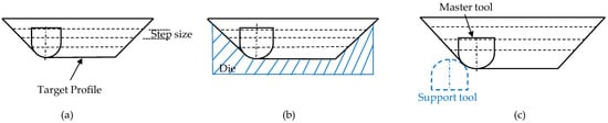
2. Process Mechanism of DSIF

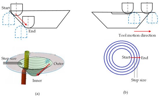
2.1. Toolpath Generation for DSIF Process

The toolpath strategy categorizes DSIF into conventional-DSIF (DSIF) and accumulative-DSIF (ADSIF). In DSIF, the tools’ downward movement from the outer toward the inner annulus obtains the required profile. The part profile is obtained from the synchronized movement of tools via in-plane and normal to the in-plane direction such as in the SPIF process (Figure 2a). In ADSIF (Figure 2b), both tools move horizontally outward to form the components. The already processed inner material moves downward by rigid body motion [20,21]. 
Figure 2. Schematics of (a) DISF (b) ADSIF toolpath.

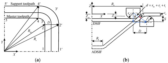
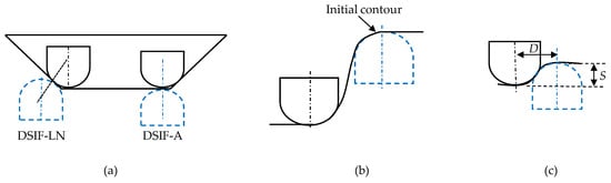
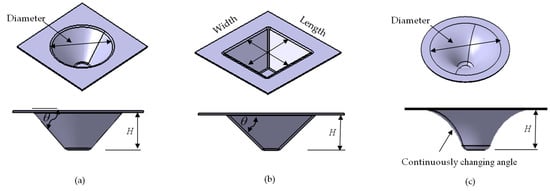
Both for DSIF and ADSIF, the master tool coordinates (Xm,Ym and Zm) are obtained from the CAD/CAM software. The position of the support tool in DSIF and ADSIF was defined via two parameters D and S (Figure 3) by utilizing Equations (1) and (2).

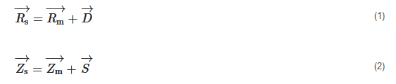
where D is the distance between the axis of the two tools in the XY plane; S is the vertical distance between the bottom of the sheet and the tip of the support tool in the XZ plane; Zm and Zs are the master and support tool position in the XZ plane; Rm and Rs is the master and support tool position in the XY plane. In DSIF, parameters D and S are determined by utilizing the sine law and the normal tool configuration. From Figure 3b, it is evident that D=d⋅sinθ, and S=rm+rs−d⋅cosθ+to, where rm and rs are the master and support tool radius, θ is the local wall angle, and to is the original sheet thickness. The D and S should change continuously as part height increases due to the dependence on the sheet thickness at the contact point (ti) (Figure 3b). Due to sine law limitations, they are mostly held constant after the initial setup at the first contour.

Figure 3. DSIF and ADSIF toolpath generation strategy (reprinted with permission from S. Ullah et al. [22]). (a) top view (b) side view.
In DSIF, a flexible support tool is used, which can change its position regarding the master tool. Based on this flexibility, many tool configurations are derived. The two tool configurations based on local support to the master tools are: aligned (DSIF-A) and normal (DSIF-LN) (Figure 4a). In DSIF-A, the tool axes are parallel and on the same line. In the DSIF-LN configuration, the tool-tip centers are along the local normal at the contact point of the sheet [23]. Due to the support tool’s ineffective utilization at the component opening, the DSIF-A configuration is not frequently used. Therefore, in this work, DSIF-L will refer to DSIF-LN unless otherwise specified. Two other tool configurations based on the support tool locations are DSIF-L and DSIF-P (Figure 4a,b). In DSIF-P, the support tool moves at the part opening to act as a backing plate. It does not take part in the actual forming operation [24]. The support tool coordinates remain fixed at the initial contour, whereas the master tool coordinates are according to the part profile. In ADSIF, Equations (1) and (2) can acquire the support tool coordinates. However, in most cases in the previous studies, the support tool position is determined based on adjusting the parameters D and S
values iteratively with respect to the master tool (Figure 4c) [21,25].
Figure 4. (a) Schematics of normal and aligned tool configurations in DSIF-L (b) DSIF-P (c) ADSIF.
Due to DSIF process flexibility, new toolpaths such as mixed-DSIF (MDSIF), multi-stage DSIF, and hybrid DSIF were derived. MDSIF is the combination of ADSIF and DSIF. In multi-stage, the components are formed in several stages. Hybrid DSIF (where the heat source is also incorporated) is executed for geometric accuracy and formability improvement of hard-to-form metals. In a nutshell, the flexible DSIF process can use different toolpath strategies to form components.

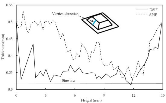
2.2. The Role of Thickness Variations in DSIF Toolpath

In ISF, the final sheet thickness is usually calculated by sine law, (tf=to⋅sin(90−θ)) where tf: the final sheet thickness after deformation, to: the original sheet thickness, and θ: local wall angle. The local wall angle can be used to find the thickness at any point in the component of complex geometry. The ti (instant sheet thickness) in Figure 3b is not necessarily the sheet thickness predicted by sine law. This difference in ti from the sheet thickness indicated by sine law at different forming heights affects the support tool–sheet contacts. It is due to differences in calculated and actual D and S values. Malhotra et al. [26] initially reported this shortcoming in the sine law while forming the 65° cone. Sine law was used to regulate the gap between the tools. After a certain forming height, the support tool disengaged from the sheet. The process degenerated to SPIF, resulting in early fracture. Squeezing was utilized to improve the support tool–sheet contact; however, it did not ensure accuracy.

According to Moser et al. [27], successfully maintaining contact between tools and the sheet can improve sheet thickness distribution, increase material formability, and reduce the early fracture. In their view, factors responsible for the tool–sheet contact lost problem were an inaccurate prediction of thickness predicted by sine law, tool misalignment, and ignoring machine compliance effect. They concentrated on sheet thickness problems in their work and the spring back and machine compliance for the shamrock section with a 65° wall angle. Preliminary work in LS-DYNA determined the thickness profile. The D and S adjustments were according to the projected thickness of the sheet. The sheet thickness distribution was decoupled from wall angle and was associated with in-plane curvature and part height. The gap determined by sine law leads to disengagement of support tools, whereas the new approach works effectively. However, their work was specific to the shamrock part. For 90° wall angle, the sheet thickness becomes zero according to the sine law. Moser et al. [28] modified the sine law for the vertical wall angle component to prevent the tool gap from approaching zero.
Otsu et al. [29] compared the sheet thickness distribution for SPIF and DSIF-L. SPIF does not observe the sheet thickness variation at the part opening due to global bending effects. In DSIF, the variation in sheet thickness is started from the beginning (Figure 5). It was attributed to the strong restraint on the sheet by the tools from both sides. The wall thickness predicted by sine law was 0.32 mm. As evident from Figure 5, the thickness acquired with DSIF-L is relatively closer to the sine law prediction along the complete section; however, it does not match the thickness predicted by the sine law.
Figure 5. Distributions of sheet thickness in the vertical direction (reprinted with permission from Otsu et al. [29], Copyright 2018 Elsevier).
Bin Lu et al. [30] compared the DSIF-L and DSIF-P strategies for wall thickness variation in a 0.5 mm sheet. No significant difference was observed in the sheet thickness acquired with DSIF-P (0.463 mm) and DSIF-L (0.461 mm). The slight difference for the DSIF-L, being on the lower side, was attributed to the local squeezing of the sheet. Malhotra et al. [31] compared the ADSIF and SPIF and observed that the sheet thickness acquired with ADSIF was on the lower side. The sheet thickness variation is minimum across the complete part height compared to SPIF. Zhang et al. [32] compared the sheet thickness variation in DSIF-L, ADSIF, and MDSIF. The thickness profile of the DSIF-L deviates relatively more from the sine law prediction, whereas the ADSIF and MDSIF processes were reported to be closer to the sine law curve.
The sheet thickness variation is the main study in SPIF [33,34,35,36]. In DSIF, the sheet thickness variation is relatively better than in SPIF; however, the unpredicted thickness variation leads to ineffective tool–sheet contact, which degenerates the process to SPIF. Formability and deformation can be improved by avoiding support tool–sheet lost contact.

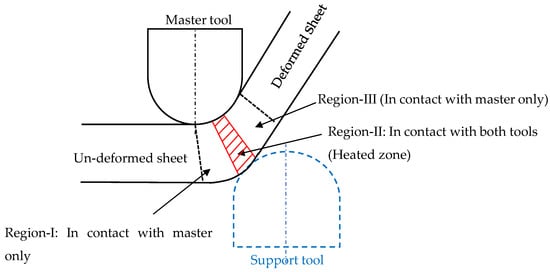
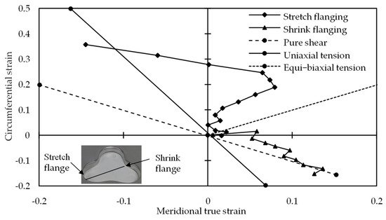
2.3. Deformation and Fracture Mechanism in DSIF

Because of the increased compressive force provided by the support tool, it is usually assumed that the DSIF has higher formability than the SPIF. The support tool must maintain constant contact with the sheet to benefit from the compressive force. Meier et al. [37] utilized the support tool with 300 N force in the DSIF-L orientation to ensure the support tool–sheet contact and reported a wall angle of 72° for the hyperboloid component. An earlier study in SPIF could not acquire a wall angle of more than 65°. The support tool force helped in increasing the formability by 12.5%. According to Malhotra et al. [26], the DSIF toolpath improves precision and formability by stabilizing distortion within a narrow zone surrounding the tool’s contact site. B. Lu et al. [38] observed the evolution of fracture depth in AA7075-T6 with varying squeezing forces. For squeezing force less than 240 N, there is no significant change in the fracture depth, and the tool squeezing does not make any apparent effect. Squeezing force from 240 to 480 N increases the formability from 20 to 30 mm. Increasing the squeezing force to 560 N harms the fracture depth (Figure 6). It was analytically proved by a sudden drop in stress triaxiality point for stresses in the 240–480 N range. As illustrated in Figure 7, the forces in this range were observed for various support tool adjustments (without tool shifting is DSIF-L orientation, whereas with tool shift is support tool adjustment in the middle position between DSIF-L and DSIF-A). The increasing squeezing force with tool shift adjustments positively impacts formability improvement than the other tool adjustments. The fracture occurred in both cases in the sheet region, which was in contact with a master tool, emphasizing the relevance of the support tool in delaying the fracture. Under excessive-high contact pressure and high friction, the tools may “clamp” and “stretch” the sheet in the moving direction, leading to high tensile stress conditions around the deformation zone and early failure of the sheet.
Figure 6. Variation for forming depth under different supporting forces (reprinted with permission from B. Lu et al. [38], Copyright 2015 Elsevier).
Figure 7. Influence of slave tool shift on DSIF formability (reprinted with permission from B. Lu et al. [38], Copyright 2015 Elsevier).
Valoppi et al. [39] utilized the analytical model proposed by B. Lu et al. [38] to investigate the fracture characteristics of Ti6Al4V sheets in the electric-assisted DSIF (E-DSIF) process. The deformation region was divided into three zones (Region-I, II, and III) to investigate the relationship between the E-DSIF fracture surfaces and the stress state (Figure 8). Region-I and III experience meridional tensile stresses, and Region-II experience compressive stresses due to support tool squeezing. They reported that the outer Region-III is more susceptible to fracture due to reduced radial thickness, local bending, and more circumferential stress due to tool movement in that direction. It was further exaggerated by current, which increased through the thickness-shear too.
Figure 8. Deformation zones in the E-DSIF process.
Zhang et al. [40] analyzed the strain evolution for clover flange (Figure 9). Increased circumferential and reduced meridional strain improved formability in stretch flanging. Meridional tensile and the localized deformation mode improved the formability of shrink flanging. With meridional tensile and circumferential compressive, the risk of wrinkling is minimized. With this combination, the strain state was close to pure shear, which was stable for sheet metal forming. Moser et al. [41] investigated the shrink and a stretch portion of the shamrock part. The shrink portion experiences a mixture of negative strain (compressive force) and stretching. It resulted in an enlarged contact region of the support tool with the sheet, which helped effective tool–sheet contact. The support tool–sheet contact was not intact in the stretch flange as the formed height increased. It leads to a loss in squeezing, and the process becomes degenerated to SPIF having less geometric precision and formability.
Figure 9. Strain evolutions on X-axis cross-section (reprinted with permission from Zhang et al. [40], Copyright 2018 Elsevier).
In ADSIF, local bending of the sheet around the tool, a squeezing action due to the support tool, and shear perpendicular to and parallel to the tool motion improved formability [20]. Malhotra et al. [42] have shown that raising hydrostatic pressure and increasing through-the-thickness shear reduces the potential for sheet metal to fracture during the forming process. The higher hydrostatic pressure in ADSIF due to the support tool’s effective contact with the sheet prevents shear bands from forming. If shear bands do form, the compressive load state stops voids from expanding further, preventing material fracture. Davarpanah et al. [43] hypothesized that the support tool’s continuous contact with the sheet improved formability.
In a nutshell, the successful contact of the support tool with the sheet increases the formability and delays the fracture, as evident in the previous studies. The unpredicted thickness variation during the DSIF process, on the other hand, leads to incorrect tool gap adjustment, which in most cases degenerates the DSIF to SPIF and early fracture. It has relation to component geometric precision and is examined in the next section.

3. Accuracy Improvement in DSIF Process

The required and form profile difference is considered a geometric error [44]. In most cases, the required geometric accuracy for commercial parts is ±1 mm. In some cases, it becomes much stricter up to ±0.2 mm. The reported accuracy in ISF is still struggling to achieve these values [16]. There are mainly three regions where a geometric error occurs in the form part: (a) sheet bending between the sheet support at the periphery and current tool position (b) in-accuracy at the wall region: The error source in this region is due to (i) tool and machine compliance (ii) in-process springback (iii) post-springback after part un-clamping from the fixture. These errors are considered a challenge, and researchers have utilized different techniques to overcome the root cause of these errors (c). The unwanted curvature at the final product base (the pillow effect) is seen below (Figure 10).
Figure 10. (a) Geometric error (reprinted with permission from Micari et al. [44], Copyright 2007 Elsevier). (b) Wall region error detail.
Cone, pyramid, and funnel are some of the benchmark shapes trialed by researchers in ISF (Figure 11). Besides, based on the specific challenge, some researchers have worked on other profiles such as fish fin, shamrock, ellipsoidal, etc. For pyramid, length and width at the part opening are the same unless otherwise specified. Therefore, in (Table 1, Table 2 and Table 3), in the part size column, O is used to represent both the length and width of the pyramid, whereas, for cone and funnel, it is the diameter. In the funnel, the wall angle changes continuously. It is minimum at the part opening and increases along with the part height. The part errors in this study, in most cases, represent the under-forming part. Errors defined with the plus-minus sign are for over and under-forming parts.
Figure 11. ISF benchmark shape (a) cone (b) pyramid (c) funnel.
Table 1. Accuracy improvements based on tool-path compensation.

Method

Part Type

Error (mm)

Part Size (mm)

(O × H × θ)

Thick (mm)

Material

Cause-and-Effect

Researchers

Springback and machine compliances

cone

±0.25

100 × 40 × 53°

0.8

AA99.5

Springback, sine law-undersize, compliance- oversize

Meier et al. (2009)

Squeezing (1.0,0.9,0.85)

cone

improved

130 × 36 × 65°

1.5

AA5182

Sine law-support tool lost contact

Malhotra et al. (2011)

Tool gap correction

shamrock

NR

110 × 31.2 × 65°

1.0

AA5754

Modified sine law-specific to shamrock

Moser et al. (2016)

Support tool force control

cone

1.0

45 × 16 × 40°

0.5

AA2024-T3

Complicated- Implementation issue

Ren et al. (2018)

funnel

NR

45 × 22 × 65°

1.0

AA5754-O

In-situ springback

cone

0.8

70 × 22 × 45°

0.5

AA2024-T3

Simulation based-time consuming

Ren et al. (2019)

pyramid

0.2

80 × 22 × 45°

1.0

AA5754-O

Tool and sheet deflection (small part)

cone

0.40

78.6 × 20 × 60°

0.88

AA5052-O

Empirical formula-limited to small parts

Lingam et al. (2015, 2016)

funnel

0.46

80 × 22.5 × 60°

Tool and sheet deflection (large part)

Varying wall component

1.25

260 × 72 × 60°

0.8

AA8011

No machine compliance- support tool lost contact

Praveen et al. (2020)

Elliptical free-form

1.52

640 × 110 × 55°

Machine, tool, and sheet deflection (large part)

Varying wall component

0.62

260 × 72 × 60°

Empirical formula: trialed for AA8011 only with a thin sheet

Konka et al. (2020)

Elliptical free-form

0.93

640 × 110× 55°

Incremental springback accommodation (D-DSIF)

Pyramid

0.33

0.57

45 × 15 × 40°

100 × 30 × 45°

1.0

AA7075

DC-04

Implementations of the second stage should be based on the formula

S. Ullah et al. (2021)

Table 2. Accuracy improvements based on tool-path adaptation.

Method

Part Type

Error (mm)

Part Size (mm) (O × H × θ)

Thick (mm)

Material

Cause and Effect

Researchers

DSIF-L

DSIF-P

DSIF-L

DSIF-P

Free-form

1.0

NR

NR

Al Mn 99.8

Trial based and sine law-time consuming

Meier et al. (2011)

2.5

Skull

<5.0

<(120 × 25)

0.5

Grade-1

Titanium

Insufficient support-increase in error

Bin Lu et al. (2015

5.0

ADSIF

Cone

0.49

45 × 14 × 40°

0.5

AA2024-T3

Low step size, trial based-time consuming

Malhotra et al. (2012)

45 × 17 × 50°

MDSIF

(ASIF+DSIF)

Pyramid with pocket

<0.49

45 × 15 × varied

0.5

AA2024-T3

Based on ADSIF-time consuming

Zhang et al. (2015)

Reverse bending

Ellipsoidal

±0.25

Major:112 × 21 × 41.1°

Minor:102 × 21 × 44.8°

1.0

AA7075

Over bending-precision degradation

Wang et al. (2018)

Squeezing

0.4

Ineffective-springback reduction

Automatic feature recognition

Conical profile with an inclined hump

0.3

80 × 17 × NR

0.88

AA5052

Lingam and Ndip-Agbor strategy recommended the sequence in the opposite direction

Lingam et al. (2017)

pyramid with an inclined base and a protrusion

0.25

80 × 17 × 45°

Multiple features with Z-based slicing

Freeform

1.5

<(80 × 18)

1.0

AA5754-O

Ndip-Agbor et al. (2018)

Tool-path adaptation based on STL model

Bidirectional protruding feature

3.2

<(200 × 25)

0.6

AA1060

Springback: precision degradation

Zhu et al. (2019b)

Table 3. Accuracy improvement based on the heat-assisted process.

Method

Part Type

Error (mm)

Part Size (O × H × θ) (O and H in mm)

Thickness (mm)

Material

Researchers

Direct resistance heating

Cone

1.0

NR

0.8

DX54D

Meier and Magnus (2013)

High-density pulse

Pyramid

NR

NR × 25 × 45°

NR

Titanium

Asghar and Reddy (2013)

HE-DSIF

Cone

1.0

80 × 25 × 45°

1.41

AZ3B1

Xu et al. (2016)

E-DSIF

2.2

E-SPIF

>3.0

E-MDSIF

Free-form

1.98

Figure 19

0.5

Ti6Al4V

Valoppi et al. (2016)

E-ADSIF

8.0

Without current

15.42

The main focus of the early research was to validate the process’s capability to form complex parts. A robot having a 15 kg payload capacity was utilized by Meier et al. [24] to form a cone from the AA 99.5 sheet. The formed part in some regions was undersized due to material springback and oversized in others due to the machine compliance. The part accuracy became homogeneous with the heavy-duty (360 kg payload capacity) robot, as the machine compliances were reduced. Wang et al. [45] formed a complex part having curvature on both sides of the sheet without changing the setup. The machine used was a milling machine. SPIF and DSIF processes were compared for geometric accuracy by forming a sphere on the same blank. DSIF enhanced the accuracy at the part lower region, whereas SPIF performed better at the part opening area than DSIF. The reason was that a sphere was formed first with DSIF, which increased the sheet stiffness. SPIF took advantage of this increase in sheet stiffness for precision improvement at the component opening. Due to the C-frame structure utilized in their work, they were able to form parts with the wall angles in a certain range. While studying the effect of the tool gap for formability enhancement, Wang et al. [46] recommended 0.8–0.9 times the thickness of the original sheet. The machine used was a lathe machine, which can mainly be used for symmetric shapes. Based on these preliminary works, DSIF comes to attention due to its adaptability with a different setup and complex part flexibly forming capability.

This entry is adapted from the peer-reviewed paper 10.3390/met12010103

This entry is offline, you can click here to edit this entry!