 +1 credit
| Version | Summary | Created by | Modification | Content Size | Created at | Operation |
|---|---|---|---|---|---|---|
| 1 | sattar Ullah | -- | 3997 | 2022-04-28 07:05:30 | | | |
| 2 | Peter Tang | -57 word(s) | 3940 | 2022-04-28 07:50:41 | | | | |
| 3 | Peter Tang | Meta information modification | 3940 | 2022-05-05 07:43:19 | | |
Video Upload Options
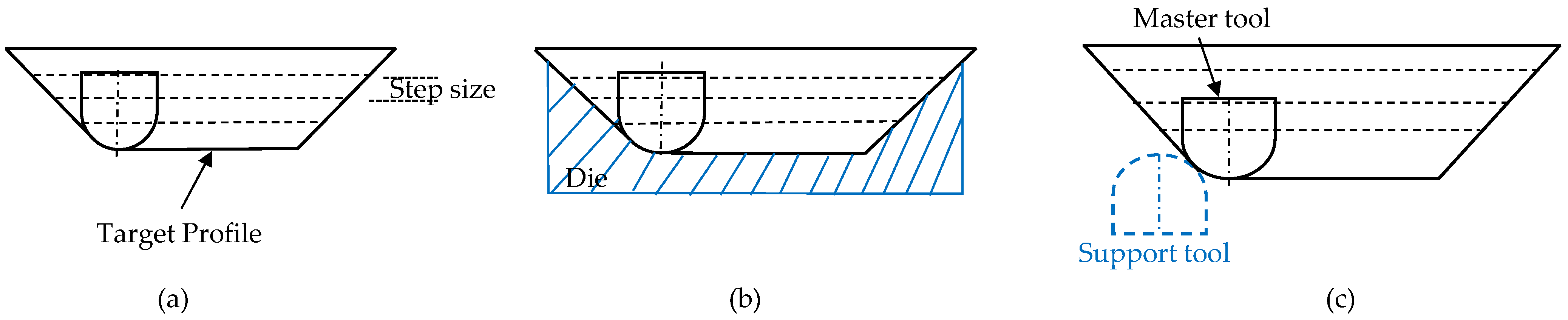
Low geometric accuracy is one of the main limitations in double-sided incremental forming (DSIF) with a rough surface finish, long forming time, and excessive sheet thinning. The lost contact between the support tool and the sheet is considered the main reason for the geometric error. Toolpath compensations strategies improve geometric precision without adding extra tooling to the setup. It relies on formulas, simulation, and algorithm-based studies to enhance the part accuracy. Toolpath adaptation improves the part accuracy by adding additional equipment such as pneumatically or spring-loaded support tools or changing the conventional toolpath sequence such as accumulative-DSIF (ADSIF) and its variants. It also includes forming multi-region parts with various arrangements. Toolpath adaptation mostly requires experimental trial-and-error experiments to adjust parameters to obtain the desired shape with precision. Material redistribution strategies are effective for high-wall-angle parts.
1. Introduction
2. Process Mechanism of DSIF
2.1. Toolpath Generation for DSIF Process
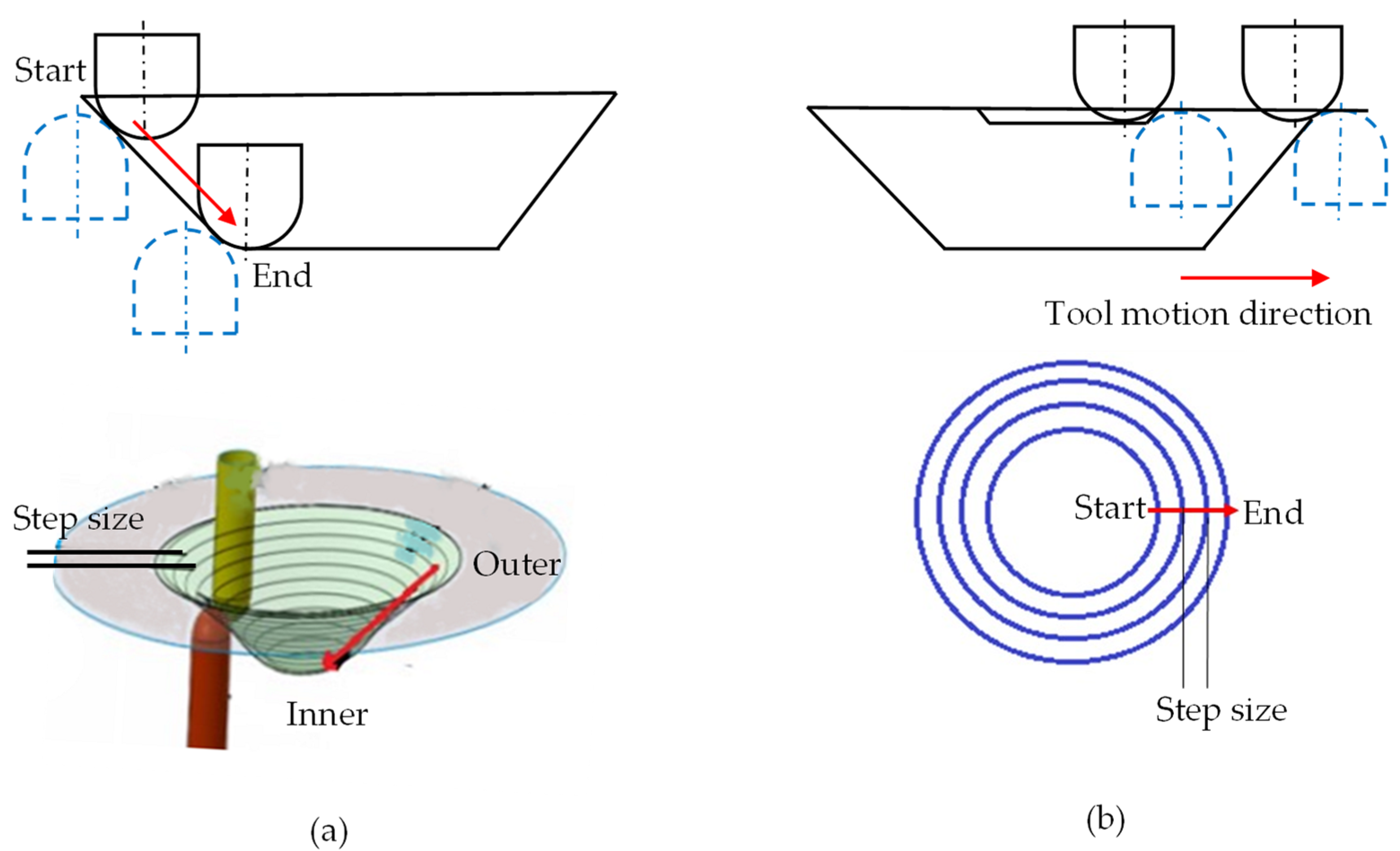
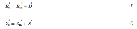
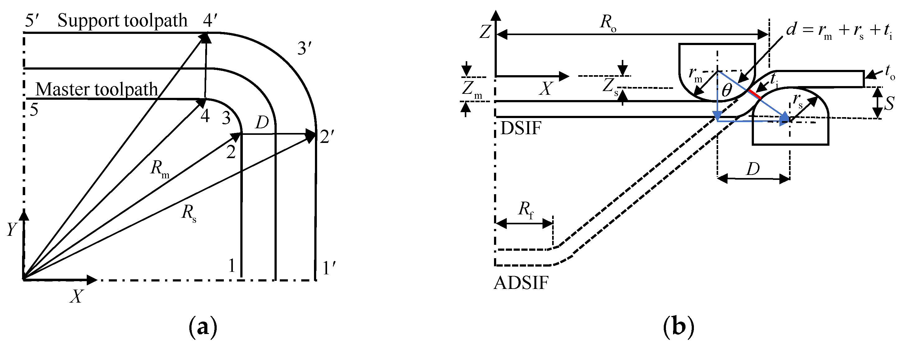
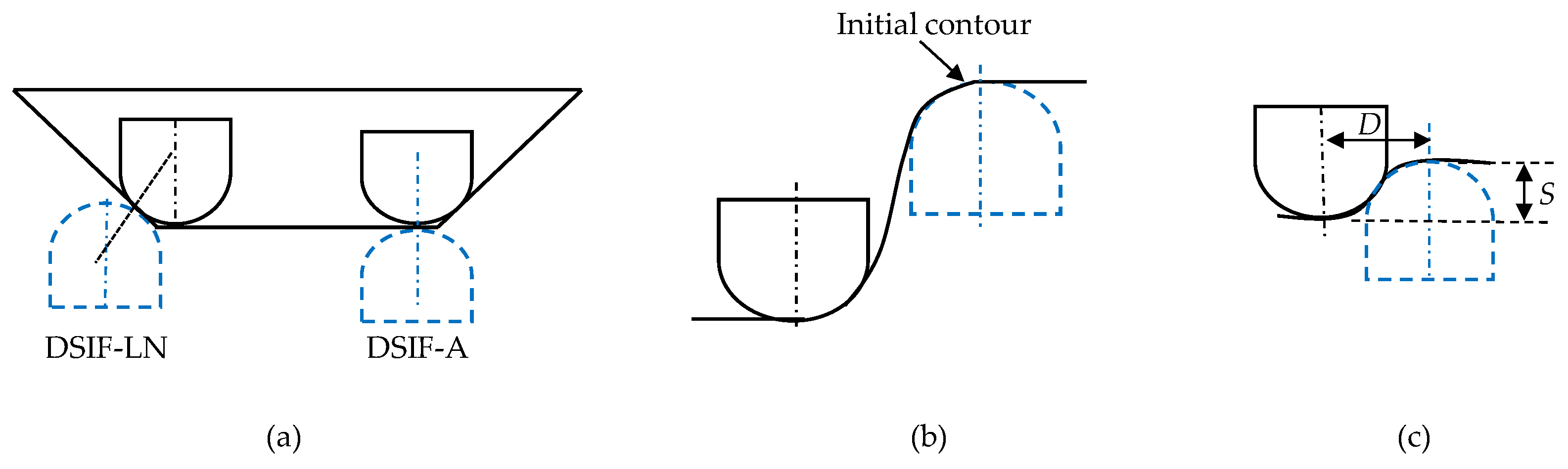
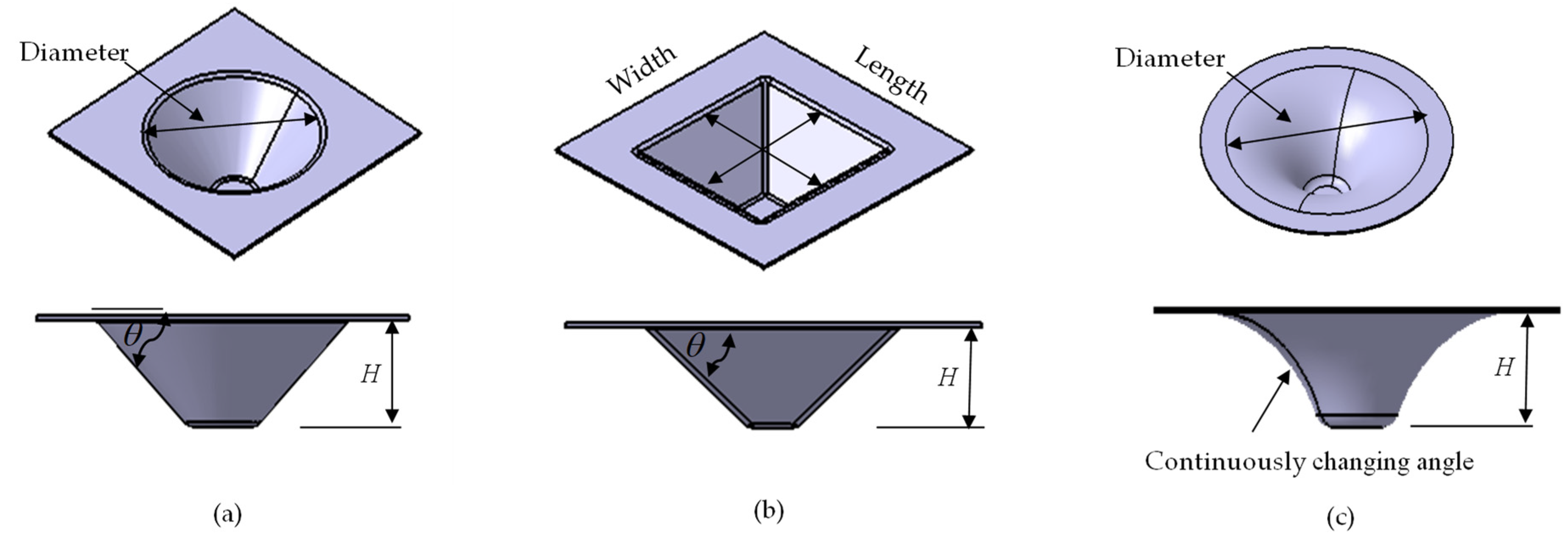
Both for DSIF and ADSIF, the master tool coordinates (Xm,Ym and Zm) are obtained from the CAD/CAM software. The position of the support tool in DSIF and ADSIF was defined via two parameters D and S (Figure 3) by utilizing Equations (1) and (2).
where D is the distance between the axis of the two tools in the XY plane; S is the vertical distance between the bottom of the sheet and the tip of the support tool in the XZ plane; Zm and Zs are the master and support tool position in the XZ plane; Rm and Rs is the master and support tool position in the XY plane. In DSIF, parameters D and S are determined by utilizing the sine law and the normal tool configuration. From Figure 3b, it is evident that D=d⋅sinθ, and S=rm+rs−d⋅cosθ+to, where rm and rs are the master and support tool radius, θ is the local wall angle, and to is the original sheet thickness. The D and S should change continuously as part height increases due to the dependence on the sheet thickness at the contact point (ti) (Figure 3b). Due to sine law limitations, they are mostly held constant after the initial setup at the first contour.
2.2. The Role of Thickness Variations in DSIF Toolpath
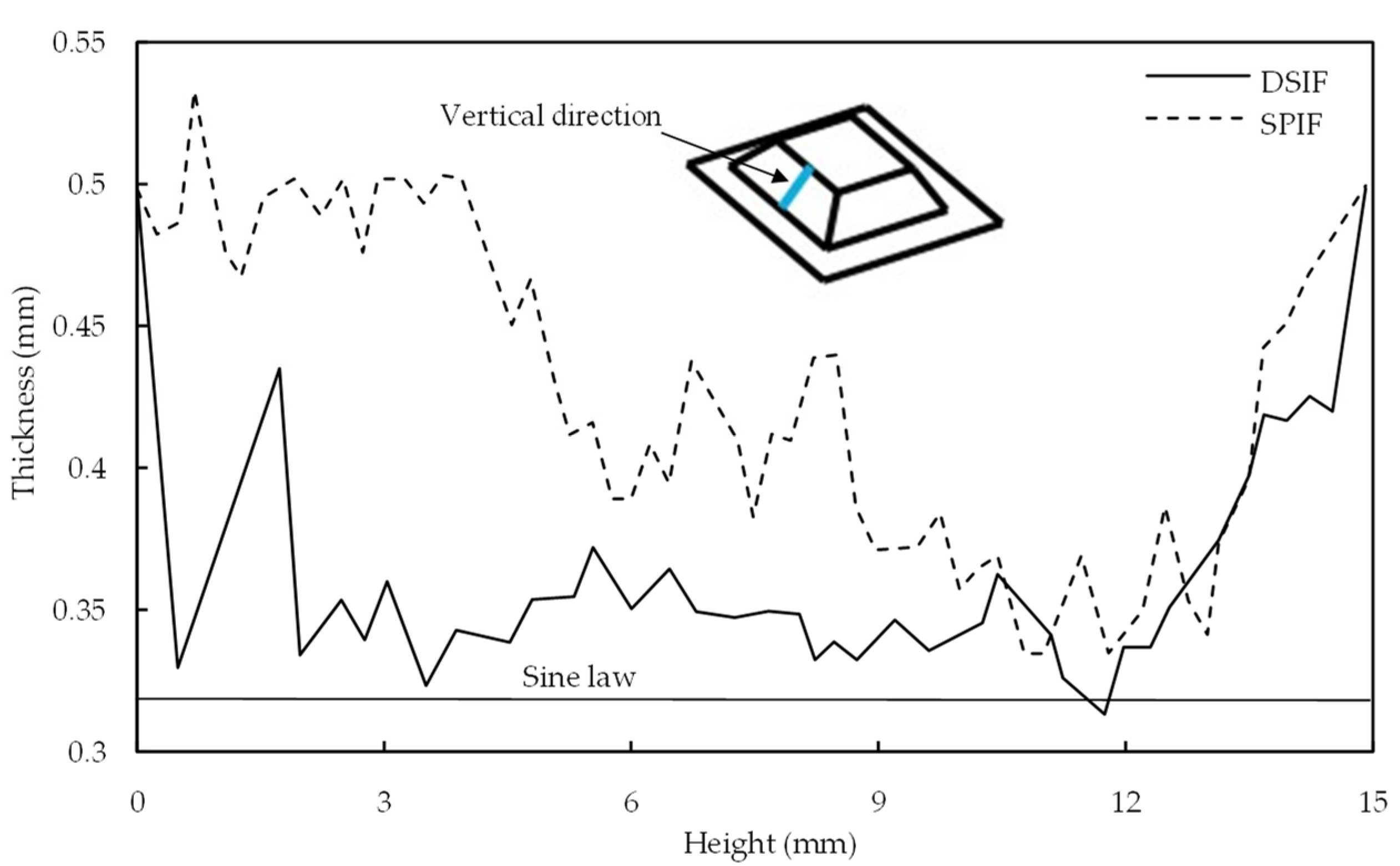
In ISF, the final sheet thickness is usually calculated by sine law, (tf=to⋅sin(90−θ)) where tf: the final sheet thickness after deformation, to: the original sheet thickness, and θ: local wall angle. The local wall angle can be used to find the thickness at any point in the component of complex geometry. The ti (instant sheet thickness) in Figure 3b is not necessarily the sheet thickness predicted by sine law. This difference in ti from the sheet thickness indicated by sine law at different forming heights affects the support tool–sheet contacts. It is due to differences in calculated and actual D and S values. Malhotra et al. [26] initially reported this shortcoming in the sine law while forming the 65° cone. Sine law was used to regulate the gap between the tools. After a certain forming height, the support tool disengaged from the sheet. The process degenerated to SPIF, resulting in early fracture. Squeezing was utilized to improve the support tool–sheet contact; however, it did not ensure accuracy.
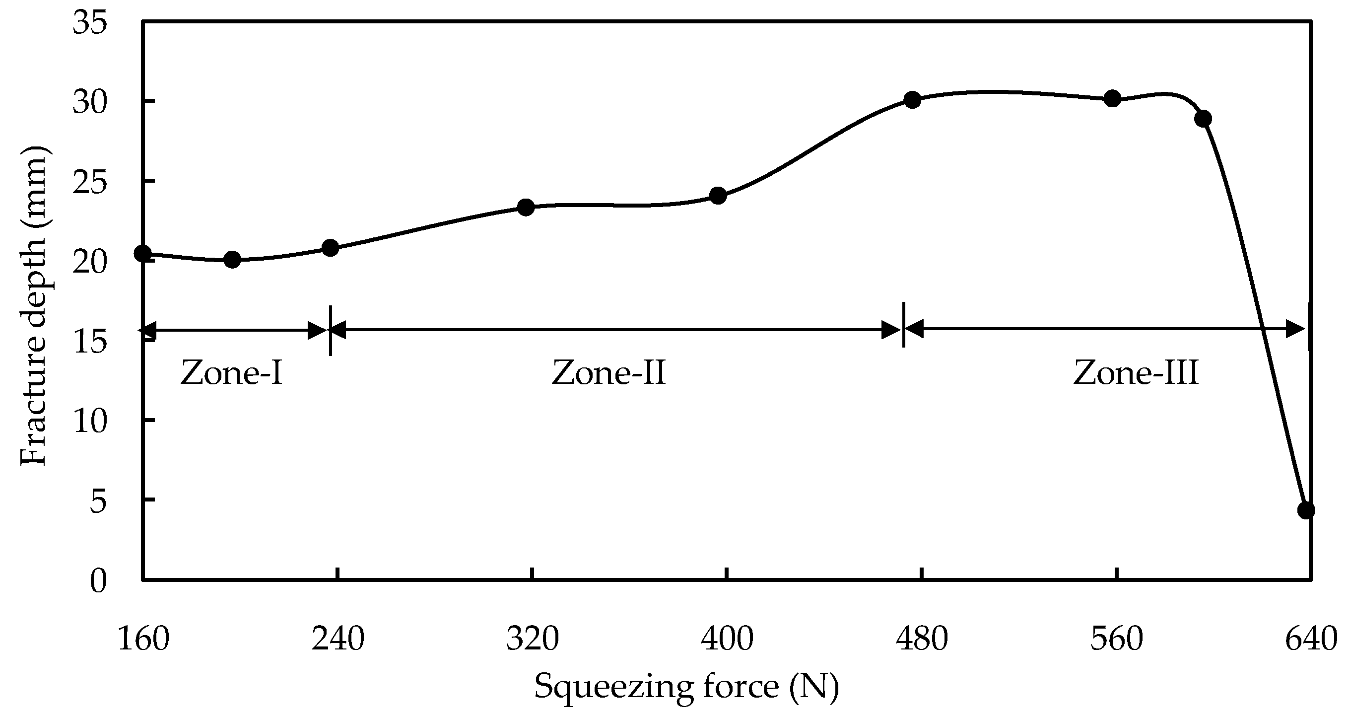
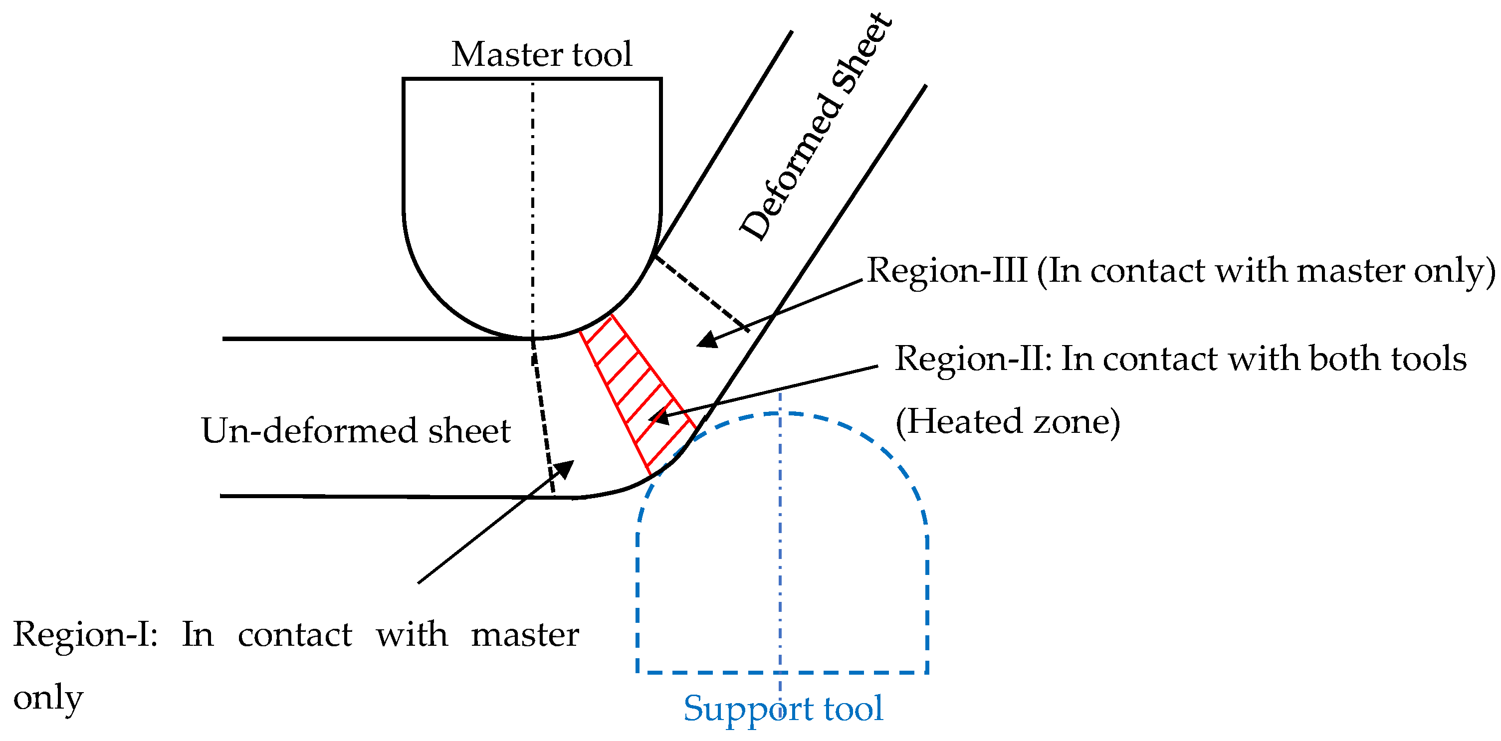
2.3. Deformation and Fracture Mechanism in DSIF
3. Accuracy Improvement in DSIF Process
|
Method |
Part Type |
Error (mm) |
Part Size (mm) (O × H × θ) |
Thick (mm) |
Material |
Cause-and-Effect |
Researchers |
|---|---|---|---|---|---|---|---|
|
Springback and machine compliances |
cone |
±0.25 |
100 × 40 × 53° |
0.8 |
AA99.5 |
Springback, sine law-undersize, compliance- oversize |
Meier et al. (2009) |
|
Squeezing (1.0,0.9,0.85) |
cone |
improved |
130 × 36 × 65° |
1.5 |
AA5182 |
Sine law-support tool lost contact |
Malhotra et al. (2011) |
|
Tool gap correction |
shamrock |
NR |
110 × 31.2 × 65° |
1.0 |
AA5754 |
Modified sine law-specific to shamrock |
Moser et al. (2016) |
|
Support tool force control |
cone |
1.0 |
45 × 16 × 40° |
0.5 |
AA2024-T3 |
Complicated- Implementation issue |
Ren et al. (2018) |
|
funnel |
NR |
45 × 22 × 65° |
1.0 |
AA5754-O |
|||
|
In-situ springback |
cone |
0.8 |
70 × 22 × 45° |
0.5 |
AA2024-T3 |
Simulation based-time consuming |
Ren et al. (2019) |
|
pyramid |
0.2 |
80 × 22 × 45° |
1.0 |
AA5754-O |
|||
|
Tool and sheet deflection (small part) |
cone |
0.40 |
78.6 × 20 × 60° |
0.88 |
AA5052-O |
Empirical formula-limited to small parts |
Lingam et al. (2015, 2016) |
|
funnel |
0.46 |
80 × 22.5 × 60° |
|||||
|
Tool and sheet deflection (large part) |
Varying wall component |
1.25 |
260 × 72 × 60° |
0.8 |
AA8011 |
No machine compliance- support tool lost contact |
Praveen et al. (2020) |
|
Elliptical free-form |
1.52 |
640 × 110 × 55° |
|||||
|
Machine, tool, and sheet deflection (large part) |
Varying wall component |
0.62 |
260 × 72 × 60° |
Empirical formula: trialed for AA8011 only with a thin sheet |
Konka et al. (2020) |
||
|
Elliptical free-form |
0.93 |
640 × 110× 55° |
|||||
|
Incremental springback accommodation (D-DSIF) |
Pyramid |
0.33 0.57 |
45 × 15 × 40° 100 × 30 × 45° |
1.0 |
AA7075 DC-04 |
Implementations of the second stage should be based on the formula |
S. Ullah et al. (2021) |
|
Method |
Part Type |
Error (mm) |
Part Size (mm) (O × H × θ) |
Thick (mm) |
Material |
Cause and Effect |
Researchers |
|---|---|---|---|---|---|---|---|
|
DSIF-L DSIF-P DSIF-L DSIF-P |
Free-form |
1.0 |
NR |
NR |
Al Mn 99.8 |
Trial based and sine law-time consuming |
Meier et al. (2011) |
|
2.5 |
|||||||
|
Skull |
<5.0 |
<(120 × 25) |
0.5 |
Grade-1 Titanium |
Insufficient support-increase in error |
Bin Lu et al. (2015 |
|
|
5.0 |
|||||||
|
ADSIF |
Cone |
0.49 |
45 × 14 × 40° |
0.5 |
AA2024-T3 |
Low step size, trial based-time consuming |
Malhotra et al. (2012) |
|
45 × 17 × 50° |
|||||||
|
MDSIF (ASIF+DSIF) |
Pyramid with pocket |
<0.49 |
45 × 15 × varied |
0.5 |
AA2024-T3 |
Based on ADSIF-time consuming |
Zhang et al. (2015) |
|
Reverse bending |
Ellipsoidal |
±0.25 |
Major:112 × 21 × 41.1° Minor:102 × 21 × 44.8° |
1.0 |
AA7075 |
Over bending-precision degradation |
Wang et al. (2018) |
|
Squeezing |
0.4 |
Ineffective-springback reduction |
|||||
|
Automatic feature recognition |
Conical profile with an inclined hump |
0.3 |
80 × 17 × NR |
0.88 |
AA5052 |
Lingam and Ndip-Agbor strategy recommended the sequence in the opposite direction |
Lingam et al. (2017) |
|
pyramid with an inclined base and a protrusion |
0.25 |
80 × 17 × 45° |
|||||
|
Multiple features with Z-based slicing |
Freeform |
1.5 |
<(80 × 18) |
1.0 |
AA5754-O |
Ndip-Agbor et al. (2018) |
|
|
Tool-path adaptation based on STL model |
Bidirectional protruding feature |
3.2 |
<(200 × 25) |
0.6 |
AA1060 |
Springback: precision degradation |
Zhu et al. (2019b) |
|
Method |
Part Type |
Error (mm) |
Part Size (O × H × θ) (O and H in mm) |
Thickness (mm) |
Material |
Researchers |
|---|---|---|---|---|---|---|
|
Direct resistance heating |
Cone |
1.0 |
NR |
0.8 |
DX54D |
Meier and Magnus (2013) |
|
High-density pulse |
Pyramid |
NR |
NR × 25 × 45° |
NR |
Titanium |
Asghar and Reddy (2013) |
|
HE-DSIF |
Cone |
1.0 |
80 × 25 × 45° |
1.41 |
AZ3B1 |
Xu et al. (2016) |
|
E-DSIF |
2.2 |
|||||
|
E-SPIF |
>3.0 |
|||||
|
E-MDSIF |
Free-form |
1.98 |
Figure 19 |
0.5 |
Ti6Al4V |
Valoppi et al. (2016) |
|
E-ADSIF |
8.0 |
|||||
|
Without current |
15.42 |
References
- Duflou, J.R.; Habraken, A.-M.; Cao, J.; Malhotra, R.; Bambach, M.; Adams, D.; Vanhove, H.; Mohammadi, A.; Jeswiet, J. Single point incremental forming: State-of-the-art and prospects. Int. J. Mater. Form. 2017, 11, 743–773.
- Jeswiet, J.; Micari, F.; Hirt, G.; Bramley, A.; Duflou, J.; Allwood, J. Asymmetric Single Point Incremental Forming of Sheet Metal. CIRP Ann. 2005, 54, 88–114.
- Allwood, J.; Music, O.; Raithathna, A.; Duncan, S.R. Closed-loop feedback control of product properties in flexible metal forming processes with mobile tools. CIRP Ann. 2009, 58, 287–290.
- Allwood, J.M.; Braun, D.; Music, O. The effect of partially cut-out blanks on geometric accuracy in incremental sheet forming. J. Mater. Process. Technol. 2010, 210, 1501–1510.
- Nasulea, D.; Oancea, G. Achieving Accuracy Improvements for Single-Point Incremental Forming Process Using a Circumferential Hammering Tool. Metals 2021, 11, 482.
- Hussain, G.; Gao, L. A novel method to test the thinning limits of sheet metals in negative incremental forming. Int. J. Mach. Tools Manuf. 2007, 47, 419–435.
- Li, X.; Han, K.; Song, X.; Wang, H.; Li, D.; Li, Y.; Li, Q. Experimental and numerical investigation on surface quality for two-point incremental sheet forming with interpolator. Chin. J. Aeronaut. 2020, 33, 2794–2806.
- Wei, H.; Hussain, G.; Shi, X.; Isidore, B.B.L.; Alkahtani, M.; Abidi, M.H. Formability of Materials with Small Tools in Incremental Forming. Chin. J. Mech. Eng. 2020, 33, 1–9.
- Behera, A.K.; Verbert, J.; Lauwers, B.; Duflou, J.R. Tool path compensation strategies for single point incremental sheet forming using multivariate adaptive regression splines. Comput. Des. 2012, 45, 575–590.
- Lasunon, O.; Knight, W.A. Comparative investigation of single-point and double-point incremental sheet metal forming processes. Proc. Inst. Mech. Eng. Part B J. Eng. Manuf. 2007, 221, 1725–1732.
- Park, J.-J.; Kim, Y.-H. Fundamental studies on the incremental sheet metal forming technique. J. Mater. Process. Technol. 2003, 140, 447–453.
- Reddy, N.V.; Lingam, R.; Cao, J. Incremental metal forming processes in manufacturing. In Handbook of Manufacturing Engineering and Technology; Nee, A.Y.C., Ed.; Springer: London, UK, 2014; pp. 411–452.
- Behera, A.K.; de Sousa, R.A.; Ingarao, G.; Oleksik, V. Single point incremental forming: An assessment of the progress and technology trends from 2005 to 2015. J. Manuf. Process. 2017, 27, 37–62.
- Li, Y.; Chen, X.; Liu, Z.; Sun, J.; Li, F.; Li, J.; Zhao, G. A review on the recent development of incremental sheet-forming process. Int. J. Adv. Manuf. Technol. 2017, 92, 2439–2462.
- Ai, S.; Long, H. A review on material fracture mechanism in incremental sheet forming. Int. J. Adv. Manuf. Technol. 2019, 104, 33–61.
- Lu, H.; Liu, H.; Wang, C. Review on strategies for geometric accuracy improvement in incremental sheet forming. Int. J. Adv. Manuf. Technol. 2019, 102, 3381–3417.
- Peng, W.; Ou, H.; Becker, A. Double-Sided Incremental Forming: A Review. J. Manuf. Sci. Eng. 2019, 141, 1–42.
- Gohil, A.; Modi, B. Review of the effect of process parameters on performance measures in the incremental sheet forming process. Proc. Inst. Mech. Eng. Part B J. Eng. Manuf. 2020, 235, 303–332.
- Tomasz Trzepieci, N.; Oleksik, V.; Pepelnjak, T.; Mohammed Najm, S.; Paniti, I.; Kuntal, M. Emerging Trends in Single Point Incremental Sheet Forming of Lightweight Metals. Metals 2021, 11, 1188.
- Smith, J.; Malhotra, R.; Liu, W.K.; Cao, J. Deformation mechanics in single-point and accumulative double-sided incremental forming. Int. J. Adv. Manuf. Technol. 2013, 69, 1185–1201.
- Ren, H.; Moser, N.; Zhang, Z.; Ehmann, K.F.; Cao, J. Effects of tool deflection in accumulated double-sided incremental forming regarding part geometry. In Proceedings of the ASME 2016 11th International Manufacturing Science and Engineering Conference, Blacksburg, VA, USA, 27 June 2016; pp. 1–9.
- Ullah, S.; Li, X.; Xu, P.; Li, Y.; Han, K.; Li, D. A toolpath strategy for improving geometric accuracy in double-sided incremental sheet forming. Chin. J. Aeronaut. 2021.
- Lingam, R.; Bhattacharya, A.; Asghar, J.; Reddy, N.V. Compensations for tool path to enhance accuracy during double sided incremental forming. In Proceedings of the ASME 2015 International Manufacturing Science and Engineering Conference, Charlotte, NC, USA, 8–12 June 2015; pp. 1–8.
- Meier, H.; Smukala, V.; Dewald, O.; Zhang, J. Two Point Incremental Forming with Two Moving Forming Tools. Key Eng. Mater. 2007, 344, 599–605.
- Ndip-Agbor, E.; Smith, J.; Ren, H.; Jiang, Z.; Xu, J.; Moser, N.; Chen, W.; Xia, Z.C.; Cao, J. Optimization of relative tool position in accumulative double sided incremental forming using finite element analysis and model bias correction. Int. J. Mater. Form. 2015, 9, 371–382.
- Moser, N.; Zhang, Z.; Ren, H.; Zhang, H.; Shi, Y.; Ndip-Agbor, E.E.; Lu, B.; Chen, J.; Ehmann, K.F.; Cao, J. Effective forming strategy for double-sided incremental forming considering in-plane curvature and tool direction. CIRP Ann. 2016, 65, 265–268.
- Moser, N.; Ndip-Agbor, E.; Ren, H.Q.; Zhang, Z.X.; Ehmann, K.; Cao, J. Challenges and Process Strategies Concerning Multi-Pass Double Sided Incremental Forming. Key Eng. Mater. 2015, 651–653, 1122–1127.
- Otsu, M.; Nagai, S.-Y.; Miura, T.; Okada, M.; Yoshimura, H.; Matsumoto, R.; Muranaka, T. Forming accuracy improvement by double-side incremental forming. Procedia Manuf. 2018, 15, 1177–1183.
- Lu, B.; Xu, D.K.; Liu, R.Z.; Ou, H.A.; Long, H.; Chen, J. Cranial Reconstruction Using Double Side Incremental Forming. Key Eng. Mater. 2015, 639, 535–542.
- Malhotra, R.; Cao, J.; Beltran, M.; Xu, D.; Magargee, J.; Kiridena, V.; Xia, Z.C. Accumulative-DSIF strategy for enhancing process capabilities in incremental forming. CIRP Ann. 2012, 61, 251–254.
- Zhang, Z.; Ren, H.; Xu, R.; Moser, N.; Smith, J.; Ndip-Agbor, E.; Malhotra, R.; Xia, Z.C.; Ehmann, K.F.; Cao, J. A Mixed Double-Sided Incremental Forming Toolpath Strategy for Improved Geometric Accuracy. J. Manuf. Sci. Eng. 2015, 137, 051007.
- Choi, H.; Lee, C. A mathematical model to predict thickness distribution and formability of incremental forming combined with stretch forming. Robot. Comput. Manuf. 2018, 55, 164–172.
- Salem, E.; Shin, J.; Nath, M.; Banu, M.; Taub, A.I. Investigation of Thickness Variation in Single Point Incremental Forming. Procedia Manuf. 2016, 5, 828–837.
- Cao, T.; Lu, B.; Xu, D.; Zhang, H.; Chen, J.; Long, H.; Cao, J. An efficient method for thickness prediction in multi-pass incremental sheet forming. Int. J. Adv. Manuf. Technol. 2014, 77, 469–483.
- Mirnia, M.J.; Dariani, B.M.; Vanhove, H.; Duflou, J.R. An investigation into thickness distribution in single point incremental forming using sequential limit analysis. Int. J. Mater. Form. 2013, 7, 469–477.
- Meier, H.; Magnus, C.; Smukala, V. Impact of superimposed pressure on dieless incremental sheet metal forming with two moving tools. CIRP Ann. 2011, 60, 327–330.
- Malhotra, R.; Cao, J.; Ren, F.; Kiridena, V.; Xia, Z.C.; Reddy, N. Improvement of Geometric Accuracy in Incremental Forming by Using a Squeezing Toolpath Strategy with Two Forming Tools. J. Manuf. Sci. Eng. 2011, 133, 061019.
- Lu, B.; Fang, Y.; Xu, D.; Chen, J.; Ai, S.; Long, H.; Ou, H.; Cao, J. Investigation of material deformation mechanism in double side incremental sheet forming. Int. J. Mach. Tools Manuf. 2015, 93, 37–48.
- Valoppi, B.; Zhang, Z.; Deng, M.; Ghiotti, A.; Bruschi, S.; Ehmann, K.F.; Cao, J. On the Fracture Characterization in Double-Sided Incremental Forming of Ti6Al4V Sheets at Elevated Temperatures. Procedia Manuf. 2017, 10, 407–416.
- Zhang, H.; Zhang, Z.; Ren, H.; Cao, J.; Chen, J. Deformation mechanics and failure mode in stretch and shrink flanging by double-sided incremental forming. Int. J. Mech. Sci. 2018, 144, 216–222.
- Moser, N.; Zhang, Z.; Ren, H.; Ehmann, K.; Cao, J. An investigation into the mechanics of double-sided incremental forming using finite element methods. AIP Conf. Proc. 2016, 1769, 070021.
- Malhotra, R.; Xue, L.; Belytschko, T.; Cao, J. Mechanics of fracture in single point incremental forming. J. Mater. Process. Technol. 2012, 212, 1573–1590.
- Davarpanah, M.A.; Zhang, Z.; Bansal, S.; Cao, J.; Malhotra, R. Preliminary investigations on Double Sided Incremental Forming of thermoplastics. Manuf. Lett. 2016, 8, 21–26.
- Micari, F.; Ambrogio, G.; Filice, L. Shape and dimensional accuracy in Single Point Incremental Forming: State of the art and future trends. J. Mater. Process. Technol. 2007, 191, 390–395.
- Wang, Y.; Huang, Y.; Cao, J.; Reddy, N.V. Experimental study on a new method of double side incremental forming. In Proceedings of the ASME 2008 3rd International Manufacturing Science and Engineering Conference, Evanston, IL, USA, 7–10 October 2008.
- Wang, Y.; Wu, W.; Huang, Y.; Reddy, N.V.; Cao, J. Experimental and numerical analysis of double sided incremental forming. In Proceedings of the ASME 2009 International Manufacturing Science and Engineering Conference, West Lafayette, IN, USA, 4–7 October 2009.


