Computed tomography (CT) and Cardiac magnetic resonance (CMR) continue to advance the field of congenital cardiology by allowing for new and unique procedures not previously imagined. Enabling the interventionalist to enter the catheterization lab with a plan of attack expedites the procedure and has been shown to reduce procedural times and improve outcomes. Substantial advances in cross-sectional image resolution with a significant decrease in radiation exposure for cardiac CTs have led to more mainstream utilization. CMR has a unique ability to deliver real-time functional imaging in several views without exposing the patient to the detrimental effects of ionizing radiation. This can reduce procedural times in the interventional fluoroscopic suite to allow for more directed procedures.
1. Background
Historically, echocardiography has been the primary imaging tool used to help guide percutaneous interventional procedures in the congenital heart disease (CHD) population. Cross-sectional imaging is now emerging as an essential complement to patient selection and monitoring. With improvement in pre-procedural imaging, catheterization procedures are becoming more directed toward interventions and less diagnostic.
Cardiac computed tomography (CT) and cardiac magnetic resonance imaging (CMR) have made substantial improvements in sequencing, spatial resolution, and reduction in radiation exposure to the point where they are now routinely being employed to assist with pre-procedural planning. Meticulous pre-procedural planning has now led to significantly improved outcomes in the cardiac catheterization laboratory.
2. Cross-Sectional Imaging in Pediatric Interventional Cardiac Catheterization
2.1. Sinus Venosus Atrial Septal Defect (SVASD)
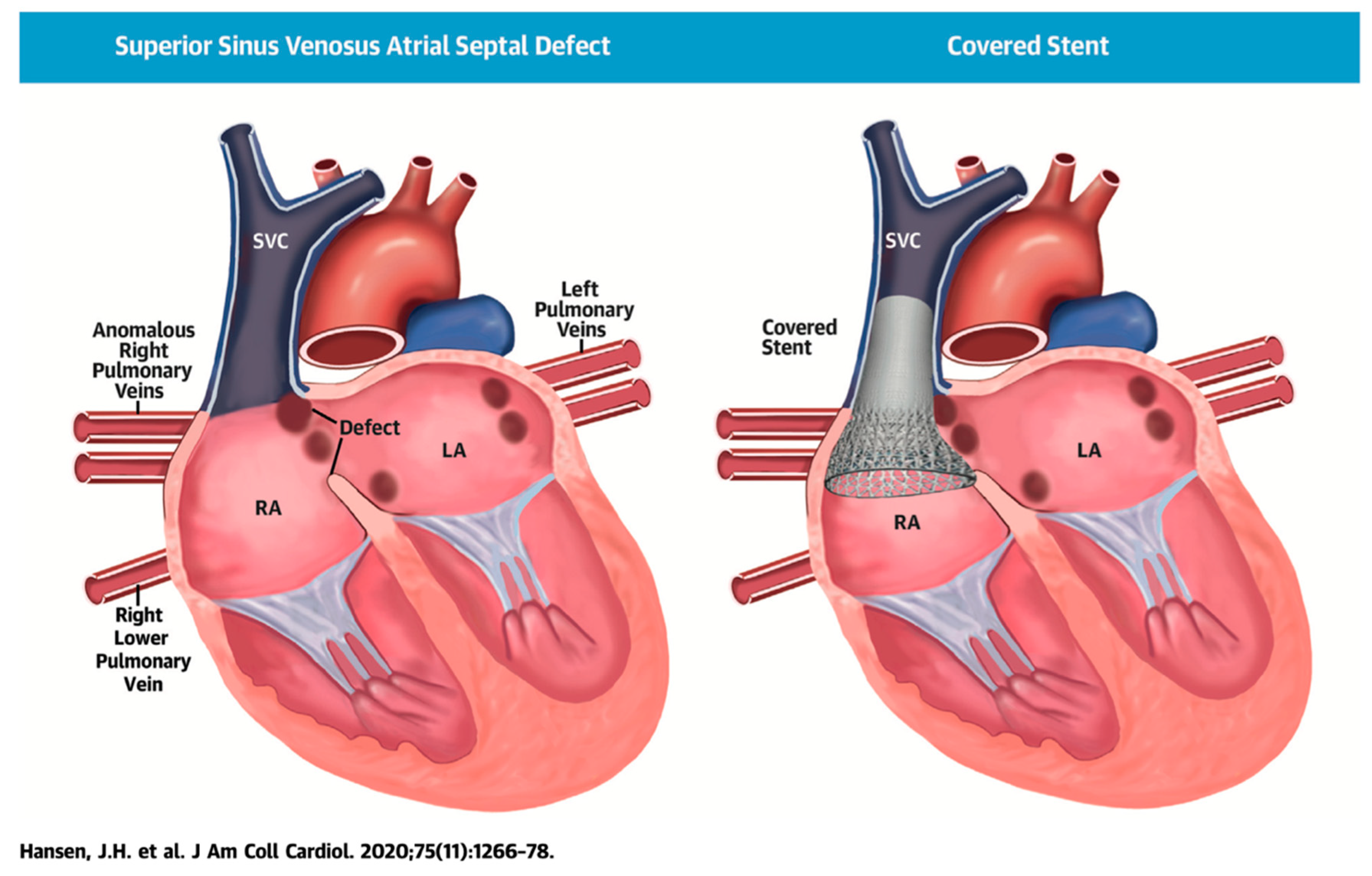
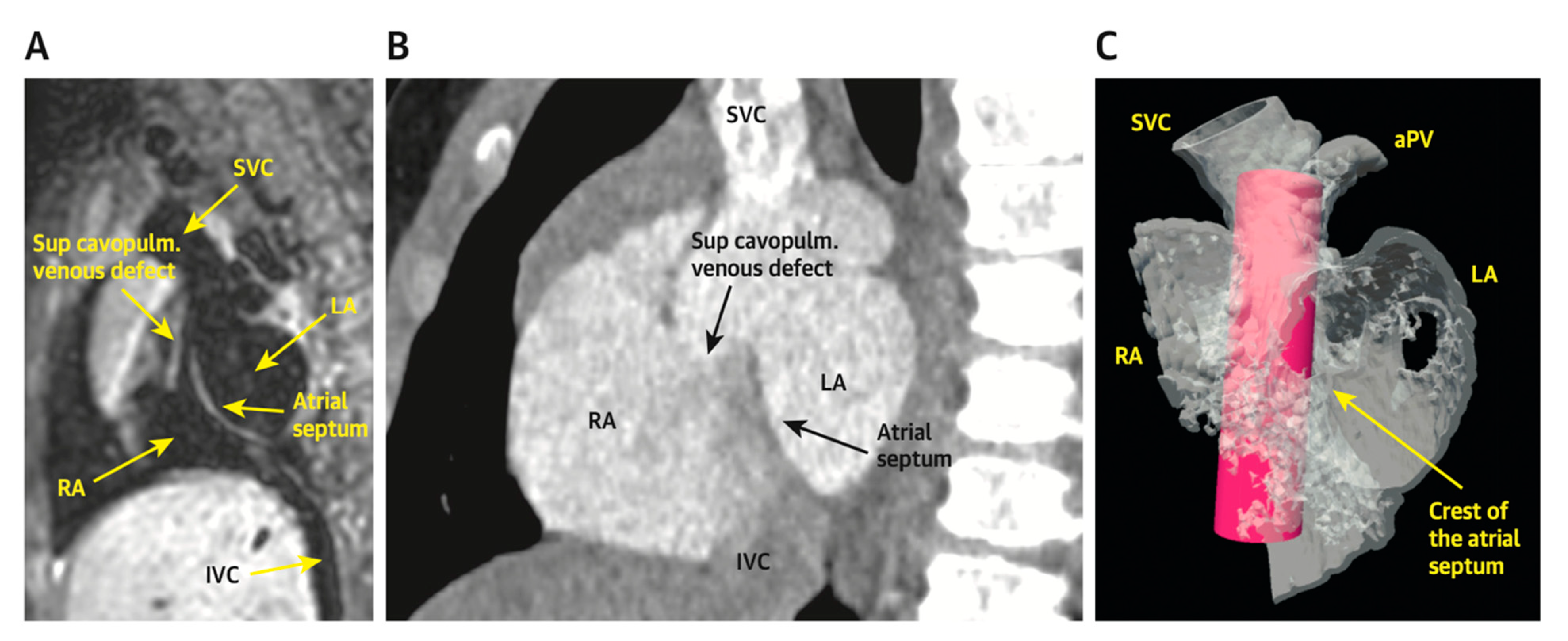
SVASD are characterized by an embryological defect between the wall of the superior vena cava (SVC) and right upper pulmonary vein (RUPV), leading to a significant left to right shunt
[1][2][3]. Cross-sectional imaging has played a vital role in the diagnosis and interventional planning for percutaneous closure. Not all patients are suitable candidates for transcatheter intervention as many factors must be considered pre-operatively including pulmonary vein insertion, length of SVC, and sites of possible obstruction from the covered stent placement.
The following
Figure 1,
Figure 2,
Figure 3,
Figure 4,
Figure 5 and
Figure 6 describe in detail the pre-procedural, intra-procedural, and post-procedural considerations
[4].
Figure 7 demonstrates how the “virtual reality” environment can provide a critical look at the cross-sectional imaging in an interactive platform to deliver a reliable understanding of the patient’s anatomical limitations
[5].
Figure 1. Illustration of successful covered stent placement with closure of the SVASD. The anomalous pulmonary veins now drain directly to the left atrium (LA) while the SVC drains entirely to the RA. Revised from ref
[4].
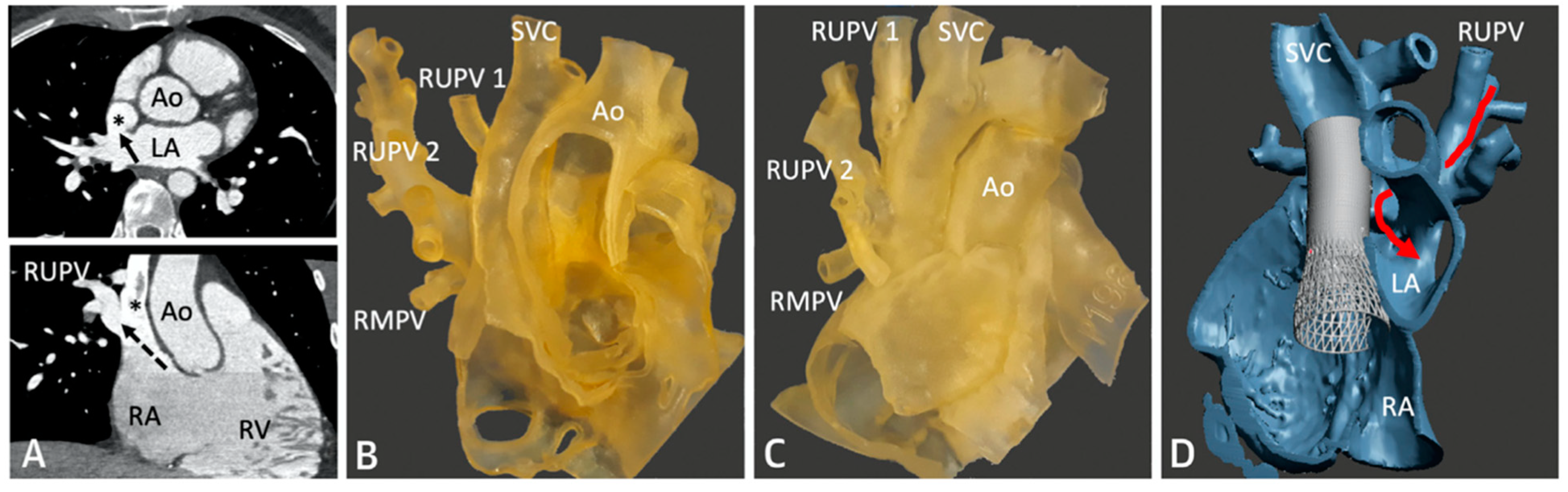
Figure 2. Series of images depicting pre-procedural planning with CT (
A), three-dimensional (3D) printed models (
B,
C), and 3D virtual modeling (
D). The defect is represented by an asterisk (*) in (
A). After review with 3D imaging, each patient was either referred for covered stent placement (
B,
D) or surgical repair (
C), if deemed inappropriate for percutaneous closure. Revised from ref
[4].
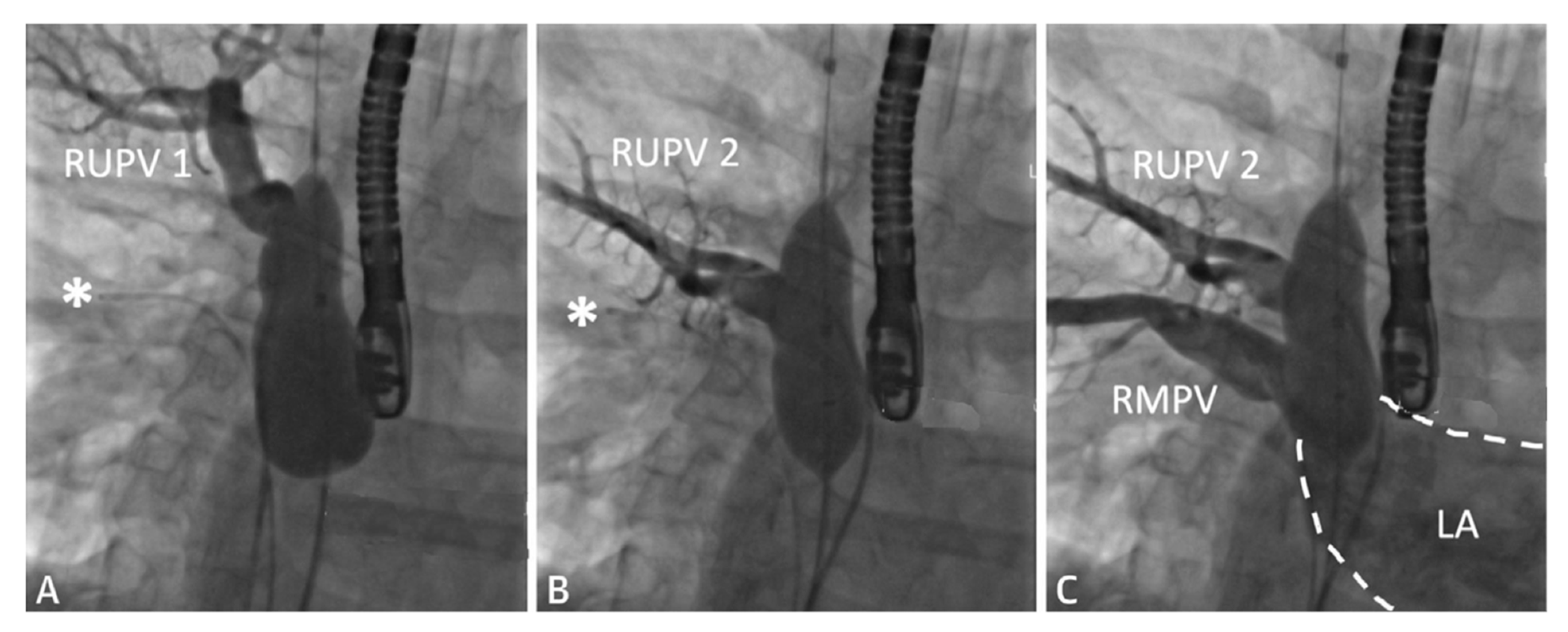
Figure 3. Series of fluoroscopy images depicting balloon test occlusion prior to covered stent placement. The patient was deemed to be an unsuitable candidate for covered stent placement as both RUPVs demonstrated an obstructive pattern returning to the LA (
A,
B). Venous return from the RMPV (
C) was normal. A catheter is seen at the asterisk (*). Revised from ref
[4].
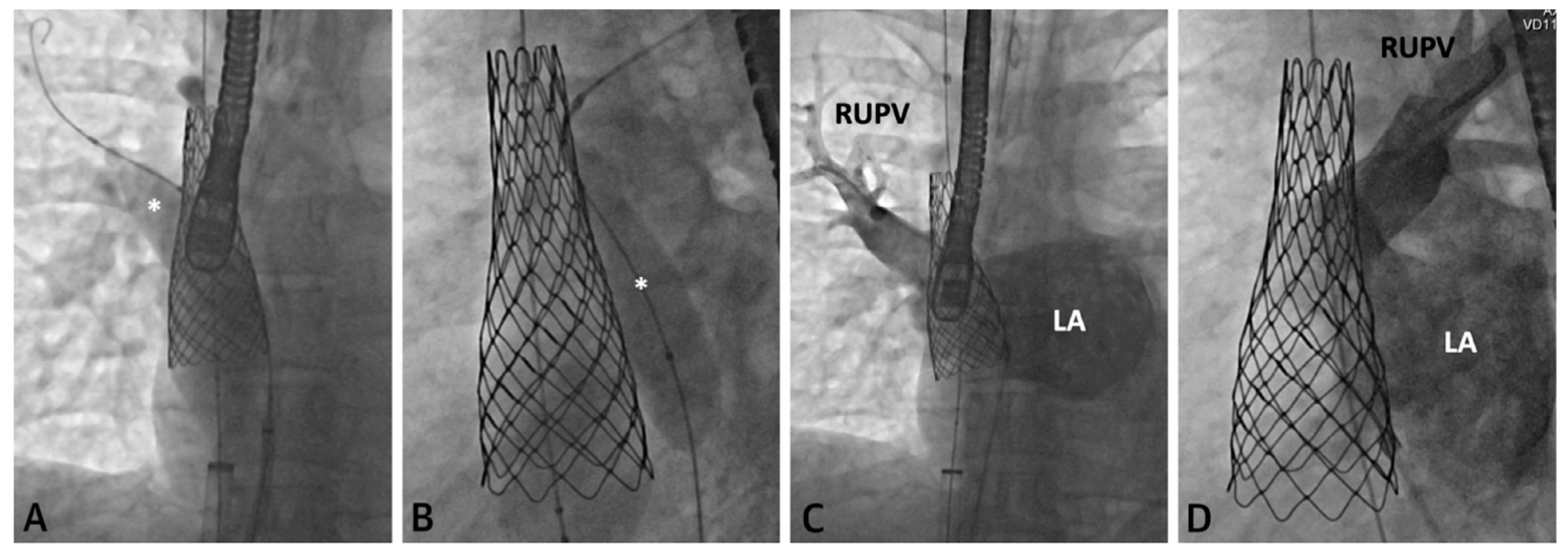
Figure 4. Series of fluoroscopy images depicting stent placement. An Atlas Gold Balloon (*) is placed in the RUPV to prevent obstruction during SVC covered stent deployment (
A,
B). Follow up hand injection angiogram in the RUPV demonstrates no residual narrowing and normal venous return (
C,
D). Revised from ref
[4].
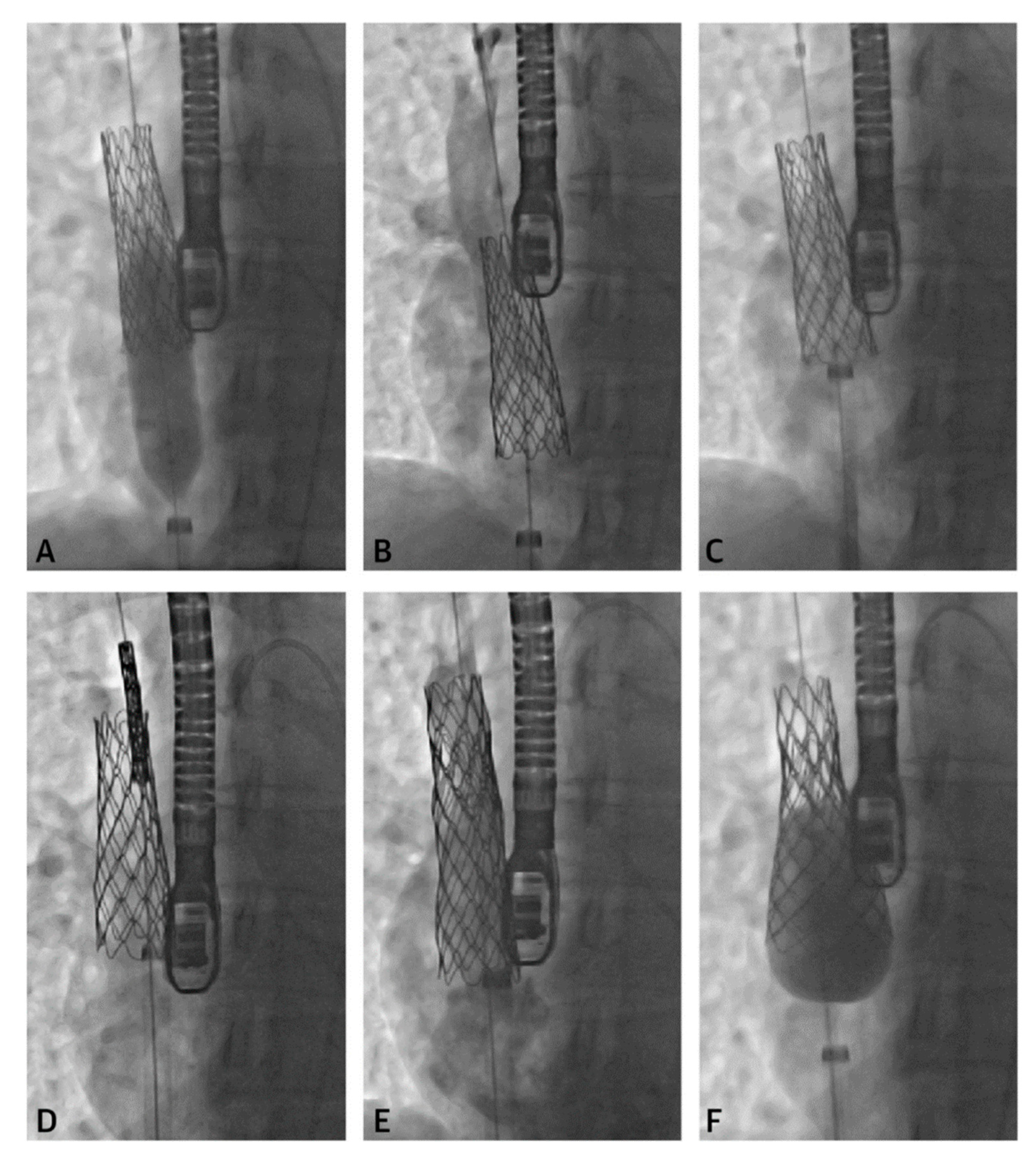
Figure 5. Series of fluoroscopy images depicting stent migration following attempted post-dilation (
A,
B). The stent was repositioned with the long sheath (
C) followed by another stent placement (
D,
E). A larger balloon was used to post-dilate the first stent into place (
F). Revised from ref
[4].
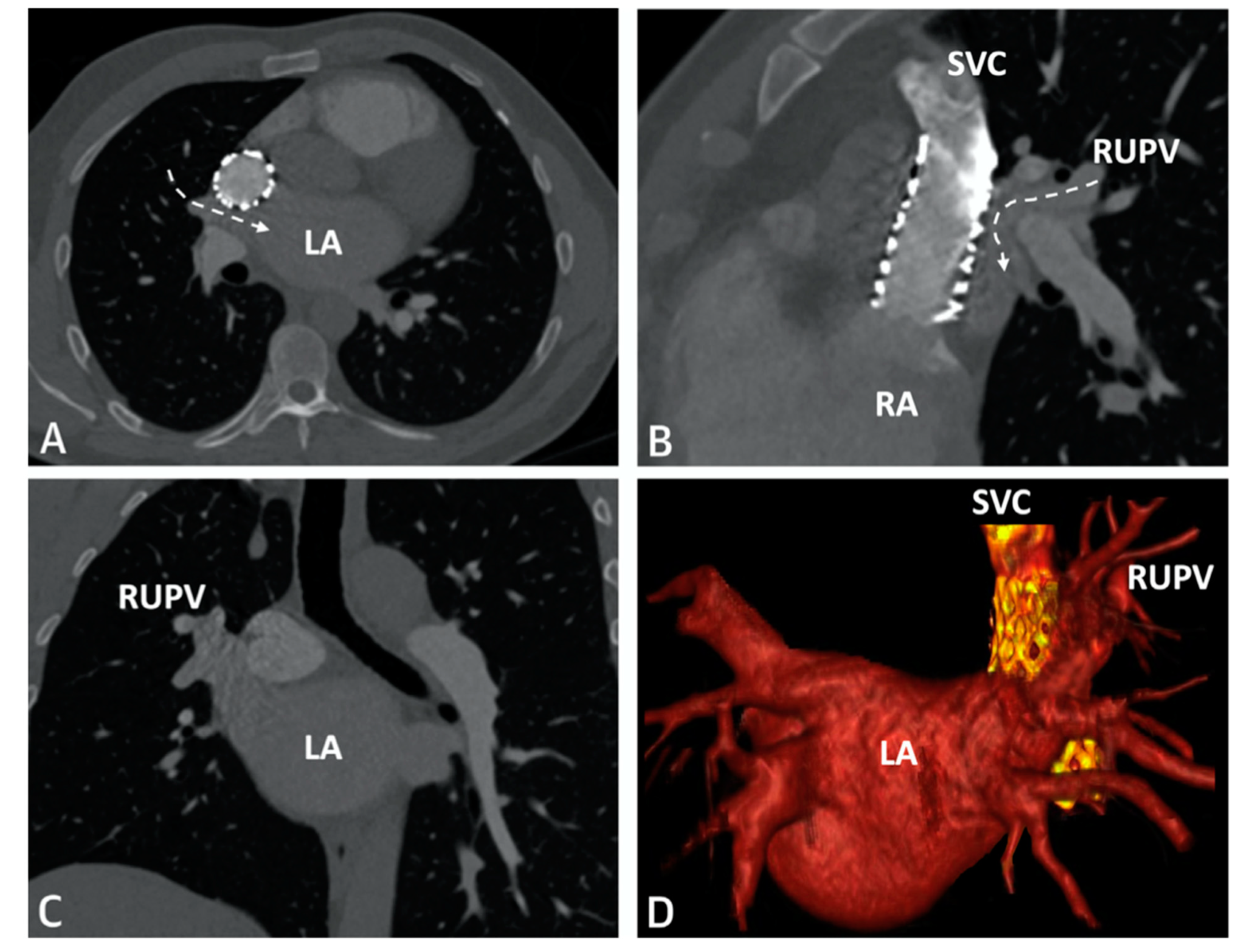
Figure 6. CT imaging following successful covered stent placement demonstrates no pulmonary venous obstruction to the LA (
A–
C). A 3D virtual model confirms unobstructed drainage from the pulmonary veins to the LA (
D). Revised from ref
[4].
Figure 7. Virtual reality simulation to better understand the relationship of the proposed covered stent to surrounding structures. Both patients in (
A) (CMR) and (
B) (CT) were deemed inappropriate candidates for covered stent placement due to SVC angulation to the LA. Imaging from the patient in (
B) was further confirmed using virtual reality (
C). The covered stent is represented by the pink cylinder. Revised from ref
[5].
2.2. Patent Ductus Arteriosus (PDA) Stenting for Ductal-Dependent Pulmonary Blood Flow
PDA stenting is emerging as an alternative to surgical shunts for PDA-dependent pulmonary blood flow in newborns with CHD. Every PDA is not created equal, and there are many considerations that must be evaluated before undertaking PDA stenting.
2.2.1. Pre-Procedural
Prior to catheterization, many centers routinely obtain cross-sectional imaging with contrast CT scan to better assess the take-off, tortuosity, and size of the PDA (
Figure 8 and
Figure 9)
[6][7][8].
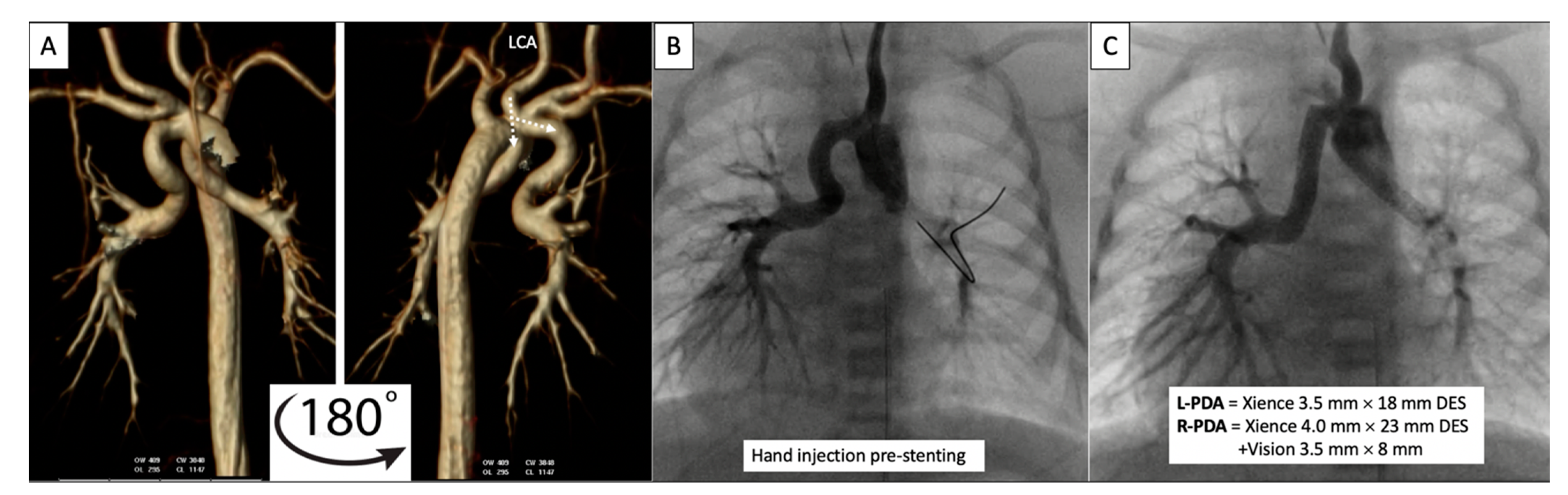
Figure 8. Pre-procedural 3D virtual CT imaging (
A) predicts the left carotid artery (LCA) as the best access site for bilateral PDA stenting (
B,
C) in a patient with discontinuous PAs. Multi-Link Vision and Xience Alpine
TM drug eluting (DES) stents (Abbott Vascular Company, Abbott Park, IL, USA) were used. Revised from ref
[9].
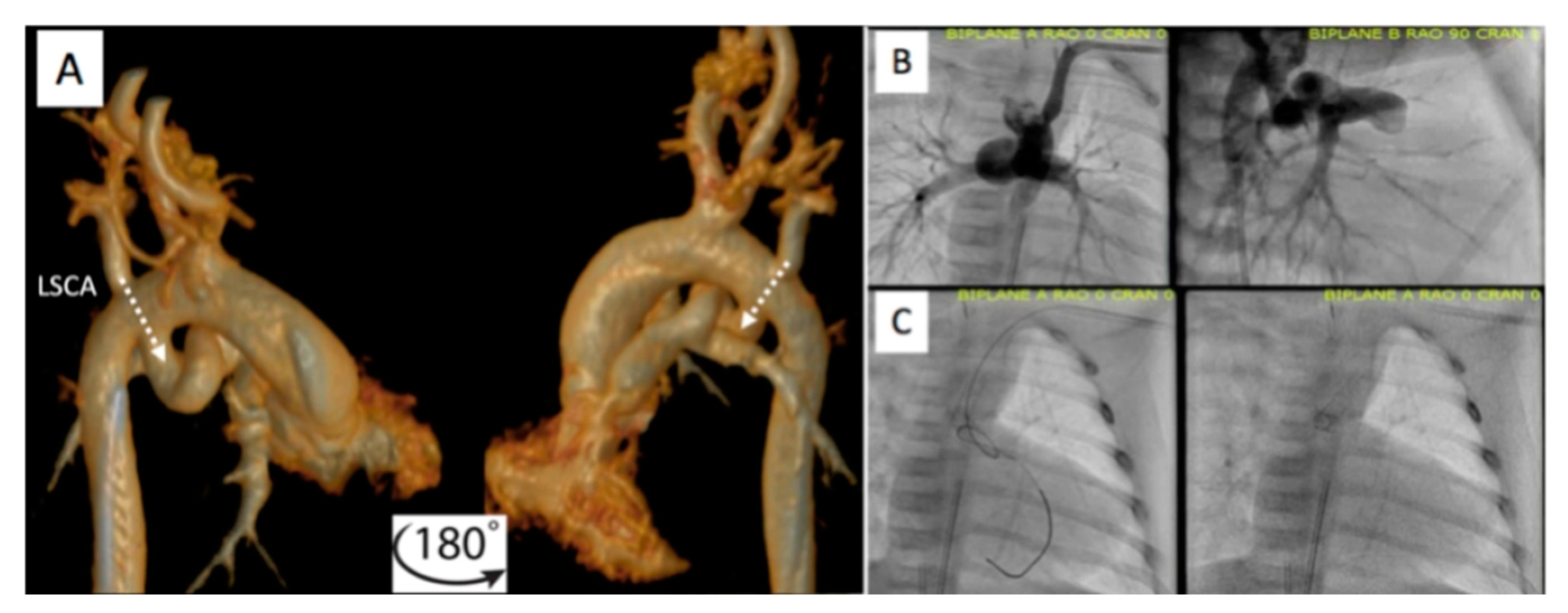
Figure 9. Additional example of pre-procedural CT imaging (
A) aiding with access site selection for successful PDA stenting (
B,
C) via the left axillary artery (LAA) to the left subclavian artery (LSCA). Revised from ref
[9].
2.2.2. Post-Procedural
Following the procedure, it is important to continue to monitor saturations to ensure the patient maintains adequate pulmonary blood flow. Figure 10 demonstrates an example of PDA stenting where the aortic end was not fully covered. The patient returned to the catheterization lab after this lesion was identified by CT scan and the stenotic aortic end was fully stented. The patient did well afterwards, saturations stabilized, and the patient was discharged home with close follow-up.
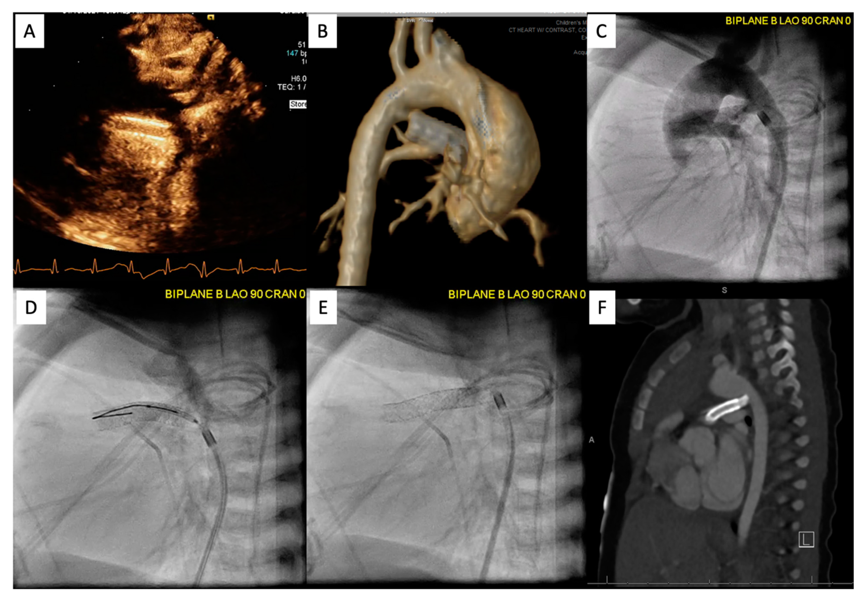
Figure 10. Patient is status post PDA stenting with concern for cyanosis. ECHO/CT scan demonstrated that the aortic end was uncovered (A,B). Patient returned to the catheterization lab for an additional stent placement (C–E). Follow up PDA stenting showed full coverage (F).
2.3. Percutaneous Pulmonary Valve Placement
Pre-Procedural
Cross-sectional imaging is an indispensable tool for patient counseling and planning prior to percutaneous pulmonary valve placement. The three leading Food and Drug Administration (FDA) approved percutaneous pulmonary valves utilized in the United States are (1) the Melody valve (Medtronic, Minneapolis, MN, USA), (2) the Sapien valve (Edwards Lifesciences, Irvine, CA, USA), and (3) the most recently approved Harmony valve (Medtronic, Minneapolis, MN, USA). Pre-procedural cross-sectional imaging allows for improved patient selection prior to catheterization.
2.4. Cross-Sectional Overlay Fusion in the Catheterization Lab
Cross-sectional overlay enabled registration of previously acquired CT and/or MRI images is being used to rapidly fuse with X-ray fluoroscopic imaging in single and biplane systems
[10][11]. Several single-plane overlay examples (VesselNavigator system (Philips Healthcare, Best, The Netherlands)) are outlined below (
Figure 18)
[12]. A biplane overlay example (Siemens bi-plane system (Siemens Healthineers, Munich, Germany) is depicted in
Figure 19 [13]. Overlay fusion has demonstrated a reduction in overall radiation burden
[8][9].
Figure 18. Symptomatic Fontan patient with severe lymphatic insufficiency presents following a dynamic contrast magnetic resonance lymphangiogram (
a) for fluoroscopic overlay guided retrograde lymphatic embolization (
b–
d) via the thoracic duct. Revised from ref
[9].
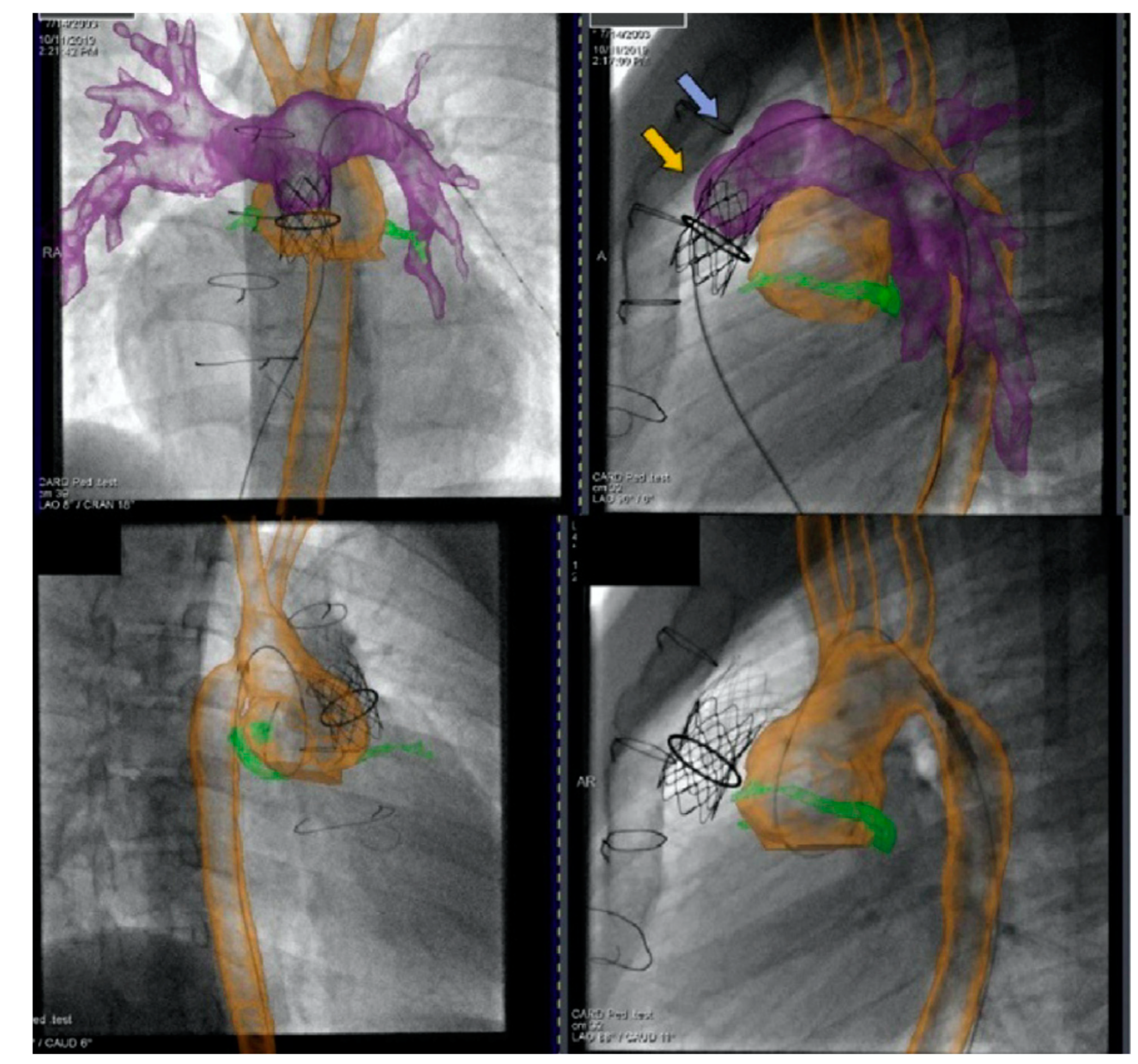
Figure 19. Biplane overlay (Siemens Healthineers, Munich, Germany) to assist with Melody valve placement (top row) followed by coarctation of the aorta (CoA) stenting in the same patient (bottom row). The pulmonary arteries are outlined in purple, and the aorta is outlined in orange. The two arrows point to the bare metal stent (yellow) within the valved conduit and newly placed Melody valve (violet). Ref
[13].
2.5. Coronary Artery Assessment in CHD
Congenital coronary interventions are rare, and the anatomy for each case is quite varied. Therefore, cross-sectional imaging can be extremely helpful when planning such interventions. An example of an anomalous left coronary artery from the pulmonary artery (ALCAPA) repair with residual left main coronary artery (LMCA) narrowing is outlined in
Figure 20 and
Figure 21. In addition, ongoing studies aim to assess pediatric coronary allograft vasculopathy with CT angiography and CMR adenosine stress perfusion
[14][15] to compliment traditional assessment by X-ray fluoroscopic catheter angiography.
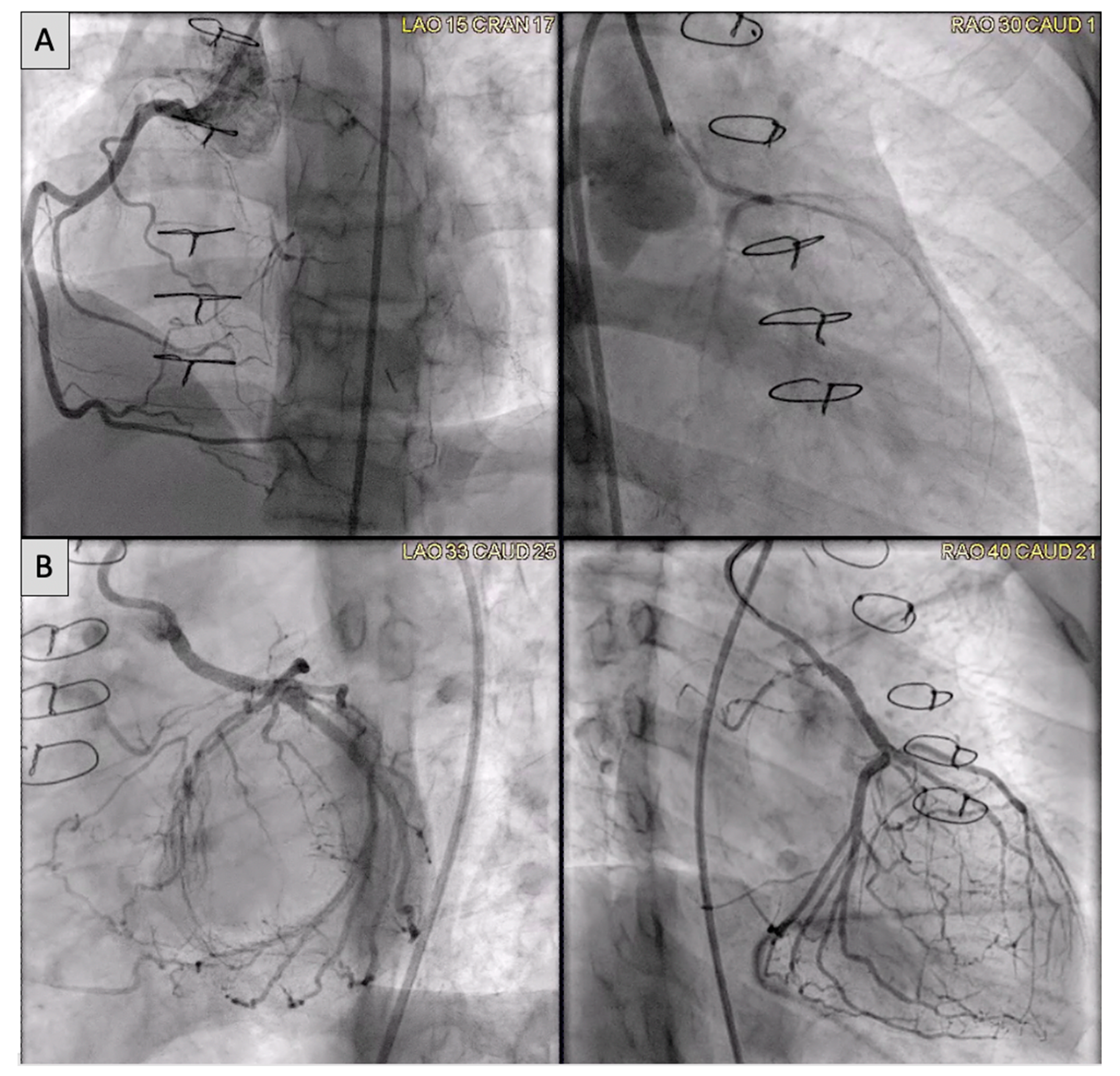
Figure 20. (A) Anomalous left coronary artery from the pulmonary artery (ALCAPA) patient status post reimplantation and now found to have severe proximal occlusion of the left main coronary artery (LMCA). (B) Post-stent placement in the LMCA with improved antegrade reperfusion on follow up angiography.
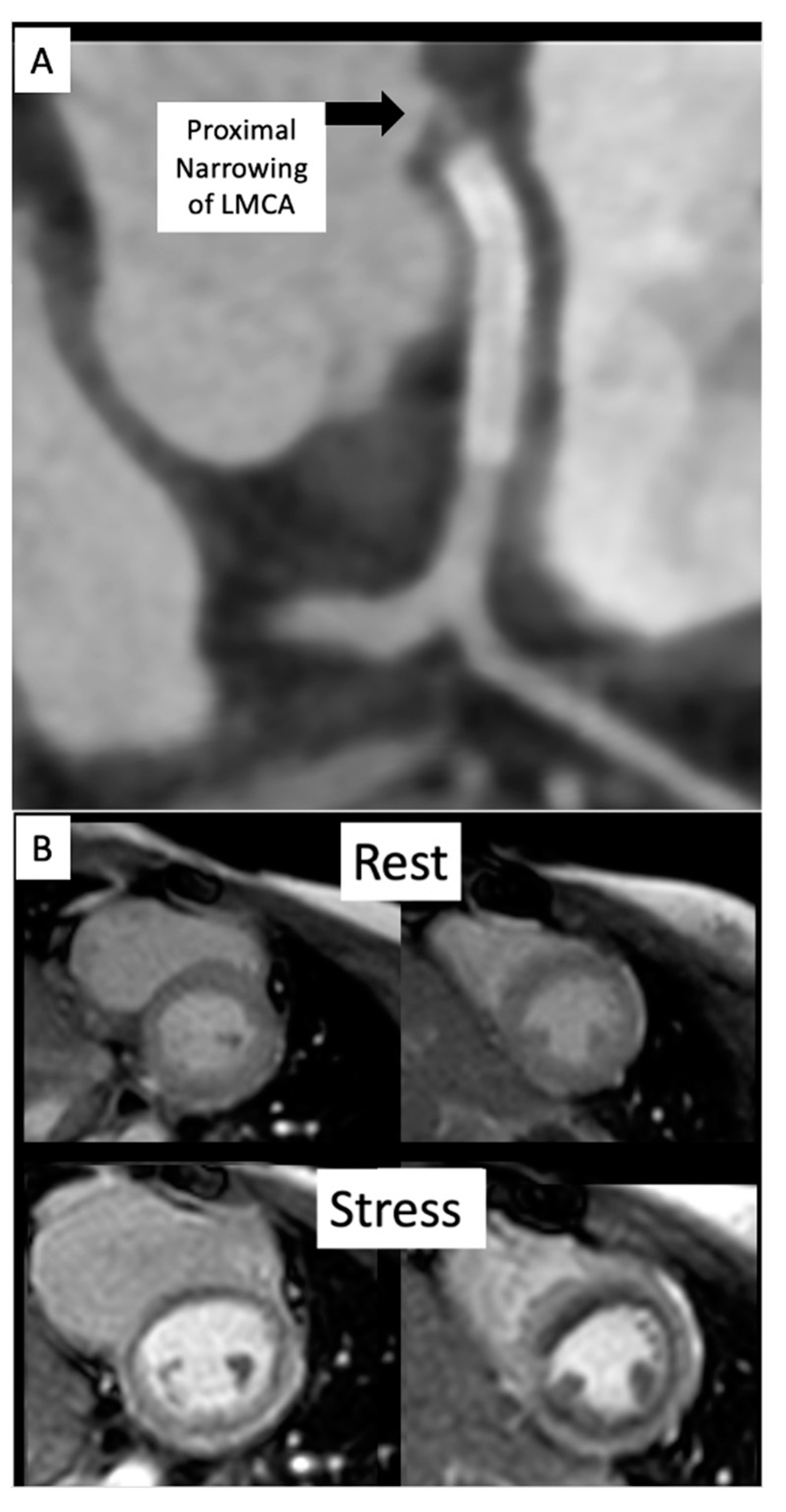
Figure 21. (A) CT on follow-up for patient from Figure 20 demonstrates a segment of near complete occlusion at the most proximal aspect of the left main coronary artery (LMCA), immediately prior to the previously placed stent. (B) Cardiac MRI demonstrated inducible perfusion defects along the anteroseptal, anterior, anterolateral, and lateral walls, at the basal and mid-ventricular level, as well as in the anterolateral papillary muscle (territory of the LMCA). No areas of late gadolinium enhancement to indicate myocardial fibrosis/injury are present. Patient proceeded to the catheterization lab for additional stenting of the LMCA ostium.
This entry is adapted from the peer-reviewed paper 10.3390/children9030300