However, the heating management becomes problematic for TD geometry when the same average power with a reduction of pulse energy requires a corresponding increasing repetition rate. These conditions involve the beam diameter reduction to keep output fluence around the saturation one (~1 J/cm
2) for the efficient energy extraction during an amplification. The volume reduction of the gain medium would lead to significant temperature growth, thus limiting the applications of this technology. The results of simulations presented in
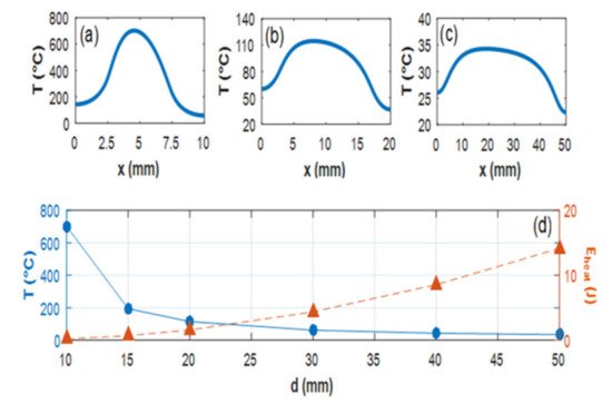
Figure 1 for a single-disk, active mirror configuration with back side cooling demonstrate these limitations
[16]. The flow coolant velocity of 2.4 m/s, pump energy varying from 0.4 to 10 J, and the disk size from 10 to 50 mm established to energy fluence of 2 J/cm
2 were used for this calculation. The reference pump average power was set to 350 W, while the repetition rate towards the lower pump energies was varied from 11 Hz to 900 Hz. The front surface temperature profiles at the center of crystal are shown in
Figure 1a–c. It can be clearly seen that the temperature profile steepens and becomes more asymmetric with the decrease in pump energy (decreasing the necessary Ti:Sa disk size) and the associated repetition rate increase needed to maintain the reference average power. The peak temperature reaches 700 °C, producing an extremely high thermal gradient between the center and the edges of the Ti:Sa disk, which cannot be tolerated in a real amplifier.
Thus, there is a trade-off between the crystal surface area required for heat extraction and keeping the output fluence near the saturation value.
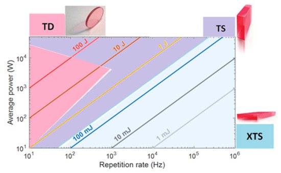
This problem was resolved by the changing TD geometry for a thin-slab (TS) configuration when pulse energy is within 0.1–10 J and repetition rate above 1 kHz. In TS, the different seed passes run through the neighbor area of the crystal, which allows enlarging of the heat extraction surface (see detailed explanation below).
Finally, for the energy below a few hundred mJ and repetition rate above 1 kHz, the further geometry change is required. In this case, the heat is extracted through the top and bottom largest surfaces of the slab, while the seed beam passes through the end faces for amplification (cross thin slab (XTS)). Approximate areas of the application of TD, TS, and XTS crystal geometries are presented in Figure 2.
More detailed discussion of these technologies is presented in the following text.
2.1. High Energy Amplifiers—TD Regime
The first time the TD technology was applied to Ti:Sa crystal and combined with the method of extraction during pumping (EDP-TD) was presented in
[15]. It was demonstrated that this combination overcomes both problems: the thermal effects in the amplifier heads due to the high repetition rate of laser systems, and the energy losses associated with TASE in thin crystals. The numerical simulations showed that the novel technology allows a high peak power Ti:Sa laser of a 100 TW-PW class to be scaled towards high average power, more than at a kW level. TD scaling was investigated by using the simulations with various parameters of the geometry, laser properties, and cooling. As an example, a model of the gain medium and coolant channel attached to it (direct cooling) was used. The coolant flow was simulated by using laminar and shear-stress transport (SST) turbulent models, from which one is chosen according to the flow conditions in the channel. The nonisothermal flow simulation is coupled to the heat transfer in the gain medium. Stationary analysis is always performed, giving relevant information regarding the thermal equilibrium of the laser head.
The experimental testing has presented a good agreement with these simulations. The results of a proof-of-principle experiment with an EDP-TD Ti:Sa amplifier are exhibited in
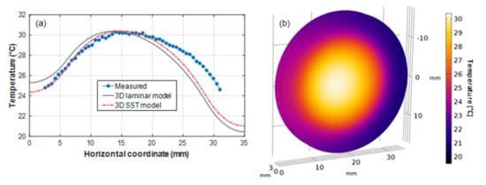
[8]. The obtained results demonstrated the capacity to build a room-temperature-cooled final amplifier, providing a few joules of energy of the seed laser pulses within a 100 s TW/10 s Hz CPA laser system. The EDP-TD amplifier was brought to saturation, reaching close to the theoretical maximum energy extraction efficiency of ~50% at only three amplification passes. These experimental conditions based on measured data were included in the simulations for numerical code validating. The simulations method was successfully confirmed by calculating the 3D temperature profile using both laminar and SST flow models and comparing with measured data (
Figure 3).
Figure 63. Comparison of measured and modeled temperature profiles in the central dissection line of the front surface of the Ti:Sa crystal (laminar flow model—grey line, SST turbulent model—red dashed line, the measured ones—blue dots (a). The 3D temperature distribution in the Ti:Sa crystal in the SST turbulent model (b).
There is good agreement between the measured and simulated data with the only observed difference in temperature profile near to the crystal edge (Figure 3a). This feature can be attributed to heating from absorbed TASE in the absorber fluid at the edge of the Ti:Sa disk.
Based on the validated numerical code, the developed simulations were performed for 1 kHz repetition rate operation of TD amplifiers in the multi-J energy regime
[17].
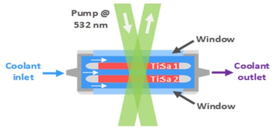
For kW average power, the twin thin disk configuration of amplifiers was used. Joule-level amplifiers operating at kHz repetition rate can generate the extremely high heat within a Ti:Sa medium. The water cooling of single crystal laser heads cannot support low temperature gradients in the kW average power pump regime. Figure 4 shows a double-crystal laser head which can still operate at room temperature. The thermal conditions during amplification at 1 kHz repetition rate were determined for a 2 J output amplifier with the simulation code restricted to 2D. The pump energy per pulse was set to 4 J, which was distributed in the double-crystal head.
Figure 4. Schema of a double-crystal amplifier head utilizing a transmission-based optical scheme for both pump and seed pulses.
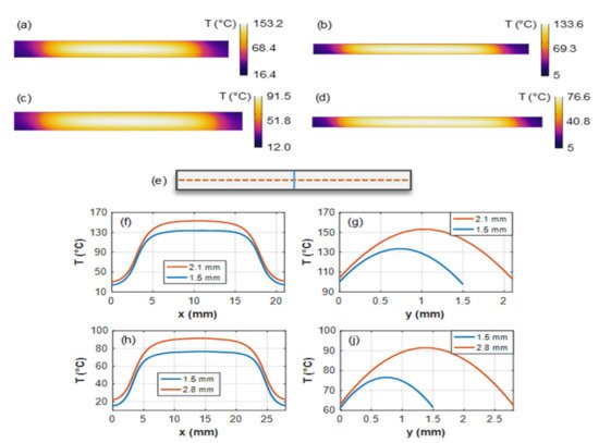
Figure 4 shows one head of the amplifier arrangement, where the scheme is greatly simplified. Contradirectional flows were taken for the simulations, which were previously shown to be effective in improving the temperature profile for TD amplifiers. The temperature distribution was calculated for 0.5 J/cm2 and 1 J/cm2 pump energy fluences per crystal (2 J pump energy per crystal), which represent a fluence of 1 J/cm2 and 2 J/cm2 in the case of the output seed pulses after amplifier, respectively, when assuming an amplification efficiency of 50%. Figure 5 shows the temperature maps and the profiles along the crystal cross sections. The water flow velocity was set to 4.5 m/s, which is obtainable with currently available high-pressure chillers and narrow coolant channels in the millimeter range.
Figure 5. Simulated temperature distribution in one Ti:Sa crystal from the twin-TD arrangement for 2.1 mm (a) and 1.5 mm (b) thicknesses with 21 mm diameter and 1 J/cm2 pump fluence per crystal, also for 2.8 mm (c) and 1.5 mm (d) thicknesses with 28 mm diameter and 0.5 J/cm2 pump fluence. Cross sections in the Ti:Sa crystal are represented by blue and orange curves in (f–i) parts of the figure (e). Temperature profiles in the cross sections of the Ti:Sa disk for 1 J/cm2 (f,g) and 0.5 J/cm2 (h,i) energy fluences for the two different disk thicknesses.
Figure 5 shows that the thermal management of the double-crystal head TD Ti:Sa technique can handle 2 J amplified pulses at 1 kHz repetition rate. Dividing the Ti:Sa disks into more pieces could further reduce the temperature.
2.2. Intermedium Energy Amplifiers—TS Regime
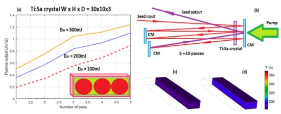
Thin-slab Ti:Sa crystal geometry allows to significantly enlarge the heat extraction surface, keeping the efficient energy extraction and seed pulse near the saturation fluence. The TS crystal shape is demonstrated in the insert of
Figure 6a, where the green region is the pump beam area and the red circles are seed passes. The possible optical schema of the amplifier is shown in
Figure 6b and uses a double-pass geometry with n sub-passes through the crystal to ensure efficient extraction. The imaging optics for relaying beams from pass to pass to keep a constant beam diameter should be included in the scheme of the amplifier. The two general passes of the seed have a good spatial overlapping with a small angle for separation of the input and output seed beams. Dependence of the output pulse energy on the number of double seed passes for different input pulse energy is represented by the curves in
Figure 6a. The pump energy of 1.8 J was taken for these calculations by using the Frantz–Nodvik solution for the photon transport equation
[18]. As seen from the curves, the amplifier can reach the joule level of energy of the seed pulse with a total gain of 3–8.
Figure 6. (a)—Thin-slab Ti:Sa crystal (insert); dependence of the output pulse energy on the number of double seed passes for different input pulse energy. (b)—Optical schema of the amplifier. (c,d)—3D simulation of temperature distribution in the crystal for different pumping conditions.
Temperature distribution in different pumping conditions was simulated in 3D, where the model consisted of the Ti:Sa slab only. The cooling of slab was introduced as a constant temperature boundary condition, an idealistic approximation to the real conditions, which is enough to estimate the limits of this configuration. The pump beam was taken to be flat-top and passed through the largest surface with the size which fit the slab’s aperture, leaving 0.1 mm on every side of the surface unpumped. The pump average power was tuned from 0.3 to 2 kW. The slab of 30 × 10 × 3 mm Ti:Sa crystal was tested for the pulsed 532 nm pump sources. The cooling temperature was set to 283 K for power levels up to 2 kW. The pump absorption in all cases was set to 95%, which can be reached by a few passes of the pump beams through the slab. The geometry even allows for room temperature coolant to keep the low temperature inside the Ti:Sa slab, which can be seen from Figure 6c,d. These calculations show that 1 kW output power at room temperature could be realized, which means, in case of 1 J energy per pulse, the 1 kHz repetition rates are possible.
2.3. Low Energy Amplifiers—XTS Regime
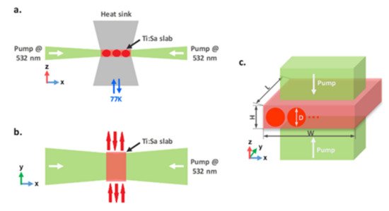
In the case of the low pulse energy, possible slab configurations are depicted in
Figure 7, where the heat is extracted through the top and bottom surfaces, while the seed beam passes through the end (side) faces for amplification. In contrast to the InnoSlab configuration
[16], several XTS schemes for the pump and seed can be used within this paradigm. The Ti:Sa slab can be either pumped through another two end faces (
Figure 7a,b)
[19], or through the cooled surfaces (
Figure 7c), where the pump beams are directed through one or both of the large surfaces of the crystal, as suggested in
[17]. Extraction efficiency can be kept high by using the multipass optical schemes similar to
Figure 6b, while different variants of the pumping are presented in
Figure 7a–c. Here, the seed beams are shown by red circles and arrows, and the pump by green ones.
Figure 7. Side (a) and top views (b) of side-pumped XTS geometry. Pumping from the cooled faces, where seed passes are also visualized on the slab (c).
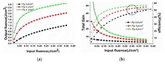
For pulsed pumping, the output seed fluence, the total gain and efficiency of energy extraction at different pump fluencies (Fp) were calculated for various input seed. The pump energy with a flat-top distribution absorbed in the slab was recalculated to Fp, matched with the seed beam diameter to be used in the Frantz–Nodvik equation. In the calculations, XTS amplifier with the crystal height, width, and length of 3 mm, 10 mm, and 30 mm, respectively, were taken, and the sub-pass number in one general pass through the whole slab is 3. Figure 8 shows that the gain decreases with an increase of input seed pulse while the efficiency is continuously increasing. Therefore, there is an optimum input seed fluence for both required gain and acceptable efficiency. Higher pump fluence provides both higher gain and higher efficiency with the same input seed fluence (Figure 8b), but heating of the slab also increases, bringing difficulties for heat removal with the same cooling area. For the XTS amplifier, the input fluence of 0.16 J/cm2 can be chosen while the pump fluence is 4 J/cm2, with energy extraction of efficiency of 52% and the output fluence around 2 J/cm2 (gain of ~14).
Figure 8. Evolution of the output seed fluence (a); gain and energy extraction efficiency (b) on the input seed fluence at different pump fluence values.
If the input seed fluence is increased to 0.3 J/cm2, saturation will be further enhanced (energy extraction efficiency of ~56%) but the gain drops to around 8.5. The seed can be amplified from 11 mJ to 160 mJ when pump energy of ~280 mJ is applied.
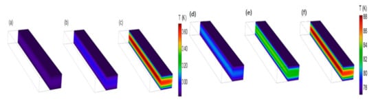
Temperature distribution in the different pumping conditions was also simulated in 3D. The pump beam passes through the top and bottom of the crystal. The slab of size 30 × 10 × 3 mm was tested for the pulsed 532 nm pump with average power from 0.3 to 30 kW. The cooling temperature was 283.15 K for power levels up to 5 kW (Figure 9a–c) and was reduced to 77 K for higher pump power (Figure 9d–f).
Figure 9. Temperature distribution of the top–bottom-pumped Ti:Sa slab for 300 W (a), 1 kW (b), and 5 kW (c) pump powers and 283 K cooling temperature, and for 10 kW (d), 20 kW (e), and 30 kW (f) powers and 77 K cooling temperature. For better visibility, only half of the slab is visualized. The pump wavelength was set to 532 nm, and crystal size of 30 × 10 × 3 mm.
One can conclude from these simulations that an operation at room temperature could be realized up to 2–3 kW pumping, but for sub-5 kW seems to be less effective, which implies the need of cryogenic cooling. For this purpose, amplifications with cooling at 77 K were investigated with up to 30 kW pump power, and the results of heating simulations are demonstrated in
Figure 9d–f. The thermal lens along the vertical direction was estimated by using the formula of f
h = K·W·H/(χ·P
h)
[19], where K is the thermal conductivity and χ is the thermo-optic coefficient (dn/dT ~0.97 × 10
−5 1/K
[20]); thermal induced deformation and stress are neglected. Temperature dependence on vertical position was obtained from numerical modeling and calculating the average volume of temperature in the slab. The focal lengths 7.6, 3.4, and 2 m of the thermal lens created in the crystal were found for 10, 20, and 30 kW pumping power, respectively.
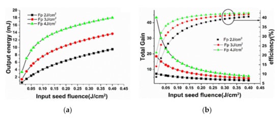
Continuous wave pumping of Ti:Sa crystals by an existing laser diode of the blue-green diapason is also a very attractive task for a possible application. Current laser diodes existing at this wavelength range operate in a CW regime, so a much higher repetition rate is required for an efficient pumping due to the necessity of time delay between two consequent pulses shorter than the lifetime of the upper Ti:Sa crystal laser level (3.2 μs). At the same time, the required repetition rate of 1–2 MHz would result in significant overheating of the crystal. Using XTS configuration enables the repetition rate and the average power to be increased significantly whilst maintaining a reasonable crystal temperature
[18]. The system with CW blue laser diode pumped XTS amplifier was used for calculation. The repetition rate of the pulsed seed was assumed to be 1 MHz to achieve higher energy extraction efficiency. The slab amplifier (1 mm × 10 mm × 10 mm) was analyzed, and the seed pulse energy, the gain, and energy extraction efficiency were calculated and are shown in
Figure 10. The efficiency increases with the input seed fluence is similar to the pulsed pump case, excluding the maximum achievable efficiency, which is lower because of the decay of stored pump energy between two consecutive pulses. Meanwhile, the energy extraction efficiency of CW pumping at relatively low input seed fluence (e.g., 0.05–0.1 J/cm
2) is higher than that of pulsed pumping mode, because undepleted pump energy will be partially preserved for the following shots (the upper lifetime is larger than the period between two pulses)—this is beneficial for controlling the average pump power.
Figure 10. Evolution of the output seed energy (a); total gain and energy extraction efficiency (b) on the input seed fluence for different pump fluence values.
It is possible to achieve 30–40% energy extraction efficiency, which is much higher compared to previous work
[21]. The input seed fluence of 0.1 J/cm
2 was chosen for three different pump fluences of 2, 3, and 4 J/cm
2 (calculated as for pulsed case). The seed energy was amplified from 0.8 mJ to 4, 8, and 12 mJ, respectively (gain of ~5, 10, and 16), with the pump power from 10 to 30 kW.
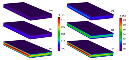
Thermal modeling with CW pumping was performed for pump wavelength set to 450 nm. Room temperature operation with 10 × 10 × 1 mm geometry was initially tested for 0.3, 1, and 5 kW pumping (Figure 11a–c) with a coolant temperature of 283.15 K. Top–bottom pumping was assumed, resulting in a lower absorption rate of 83.5% due to the smaller thickness of the slab. The temperature along the large surface is quite constant, while the temperature profile along the height dimension was parabolic with cylindrical thermal lens of 600 mm, 160 mm, and 25 mm respectively.
Figure 11. Temperature distribution of the top–bottom-pumped Ti:Sa slab for 300 W (a), 1 kW (b), and 5 kW (c) pump powers and 283 K cooling temperature, and for 10 kW (d), 20 kW (e), and 30 kW (f) powers and 77 K cooling temperature. For better visibility, only half of the slab is visualized. The pump wavelength is 450 nm, and crystal size of 10 × 10 × 1 mm.
Cryogenic cooling was tested with the same pumping configuration, and the quantum efficiency increases for the corresponding temperature change from 283 K to 77 K, which reduces the heat dissipation factor. Figure 11d–f shows that cooling at 77 K temperature is efficient, even for 30 kW pump power. The temperature peaks vary from 80 K to 91 K. The focal length of the thermal lens in the y-direction was estimated here also. The temperature dependence of the thermal conductivity and the thermo-optic coefficient was included in this model, where 0.73, 0.33, and 0.19 m focal lengths were calculated for the 10, 20, and 30 kW pumping, respectively. The extremely large thermal conductivity and small thermo-optic coefficient at this temperature means the thermal lens can be compensated for these amplifiers, making the cryogenic cooling CW diode-pumped Ti:Sa XTS amplifier a promising route for efficient high to average power systems.